Demonstration of different mechanisms in Hydraulic Assisted Power Steering (Ball Circulation).
•Download as DOCX, PDF•
0 likes•87 views

Demonstration of different mechanisms in Hydraulic Assisted Power Steering (Ball Circulation).

Recommended
More Related Content
What's hot
Similar to Demonstration of different mechanisms in Hydraulic Assisted Power Steering (Ball Circulation).
Similar to Demonstration of different mechanisms in Hydraulic Assisted Power Steering (Ball Circulation). (20)
More from Salman Jailani
More from Salman Jailani (20)
Recently uploaded
Recently uploaded (20)
Demonstration of different mechanisms in Hydraulic Assisted Power Steering (Ball Circulation).
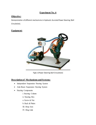
- 1. Experiment No. 6 Objective: Demonstration of different mechanisms in Hydraulic Assisted Power Steering (Ball Circulation). Equipment: Fig6.1 (Power Steering Ball Circulation) Descriptionof Mechanisms and Systems: Independent Suspension Steering System Axle-Beam Suspension Steering System Steering Components i. Steering Column ii. Steering Box a. Screw & Nut b. Rack & Pinion III. Drop Arm IV. Drag Link
- 2. V. Track Rod VI. Track Rod Arm VII. Axle Beam Hydraulic Assisted Power Steering Mechanism i. Pump ii. Control Valve iii. Ram Cylinder Procedure: As the bar twists, it rotates the inside of the spool valve relative to the outside. Since the inner part of the spool valve is also connected to the steering shaft (and therefore to the steering wheel), the amount of rotation between the inner and outer parts of the spool valve depends on how much torque the driver applies to the steering wheel. When the steering wheel is not being turned, both hydraulic lines provide the same amount of pressure to the steering gear. But if the spool valve is turned one way or the other, ports open up to provide high-pressure fluid to the appropriate line and assist the steering.