Inversion of mechanism
•Download as PPTX, PDF•
0 likes•717 views

Inversion of Mechanism Inversion of Four bar Mechanism Inversion of Single slider crank chain mechanism Inversions Of Double Slider Crank Chain

Recommended
More Related Content
What's hot
What's hot (20)
Similar to Inversion of mechanism
Similar to Inversion of mechanism (20)
More from R A Shah
More from R A Shah (19)
Recently uploaded
Recently uploaded (20)
Inversion of mechanism
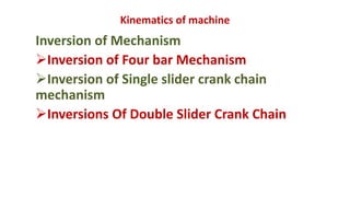
- 1. Kinematics of machine Inversion of Mechanism Inversion of Four bar Mechanism Inversion of Single slider crank chain mechanism Inversions Of Double Slider Crank Chain
- 2. What is INVERSION OF MECHANISM ? “ Method of obtaining different mechanisms by fixing different links one by one in turn in a kinematic chain, is known as inversion of the mechanism. ” We have already discussed that when one of links is fixed in a kinematic chain, it is called a mechanism. So we can obtain as many mechanisms as the number of links in a kinematic chain by fixing, in turn, different links in a kinematic chain.
- 3. Inversions: By fixing each link at a time we get as many mechanisms as the number of links, then each mechanism is called ‘Inversion’ of the original Kinematic Chain. Question: List out and explain Inversions of four bar chain mechanism: There are three inversions: 1) Beam Engine or Crank and lever mechanism. 2) Coupling rod of locomotive or double crank mechanism. 3) Watt’s straight line mechanism or double lever mechanism
- 4. 1. Beam Engine: When the crank AB rotates about A, the link CE pivoted at D makes vertical reciprocating motion at end E. This is used to convert rotary motion to reciprocating motion and vice versa. It is also known as Crank and lever mechanism. Application: This configuration, with the engine directly driving a pump
- 5. This mechanism is shown in the figure below.
- 6. B D A C E
- 7. 2. Coupling rod of locomotive: In this mechanism the length of link AD = length of link BC. Also length of link AB = length of link CD. When AB rotates about A, the crank DC rotates about D. Link AD is fix. Application: this mechanism is used for coupling locomotive wheels. Since links AB and CD work as cranks, this mechanism is also known as double crank mechanism.
- 8. A B C D1 2 3 4 This is shown in the figure below.
- 9. 3. Watt’s straight line mechanism or Double lever mechanism: In this mechanism, the links AB & DE act as levers. At the ends A and E of these levers are fixed. The AB & DE are parallel in the mean position of the mechanism and coupling rod BD is perpendicular to the levers AB & DE. On any small displacement of the mechanism the tracing point ‘C’ traces the shape of number ‘8’, a portion of which will be approximately straight. Hence this is also an example for the approximate straight line mechanism. Application: straight line mechanism development by Watt for guiding the piston of steam engines. This mechanism is shown below.
- 11. Question: List out and explain Inversions of Single Slider crank Chain: It is a chain having one sliding pair and three turning pairs. It is shown in the figure below. The purpose of this mechanism is to convert rotary motion to reciprocating motion and vice versa. 1 1 2 3 4
- 14. Question: List out and explain Inversions of a single Slider crank chain Mechanism: There are four inversions in a single slider chain mechanism. They are: 1) Reciprocating engine (I.C. Engine) mechanism (1st inversion) 2) Oscillating cylinder engine mechanism (2nd inversion) 3) Crank and slotted lever mechanism (2nd inversion) 4) Whitworth quick return motion mechanism (3rd inversion) 5) Rotary engine mechanism (3rd inversion) 6) Bull engine mechanism (4th inversion) 7) Hand Pump (4th inversion)
- 15. 1. Reciprocating engine mechanism : In the first inversion, the link 1 i.e., the cylinder and the frame is kept fixed. The fig below shows a reciprocating engine. A slotted link 1 is fixed. When the crank 2 rotates about O, Connecting rod 3 oscillates. the sliding piston 4 reciprocates in the slotted link 1. Application: This mechanism is used in steam engine, pumps, compressors, I.C. engines, etc.
- 17. 2. Oscillating cylinder engine Another Inversion of the single slider crank chain mechanism can be obtained by fixing the turning pair.
- 18. As you can see the schematic representation of the oscillating cylinder which is one of the inversions for the single sliding crank mechanism. In this oscillating cylinder engine, the connecting rod which makes the turning pair is fixed, instead of this connecting rod oscillation, the cylinder will oscillate when the crank rotates and is connected by the piston rod.
- 19. 3. Crank and slotted lever quick return motion mechanism:
- 20. In this type of Inversion of Single Slider Crank Mechanism also one turning pair is fixed as shown in the fig.
- 21. As you can see the above schematic representation of the crank and slotted lever mechanism, there will be a slotted bar which is fixed at one and at A. And also connected to the crank by the slider at B. As you can see the other end(P) of the slotted bar is connected to the ram of the machine where the tool post holds the tool. As the crank rotates, the slotted bar starts oscillates forward and backward. The name quick returns represent that when the slotted bar moves backward direction, it will be quicker than the forward movement. As it should travel the angle α while backward movement instead of the forward movement β. In the quick return mechanisms This mechanism transmits the rotary motion to the linear motion.
- 22. Application: This mechanism is used in shaping machines, slotting machines and in rotary engines.
- 23. 4. Whitworth quick return motion mechanism: The Whitworth quick return mechanism converts rotary motion into reciprocating motion, but unlike the crank and slider, the forward reciprocating motion is at a different rate than the backward stroke. ... This mechanism is most commonly seen as the drive for a shaping machine.
- 25. In this mechanism also there will be a slotted bar that is fixed at point D and connected to the crank by a slider and at the other end connected to the connecting rod connected to the ram of the tool post. Here also the backward movement is quicker than the forward movement. This mechanism also transmits the rotary motion to the linear motion. These are the Inversions of Single Slider Crank Chain Mechanism.
- 26. Application: The quick return motion mechanism is used in shapers and slotting machines.
- 27. 5. Rotary internal combustion engine A rotary engine consists of the 7 cylinders in one plane and all revolves about the fixed centre as you can see in the below schematic representation.
- 28. Rotary engine mechanism or Gnome Engine: Rotary engine mechanism or gnome engine is another application of third inversion. It is a rotary cylinder V – type internal combustion engine used as an aero – engine. But now Gnome engine has been replaced by Gas turbines. The Gnome engine has generally seven cylinders in one plane. The crank OA is fixed and all the connecting rods from the pistons are connected to A. In this mechanism when the pistons reciprocate in the cylinders, the whole assembly of cylinders, pistons and connecting rods rotate about the axis O, where the entire mechanical power developed, is obtained in the form of rotation of the crank shaft.
- 29. This mechanism is shown in the figure below.
- 30. Why gnome engine has odd cylinder? Rotaries have odd numbers of cylinders so that the ignition can be timed to fire every other cylinder, with a firing order of cylinder 1, then 3-5-7- 9-2-4-6-8. The alternating firing order results in smooth running. Most radial engines have an odd number of cylinders for the same reason.
- 31. 6. Pendulum pump or Bull engine Mechanism. In this mechanism, the inversion is obtained by fixing the cylinder or link 4 (i.e. sliding pair). In this case, when the crank (link 2) rotates, the connecting rod (link 3) oscillates about a pin pivoted to the fixed link 4 at A and the piston attached to the piston rod (link 1) reciprocates. The duplex pump which is used to supply feed water to boilers have two pistons attached to link 1.
- 32. This mechanism is shown in the figure below.
- 33. Kinematics of machine Inversion of Double slider crank chain mechanism
- 34. Question: List out and explain INVERSIONS OF DOUBLE SLIDER CRANK CHAIN Double Slider Crank Chain: A four bar chain having two turning and two sliding pairs such that two pairs of the same kind are adjacent is known as double slider crank chain. Inversions of Double slider Crank chain: It consists of two sliding pairs and two turning pairs. They are three important inversions of double slider crank chain. 1) Elliptical trammel. 2) Scotch yoke mechanism. 3) Oldham’s Coupling.
- 35. 1. Elliptical Trammel: This is an instrument for drawing ellipses. Here the slotted link is fixed. The sliding block P and Q in vertical and horizontal slots respectively. The end R generates an ellipse with the displacement of sliders P and Q. The co-ordinates of the point R are x and y. From the fig. cos θ = x. PR and Sin θ = y. QR
- 36. It is an instrument used for drawing ellipses. This inversion is obtained by fixing the slotted plate (link 4),The fixed plate or link 4 has two straight grooves cut in it, at right angles to each other. The link 1 and link 3, are known as sliders and form sliding pairs with link 4. The link (link 2) is a bar which forms turning pair with links 1 and 3. When the links 1 and 3 slide along their respective grooves, any point on the link 2 such as P traces out an ellipse on the surface of link 4, A little consideration will show that AP and BP are the semi-major axis and semi-minor axis of the ellipse respectively
- 38. 2. Scotch yoke mechanism: This mechanism is used for converting rotary motion into a reciprocating motion. The inversion is obtained by fixing either the link 1 or link 3. In Fig., link 1 is fixed. In this mechanism, when the link 2 (which corresponds to crank) rotates about B as centre, the link 4 (which corresponds to a frame) reciprocates. The fixed link 1 guides the frame.
- 41. 3. Oldham’s coupling: The third inversion of obtained by fixing the link connecting the 2 blocks P & Q. If one block is turning through an angle, the frame and the other block will also turn through the same angle. It is shown in the figure below.
- 42. It is shown in the figure below.
- 44. An application of the third inversion of the double slider crank mechanism is Oldham’s coupling shown in the figure. This coupling is used for connecting two parallel shafts when the distance between the shafts is small. The two shafts to be connected have flanges at their ends, secured by forging. Slots are cut in the flanges.
- 45. Machine: It is a combination of resistant bodies with successfully constrained motion which is used to transmit or transform motion to do some useful work. E.g.: Lathe, Shaper, Steam Engine, etc.