SlideShare a Scribd company logo
1 of 31
Experiment No.2
Objective:
Study of Chemical machining and process of chemical machining
Theory:
Chemicalmachining:
Chemical milling or industrial etching is the subtractive manufacturing process of using baths of
temperature-regulated etching chemicals to remove material to create an object with the desired
shape. It is mostly used on metals, though other materials are increasingly important. It was
developed from armor-decorating and printing etching processes developed during the
Renaissance as alternatives to engraving on metal. The process essentially involves bathing the
cutting areas in a corrosive chemical known as an etchant, which reacts with the material in the
area to be cut and causes the solid material to be dissolved; inert substances known as maskants
are used to protect specific areas of the material as resists.
Figure 1 (Chemical machining)
Application:
Etching has applications in the printed circuit board and semiconductor fabrication industries. It
is also used in the aerospace industry to remove shallow layers of material from large aircraft
components, missile skin panels, and extruded parts for airframes. Etching is used widely to
manufacture integrated circuits and Micro electro mechanical systems. In addition to the
standard, liquid-based techniques, the semiconductor industry commonly uses plasma etching.
Process:
Chemical milling is normally performed in a series of five steps: cleaning, masking, scribing,
etching, and demarking.
Cleaning:
Cleaning is the preparatory process of ensuring that the surface to be etched is free of
contaminants which could negatively impact the quality of the finished part. An improperly
cleaned surface could result in poor adhesion of the masking, causing areas to be etched
erroneously, or a non-uniform etch rate which could result in inaccurate final dimensions. The
surface must be kept free from oils, grease, primer coatings, markings and other residue from the
marking out process, scale (oxidation), and any other foreign contaminants. For most metals, this
step can be performed by applying a solvent substance to the surface to be etched, washing away
foreign contaminants. The material may also be immersed in alkaline oils from human skin could
easily contaminate the surface.
Masking:
Masking is the process of applying the masking material to the surface to ensure that only
desired areas are etched. Liquid mask ants may be applied via dip-masking, in which the part is
dipped into an open tank of masking and then the mask ant dried. Masking may also be applied
by flow coating: liquid masking is flowed over the surface of the part. Certain conductive mask
ants may also be applied by electrostatic deposition, where electrical charges are applied to
particles of masking as it is sprayed onto the surface of the material. The charge causes the
particles of masking to adhere to the surface.
Masking types:
The masking to be used is determined primarily by the chemical used to etch the material, and
the material itself. The masking must adhere to the surface of the material, and it must also be
chemically inert enough with regards to the etchant to protect the work piece. Most modern
chemical milling processes use maskants with an adhesion around 350 g cm−1; if the adhesion is
too strong, the scribing process may be too difficult to perform. If the adhesion is too low, the
etching area may be imprecisely defined. Most industrial chemical milling facilities usemaskants
based upon neoprene elastomers or isobutylene-isoprene copolymers. Maskants to be used in
photochemical machining processes must also possess the necessary light-reactive properties.
Scribing:
Scribing is the removal of masking on the areas to be etched. For decorative applications, this is
often done by hand through the use of a scribing knife, etching needle or similar tool; modern
industrial applications may involve an operator scribing with the aid of a template or use
computer numerical control to automate the process. For parts involving multiple stages of
etching, complex templates using color codes and similar devices may be used.
Etching:
Etching is the actual immersion of the part into the chemical bath, and the action of the chemical
on the part to be milled. The time spent immersed in the chemical bath determines the depth of
the resulting etch; this time is calculated via the formula:
Where E is the rate of etching (usually abbreviated to etch rate), s is the depth of the cut required,
and t is the total immersion time. Etch rate varies based on a number of factors, including the
concentration and composition of the etchant, the material to be etched, and temperature
conditions. Due to its inconstant nature, etch rate is often determined experimentally
immediately prior to the etching process. A small sample of the material to be cut, of the same
material specification, heat-treatment condition, and approximately the same thickness is etched
for a certain time; after this time, the depth of the etch is measured and used with the time to
calculate the etch rate. Aluminum is commonly etched at rates around 0.178 cm/h, and
magnesium about 0.46 cm/h.
Demarking:
Demarking is the combined process of clearing the part of etchant and masking. Etchant is
generally removed with a wash of clear, cold water (although other substances may be used in
specialized processes). A de-oxidizing bath may also be required in the common case that the
etching process left a film of oxide on the surface of the material. Various methods may be used
to remove the masking, the most common being simple hand removal using scraping tools. This
is frequently both time-consuming and laborious, so for large-scale processes this step may be
automated.
Advantage:
 Complex, concave curvature components can be produced easily by using convex and
concave tools.
 Tool wear is zero; same tool can be used for producing infinite number of components.
 No direct contact between tool and work material so there are no forces and residual
stresses.
 The surface finish produced is excellent.
 Less heat is generated.
Disadvantage:
 The saline (or acidic) electrolyte poses the risk of corrosion to tool, work piece and
equipment.]Only electrically conductive materials can be machined. High Specific
Energy consumption. It cannot be used for soft material.
Learning outcomes:
 The surface finish produced is excellent.
 High Specific Energy consumption. It cannot be used for soft material.
 Machining is one of the processes of manufacturing in which the specified shape to the
work .
 Chemical milling is normally performed in a series of five steps: cleaning, masking,
scribing, etching, and demarking.
Experiment No.3
Objective:
Roughing and Finishing Program - Rectangular Pocket
Figure 1 (Rectangular Pocket)
Theory:
Difference between CNC and Conventional Lathes:
Conventional Lathe is a 2 axis machine, while a CNC lathe can be 2 - 4 axes. A conventional or
manual lathe is just that controlled by your selection of RPM, feed gears; in feed of the
compound, cross slide, or carriage is all controlled by levers that engage the feed screw or lead
screw. All tools are loaded and changed by hand. Via a regular tool post or a quick change
device. Some lathes come with a very accurate Digital Read out or use of dial indicators to
measure absolute movement of an axis must be used.
A CNC lathe is controlled by a computer numerical control; each axis has a ball screw with a
servo motor and encoder to position the machine to within .0001 accuracy or better. It is
controlled by G and M codes and Cartesian coordinates; the geometry of the part is programmed
in as well as the start diameter of the material and the location of the rough stock sticking out of
the chuck in relation to the machine tool vertical and horizontal axis respectively. Each tool in
the automatic tool changer must be taught (programmed) in relation to each other tool; the chuck
or work piece origin. A CNC lathe may also have milling tool options thus increasing it’s axis
count.
CNC (Computer Numerical Control) machining is a digital manufacturing technology. It
produces high-accuracy parts with excellent physical properties are manufactured directly from a
CAD file. Due to the high level of automation, CNC is price-competitive for both one-off custom
parts and medium-volume productions.
The basic CNC process can be broken down into 3 steps. The engineer first designs the CAD
model of the part. The machinists then turn the CAD file into a CNC program (G-code) and sets
up the machine. Finally, the CNC system executes all machining operations with little
supervision, removing material and creating the part.
In turning (lathes), the part is mounted on a rotating chuck and material is removed using
stationary cutting tools. This way parts with symmetry along their center axis can be
manufactured. Turned parts are typically produced faster (and at a lower cost) than milled parts.
Codes of CNC Machine:
1. M Codes:
 M00: Program stop
 M01: Optional program stop
 M02: End of program
 M03: Spindle on clockwise
 M04: Spindle on counterclockwise
 M05: Spindle stop
 M06: Tool change
 M08: Flood coolant on
 M09: Flood coolant off
 M30: End of program/return to start
 M41: Spindle low gear range
 M42: Spindle high gear range
2. G Codes:
 G00: Positioning at rapid travel;
 G01: Linear interpolation using a feed rate;
 G02: Circular interpolation clockwise;
 G03: Circular interpolation, counterclockwise;
 G04: Dwell
 G10: Set working datum position;
 G17: Select X-Y plane;
 G18: Select Z-X plane;
 G19: Select Z-Y plane;
 G20: Imperial units;
 G21: Metric units;
 G27: Reference return check;
 G28: Automatic return through reference point;
 G29: Move to a location through reference point;
 G31: Skip function;
 G32: Thread cutting operation on a Lathe;
 G33: Thread cutting operation on a Mill;
 G40: Cancel cutter compensation;
 G41: Cutter compensation left;
 G42: Cutter compensation right;
 G43: Tool length compensation;
 G44: Tool length compensation;
 G50: Set coordinate system (Mill) and maximum RPM (Lathe);
 G52: Local coordinate system setting;
 G53: Machine coordinate system setting;
 G54~G59: Set Datum;
 G70: Finish cycle (Lathe);
 G71: Rough turning cycle (Lathe);
 G72: Rough facing cycle (Lathe);
 G73: Chip break drilling cycle;
 G74: Left hand tapping Mill;
 G74: Face grooving cycle;
 G75: OD groove pecking cycle (Lathe);
 G76: Boring cycle;
 G76: Screw cutting cycle (Lathe);
 G80: Cancel cycles;
 G81: Drill cycle;
 G82: Drill cycle with dwell;
 G83: Peck drilling cycle;
 G84: Tapping cycle;
 G85: Bore in, bore out;
 G86: Bore in, rapid out;
 G87: Back boring cycle;
 G90: Absolute programming;
 G91: Incremental programming;
 G92: Reposition origin point;
 G92: Screw thread cutting cycle (Lathe);
 G94: Per minute feed;
 G95: Per revolution feed;
 G96: Constant surface speed (Lathe);
 G97: Constant surface speed cancel;
 G98: Feed per minute (Lathe);
 G99: Feed per revolution (Lathe)
Program:
[BILLET X75 Y9Ø Z3Ø;
[EDGEMOVE X-37.5 Y-45;
[TOOLDEF T1 D6 ZØ;
OØØØ6;
NØØ4Ø G91 G21 G28 XØ YØ ZØ;
NØØ5Ø MØ6 TØ1;
NØØ6Ø G9Ø GØØ XØ YØ Z1Ø S3ØØØ MØ3;
NØØ7Ø GØ1 ZØ F3ØØ;
NØØ8Ø G172 I-5Ø J-5Ø KØ PØ Q3 RØ X-25 Y-25 Z-6;
NØØ9Ø G173 IØ.5 KØ.1 P75 T1 S3ØØØ R75 F25Ø B35ØØ J2ØØ Z5;
NØ1ØØ GØØ Z25 MØ5;
NØ11Ø G91 G28 XØ YØ ZØ;
NØ12Ø M3Ø;
Learning outcomes:
 To learn Roughing and Finishing Program - Rectangular Pocket.
 Demonstrate the use of operation manuals for the lathes as well as any necessary
materials and equipment associated with the CNC lathe.
 Demonstrate the proper lubrication of a lathe to manual specifications.
 Check the level of the lathe and concentricity of three-jaw chuck with test indicators and
align lathe centers by adjusting the tail stock.
 Safely and accurately face and center-drill both ends of a work piece on a lathe.
 Rough and finish turn a work piece according to print specifications.
 Groove and part a work piece to print specifications.
Experiment No.4
Objective:
One Step Finishing Cycle Program - Rectangular Pocket
Figure 1 (Rectangular Pocket)
Theory:
Difference between CNC and Conventional Lathes:
Conventional Lathe is a 2 axis machine, while a CNC lathe can be 2 - 4 axes. A conventional or
manual lathe is just that controlled by your selection of RPM, feed gears; in feed of the
compound, cross slide, or carriage is all controlled by levers that engage the feed screw or lead
screw. All tools are loaded and changed by hand. Via a regular tool post or a quick change
device. Some lathes come with a very accurate Digital Read out or use of dial indicators to
measure absolute movement of an axis must be used.
A CNC lathe is controlled by a computer numerical control; each axis has a ball screw with a
servo motor and encoder to position the machine to within .0001 accuracy or better. It is
controlled by G and M codes and Cartesian coordinates; the geometry of the part is programmed
in as well as the start diameter of the material and the location of the rough stock sticking out of
the chuck in relation to the machine tool vertical and horizontal axis respectively. Each tool in
the automatic tool changer must be taught (programmed) in relation to each other tool; the chuck
or work piece origin. A CNC lathe may also have milling tool options thus increasing it’s axis
count.
CNC (Computer Numerical Control) machining is a digital manufacturing technology. It
produces high-accuracy parts with excellent physical properties are manufactured directly from a
CAD file. Due to the high level of automation, CNC is price-competitive for both one-off custom
parts and medium-volume productions.
The basic CNC process can be broken down into 3 steps. The engineer first designs the CAD
model of the part. The machinists then turn the CAD file into a CNC program (G-code) and sets
up the machine. Finally, the CNC system executes all machining operations with little
supervision, removing material and creating the part.
In turning (lathes), the part is mounted on a rotating chuck and material is removed using
stationary cutting tools. This way parts with symmetry along their center axis can be
manufactured. Turned parts are typically produced faster (and at a lower cost) than milled parts.
Codes of CNC Machine:
3. M Codes:
 M00: Program stop
 M01: Optional program stop
 M02: End of program
 M03: Spindle on clockwise
 M04: Spindle on counterclockwise
 M05: Spindle stop
 M06: Tool change
 M08: Flood coolant on
 M09: Flood coolant off
 M30: End of program/return to start
 M41: Spindle low gear range
 M42: Spindle high gear range
4. G Codes:
 G00: Positioning at rapid travel;
 G01: Linear interpolation using a feed rate;
 G02: Circular interpolation clockwise;
 G03: Circular interpolation, counterclockwise;
 G04: Dwell
 G10: Set working datum position;
 G17: Select X-Y plane;
 G18: Select Z-X plane;
 G19: Select Z-Y plane;
 G20: Imperial units;
 G21: Metric units;
 G27: Reference return check;
 G28: Automatic return through reference point;
 G29: Move to a location through reference point;
 G31: Skip function;
 G32: Thread cutting operation on a Lathe;
 G33: Thread cutting operation on a Mill;
 G40: Cancel cutter compensation;
 G41: Cutter compensation left;
 G42: Cutter compensation right;
 G43: Tool length compensation;
 G44: Tool length compensation;
 G50: Set coordinate system (Mill) and maximum RPM (Lathe);
 G52: Local coordinate system setting;
 G53: Machine coordinate system setting;
 G54~G59: Set Datum;
 G70: Finish cycle (Lathe);
 G71: Rough turning cycle (Lathe);
 G72: Rough facing cycle (Lathe);
 G73: Chip break drilling cycle;
 G74: Left hand tapping Mill;
 G74: Face grooving cycle;
 G75: OD groove pecking cycle (Lathe);
 G76: Boring cycle;
 G76: Screw cutting cycle (Lathe);
 G80: Cancel cycles;
 G81: Drill cycle;
 G82: Drill cycle with dwell;
 G83: Peck drilling cycle;
 G84: Tapping cycle;
 G85: Bore in, bore out;
 G86: Bore in, rapid out;
 G87: Back boring cycle;
 G90: Absolute programming;
 G91: Incremental programming;
 G92: Reposition origin point;
 G92: Screw thread cutting cycle (Lathe);
 G94: Per minute feed;
 G95: Per revolution feed;
 G96: Constant surface speed (Lathe);
 G97: Constant surface speed cancel;
 G98: Feed per minute (Lathe);
 G99: Feed per revolution (Lathe)
Program:
[BILLET X75 Y90 Z30;
[EDGEMOVE X-37.5 Y-45;
[TOOLDEF T1 D6 Z0;
O0007;
NØØ4Ø G91 G21 G28 X0 Y0 Z0;
NØØ4Ø M06 T01;
NØØ4Ø G90 G00 X0 Y0 Z10 S3000 M03;
NØØ4Ø G01 Z0 F300;
NØØ4Ø G172 I-50 J-50 K0 P1 Q3 R0 X-25 Y-25 Z-6;
NØØ4Ø G173 I0.5 K0.1 P75 T1 S3000 R75 F250 B3500 J200 Z5;
NØØ4Ø G00 Z25 M05;
NØØ4Ø G91 G28 X0 Y0 Z0;
NØØ4Ø M30;
Learning outcomes:
 Reference return check.
 Automatic return through reference point.
 Move to a location through reference point.
 One Step Finishing Cycle Program - Rectangular Pocket.
Experiment No.5
Objective:
Write a G-Code Program for the Part Shown Below
Figure 1
Theory:
Difference between CNC and Conventional Lathes:
Conventional Lathe is a 2 axis machine, while a CNC lathe can be 2 - 4 axes. A conventional or
manual lathe is just that controlled by your selection of RPM, feed gears; in feed of the
compound, cross slide, or carriage is all controlled by levers that engage the feed screw or lead
screw. All tools are loaded and changed by hand. Via a regular tool post or a quick change
device. Some lathes come with a very accurate Digital Read out or use of dial indicators to
measure absolute movement of an axis must be used.
A CNC lathe is controlled by a computer numerical control; each axis has a ball screw with a
servo motor and encoder to position the machine to within .0001 accuracy or better. It is
controlled by G and M codes and Cartesian coordinates; the geometry of the part is programmed
in as well as the start diameter of the material and the location of the rough stock sticking out of
the chuck in relation to the machine tool vertical and horizontal axis respectively. Each tool in
the automatic tool changer must be taught (programmed) in relation to each other tool; the chuck
or work piece origin. A CNC lathe may also have milling tool options thus increasing its axis
count.
CNC (Computer Numerical Control) machining is a digital manufacturing technology. It
produces high-accuracy parts with excellent physical properties are manufactured directly from a
CAD file. Due to the high level of automation, CNC is price-competitive for both one-off custom
parts and medium-volume productions.
The basic CNC process can be broken down into 3 steps. The engineer first designs the CAD
model of the part. The machinists then turn the CAD file into a CNC program (G-code) and sets
up the machine. Finally, the CNC system executes all machining operations with little
supervision, removing material and creating the part.
In turning (lathes), the part is mounted on a rotating chuck and material is removed using
stationary cutting tools. This way parts with symmetry along their center axis can be
manufactured. Turned parts are typically produced faster (and at a lower cost) than milled parts.
Codes of CNC Machine:
5. M Codes:
 M00: Program stop
 M01: Optional program stop
 M02: End of program
 M03: Spindle on clockwise
 M04: Spindle on counterclockwise
 M05: Spindle stop
 M06: Tool change
 M08: Flood coolant on
 M09: Flood coolant off
 M30: End of program/return to start
 M41: Spindle low gear range
 M42: Spindle high gear range
6. G Codes:
 G00: Positioning at rapid travel;
 G01: Linear interpolation using a feed rate;
 G02: Circular interpolation clockwise;
 G03: Circular interpolation, counterclockwise;
 G04: Dwell
 G10: Set working datum position;
 G17: Select X-Y plane;
 G18: Select Z-X plane;
 G19: Select Z-Y plane;
 G20: Imperial units;
 G21: Metric units;
 G27: Reference return check;
 G28: Automatic return through reference point;
 G29: Move to a location through reference point;
 G31: Skip function;
 G32: Thread cutting operation on a Lathe;
 G33: Thread cutting operation on a Mill;
 G40: Cancel cutter compensation;
 G41: Cutter compensation left;
 G42: Cutter compensation right;
 G43: Tool length compensation;
 G44: Tool length compensation;
 G50: Set coordinate system (Mill) and maximum RPM (Lathe);
 G52: Local coordinate system setting;
 G53: Machine coordinate system setting;
 G54~G59: Set Datum;
 G70: Finish cycle (Lathe);
 G71: Rough turning cycle (Lathe);
 G72: Rough facing cycle (Lathe);
 G73: Chip break drilling cycle;
 G74: Left hand tapping Mill;
 G74: Face grooving cycle;
 G75: OD groove pecking cycle (Lathe);
 G76: Boring cycle;
 G76: Screw cutting cycle (Lathe);
 G80: Cancel cycles;
 G81: Drill cycle;
 G82: Drill cycle with dwell;
 G83: Peck drilling cycle;
 G84: Tapping cycle;
 G85: Bore in, bore out;
 G86: Bore in, rapid out;
 G87: Back boring cycle;
 G90: Absolute programming;
 G91: Incremental programming;
 G92: Reposition origin point;
 G92: Screw thread cutting cycle (Lathe);
 G94: Per minute feed;
 G95: Per revolution feed;
 G96: Constant surface speed (Lathe);
 G97: Constant surface speed cancel;
 G98: Feed per minute (Lathe);
 G99: Feed per revolution (Lathe)
Program:
N010 G70G90G94G97M04
N020 G17G75F6.0 S300 T1001 M08
N030 G01X3.875 Y3.698
N040 G01X3.875 Y9.125
N050 G01X5.634 Y9.125
N060 G03X7.366 Y9.125 I6.5 J9.0
N070 G01X9.302
N080 G01X3.875 Y3.698
N090 G01X2.0 Y2.0 M30
N100 M00
Learning outcomes:
 To learn about CNC and Conventional Lathes different operating programs.
 CNC lathe is controlled by a computer numerical control, each axis has a ball
Conventional Lathe is a 2 axis machine.
 While a CNC lathe can be 2 - 4 axis.
 Some lathes come with a very accurate Digital Read out or use of dial indicators to
measure absolute movement of an axis must be used.
Experiment No.6
Objective:
A typical round part used for CNC programming and machining.
Figure 1 (round part)
Theory:
Difference between CNC and Conventional Lathes:
Conventional Lathe is a 2 axis machine, while a CNC lathe can be 2 - 4 axes. A conventional or
manual lathe is just that controlled by your selection of RPM, feed gears; in feed of the
compound, cross slide, or carriage is all controlled by levers that engage the feed screw or lead
screw. All tools are loaded and changed by hand. Via a regular tool post or a quick change
device. Some lathes come with a very accurate Digital Read out or use of dial indicators to
measure absolute movement of an axis must be used.
A CNC lathe is controlled by a computer numerical control; each axis has a ball screw with a
servo motor and encoder to position the machine to within .0001 accuracy or better. It is
controlled by G and M codes and Cartesian coordinates; the geometry of the part is programmed
in as well as the start diameter of the material and the location of the rough stock sticking out of
the chuck in relation to the machine tool vertical and horizontal axis respectively. Each tool in
the automatic tool changer must be taught (programmed) in relation to each other tool; the chuck
or work piece origin. A CNC lathe may also have milling tool options thus increasing it’s axis
count.
CNC (Computer Numerical Control) machining is a digital manufacturing technology. It
produces high-accuracy parts with excellent physical properties are manufactured directly from a
CAD file. Due to the high level of automation, CNC is price-competitive for both one-off custom
parts and medium-volume productions.
The basic CNC process can be broken down into 3 steps. The engineer first designs the CAD
model of the part. The machinists then turn the CAD file into a CNC program (G-code) and sets
up the machine. Finally, the CNC system executes all machining operations with little
supervision, removing material and creating the part.
In turning (lathes), the part is mounted on a rotating chuck and material is removed using
stationary cutting tools. This way parts with symmetry along their center axis can be
manufactured. Turned parts are typically produced faster (and at a lower cost) than milled parts.
Codes of CNC Machine:
7. M Codes:
 M00: Program stop
 M01: Optional program stop
 M02: End of program
 M03: Spindle on clockwise
 M04: Spindle on counterclockwise
 M05: Spindle stop
 M06: Tool change
 M08: Flood coolant on
 M09: Flood coolant off
 M30: End of program/return to start
 M41: Spindle low gear range
 M42: Spindle high gear range
8. G Codes:
 G00: Positioning at rapid travel;
 G01: Linear interpolation using a feed rate;
 G02: Circular interpolation clockwise;
 G03: Circular interpolation, counterclockwise;
 G04: Dwell
 G10: Set working datum position;
 G17: Select X-Y plane;
 G18: Select Z-X plane;
 G19: Select Z-Y plane;
 G20: Imperial units;
 G21: Metric units;
 G27: Reference return check;
 G28: Automatic return through reference point;
 G29: Move to a location through reference point;
 G31: Skip function;
 G32: Thread cutting operation on a Lathe;
 G33: Thread cutting operation on a Mill;
 G40: Cancel cutter compensation;
 G41: Cutter compensation left;
 G42: Cutter compensation right;
 G43: Tool length compensation;
 G44: Tool length compensation;
 G50: Set coordinate system (Mill) and maximum RPM (Lathe);
 G52: Local coordinate system setting;
 G53: Machine coordinate system setting;
 G54~G59: Set Datum;
 G70: Finish cycle (Lathe);
 G71: Rough turning cycle (Lathe);
 G72: Rough facing cycle (Lathe);
 G73: Chip break drilling cycle;
 G74: Left hand tapping Mill;
 G74: Face grooving cycle;
 G75: OD groove pecking cycle (Lathe);
 G76: Boring cycle;
 G76: Screw cutting cycle (Lathe);
 G80: Cancel cycles;
 G81: Drill cycle;
 G82: Drill cycle with dwell;
 G83: Peck drilling cycle;
 G84: Tapping cycle;
 G85: Bore in, bore out;
 G86: Bore in, rapid out;
 G87: Back boring cycle;
 G90: Absolute programming;
 G91: Incremental programming;
 G92: Reposition origin point;
 G92: Screw thread cutting cycle (Lathe);
 G94: Per minute feed;
 G95: Per revolution feed;
 G96: Constant surface speed (Lathe);
 G97: Constant surface speed cancel;
 G98: Feed per minute (Lathe);
 G99: Feed per revolution (Lathe)
Program:
Turning Programming
Programming Sequence
N05 G20 G90 G40
N10 G95 G96 S2000 M03
N15 T0202
N20 G00 X1.200 Z.100
Rough Turning Cycle
N25 G73 U.05 R.05
N30 G73 P35 Q95 U.025 W.005 F.008
N35 G00 X.300 Z.050
N40 G01 Z0
N45 G03 X.500 Z-.100 R.100
N50 G01 Z-.650
N55 X.580
N60 X.700 Z-.710
N65 Z-1.150
N75 X.875 Z-1.800 (cutting taper)
N80 X.925
Finish Turning
N100 G72 P35 Q95 F.005
N105 G00 X2.000 Z.500
N110 M30
Learning outcomes:
 Extremelyexpensive bymechanical means (whichusuallywouldrequire complex jigstocontrol
threadforms
 Gothic arc
 Circular arc.
 ThreadForm
Experiment No.7
Objective:
Circular pocket cutting
Figure 1 (Circular pocket cutting)
Theory:
Difference between CNC and Conventional Lathes:
Conventional Lathe is a 2 axis machine, while a CNC lathe can be 2 - 4 axes. A conventional or
manual lathe is just that controlled by your selection of RPM, feed gears; in feed of the
compound, cross slide, or carriage is all controlled by levers that engage the feed screw or lead
screw. All tools are loaded and changed by hand. Via a regular tool post or a quick change
device. Some lathes come with a very accurate Digital Read out or use of dial indicators to
measure absolute movement of an axis must be used.
A CNC lathe is controlled by a computer numerical control; each axis has a ball screw with a
servo motor and encoder to position the machine to within .0001 accuracy or better. It is
controlled by G and M codes and Cartesian coordinates; the geometry of the part is programmed
in as well as the start diameter of the material and the location of the rough stock sticking out of
the chuck in relation to the machine tool vertical and horizontal axis respectively. Each tool in
the automatic tool changer must be taught (programmed) in relation to each other tool; the chuck
or work piece origin. A CNC lathe may also have milling tool options thus increasing its axis
count.
CNC (Computer Numerical Control) machining is a digital manufacturing technology. It
produces high-accuracy parts with excellent physical properties are manufactured directly from a
CAD file. Due to the high level of automation, CNC is price-competitive for both one-off custom
parts and medium-volume productions.
The basic CNC process can be broken down into 3 steps. The engineer first designs the CAD
model of the part. The machinists then turn the CAD file into a CNC program (G-code) and sets
up the machine. Finally, the CNC system executes all machining operations with little
supervision, removing material and creating the part.
In turning (lathes), the part is mounted on a rotating chuck and material is removed using
stationary cutting tools. This way parts with symmetry along their center axis can be
manufactured. Turned parts are typically produced faster (and at a lower cost) than milled parts.
Codes of CNC Machine:
9. M Codes:
 M00: Program stop
 M01: Optional program stop
 M02: End of program
 M03: Spindle on clockwise
 M04: Spindle on counterclockwise
 M05: Spindle stop
 M06: Tool change
 M08: Flood coolant on
 M09: Flood coolant off
 M30: End of program/return to start
 M41: Spindle low gear range
 M42: Spindle high gear range
10. G Codes:
 G00: Positioning at rapid travel;
 G01: Linear interpolation using a feed rate;
 G02: Circular interpolation clockwise;
 G03: Circular interpolation, counterclockwise;
 G04: Dwell
 G10: Set working datum position;
 G17: Select X-Y plane;
 G18: Select Z-X plane;
 G19: Select Z-Y plane;
 G20: Imperial units;
 G21: Metric units;
 G27: Reference return check;
 G28: Automatic return through reference point;
 G29: Move to a location through reference point;
 G31: Skip function;
 G32: Thread cutting operation on a Lathe;
 G33: Thread cutting operation on a Mill;
 G40: Cancel cutter compensation;
 G41: Cutter compensation left;
 G42: Cutter compensation right;
 G43: Tool length compensation;
 G44: Tool length compensation;
 G50: Set coordinate system (Mill) and maximum RPM (Lathe);
 G52: Local coordinate system setting;
 G53: Machine coordinate system setting;
 G54~G59: Set Datum;
 G70: Finish cycle (Lathe);
 G71: Rough turning cycle (Lathe);
 G72: Rough facing cycle (Lathe);
 G73: Chip break drilling cycle;
 G74: Left hand tapping Mill;
 G74: Face grooving cycle;
 G75: OD groove pecking cycle (Lathe);
 G76: Boring cycle;
 G76: Screw cutting cycle (Lathe);
 G80: Cancel cycles;
 G81: Drill cycle;
 G82: Drill cycle with dwell;
 G83: Peck drilling cycle;
 G84: Tapping cycle;
 G85: Bore in, bore out;
 G86: Bore in, rapid out;
 G87: Back boring cycle;
 G90: Absolute programming;
 G91: Incremental programming;
 G92: Reposition origin point;
 G92: Screw thread cutting cycle (Lathe);
 G94: Per minute feed;
 G95: Per revolution feed;
 G96: Constant surface speed (Lathe);
 G97: Constant surface speed cancel;
 G98: Feed per minute (Lathe);
 G99: Feed per revolution (Lathe)
Program:
N29 X33.0 Y32.5 (A)
N30 G01 Z-5.0 Z100.0
N31 G41 X35.0 Y19.5 D62 F175.0 (B)
N32 G03 X48.0 Y32.5 I0 J13.0 ©)
N33 I-15.0 (D)
N34 X35.0 Y45.5 I-13.0 J0 (E)
N35 G40 G01 X33.0 Y32.5 (A)
N36 G00 Z10.0 M09
N37 G28 Z10.0 M05
N38 M01
Learning outcomes:
 The highest possible surface quality.
 Minimum tool wear.
 Shortest time machining.
 Low cost of production.
 Minimum energy use.
Experiment No.8
Objective:
Slot milling
Figure 2 (Slot milling)
Theory:
Difference between CNC and Conventional Lathes:
Conventional Lathe is a 2 axis machine, while a CNC lathe can be 2 - 4 axes. A conventional or
manual lathe is just that controlled by your selection of RPM, feed gears; in feed of the
compound, cross slide, or carriage is all controlled by levers that engage the feed screw or lead
screw. All tools are loaded and changed by hand. Via a regular tool post or a quick change
device. Some lathes come with a very accurate Digital Read out or use of dial indicators to
measure absolute movement of an axis must be used.
A CNC lathe is controlled by a computer numerical control; each axis has a ball screw with a
servo motor and encoder to position the machine to within .0001 accuracy or better. It is
controlled by G and M codes and Cartesian coordinates; the geometry of the part is programmed
in as well as the start diameter of the material and the location of the rough stock sticking out of
the chuck in relation to the machine tool vertical and horizontal axis respectively. Each tool in
the automatic tool changer must be taught (programmed) in relation to each other tool; the chuck
or work piece origin. A CNC lathe may also have milling tool options thus increasing its axis
count.
CNC (Computer Numerical Control) machining is a digital manufacturing technology. It
produces high-accuracy parts with excellent physical properties are manufactured directly from a
CAD file. Due to the high level of automation, CNC is price-competitive for both one-off custom
parts and medium-volume productions.
The basic CNC process can be broken down into 3 steps. The engineer first designs the CAD
model of the part. The machinists then turn the CAD file into a CNC program (G-code) and sets
up the machine. Finally, the CNC system executes all machining operations with little
supervision, removing material and creating the part.
In turning (lathes), the part is mounted on a rotating chuck and material is removed using
stationary cutting tools. This way parts with symmetry along their center axis can be
manufactured. Turned parts are typically produced faster (and at a lower cost) than milled parts.
Codes of CNC Machine:
11. M Codes:
 M00: Program stop
 M01: Optional program stop
 M02: End of program
 M03: Spindle on clockwise
 M04: Spindle on counterclockwise
 M05: Spindle stop
 M06: Tool change
 M08: Flood coolant on
 M09: Flood coolant off
 M30: End of program/return to start
 M41: Spindle low gear range
 M42: Spindle high gear range
12. G Codes:
 G00: Positioning at rapid travel;
 G01: Linear interpolation using a feed rate;
 G02: Circular interpolation clockwise;
 G03: Circular interpolation, counterclockwise;
 G04: Dwell
 G10: Set working datum position;
 G17: Select X-Y plane;
 G18: Select Z-X plane;
 G19: Select Z-Y plane;
 G20: Imperial units;
 G21: Metric units;
 G27: Reference return check;
 G28: Automatic return through reference point;
 G29: Move to a location through reference point;
 G31: Skip function;
 G32: Thread cutting operation on a Lathe;
 G33: Thread cutting operation on a Mill;
 G40: Cancel cutter compensation;
 G41: Cutter compensation left;
 G42: Cutter compensation right;
 G43: Tool length compensation;
 G44: Tool length compensation;
 G50: Set coordinate system (Mill) and maximum RPM (Lathe);
 G52: Local coordinate system setting;
 G53: Machine coordinate system setting;
 G54~G59: Set Datum;
 G70: Finish cycle (Lathe);
 G71: Rough turning cycle (Lathe);
 G72: Rough facing cycle (Lathe);
 G73: Chip break drilling cycle;
 G74: Left hand tapping Mill;
 G74: Face grooving cycle;
 G75: OD groove pecking cycle (Lathe);
 G76: Boring cycle;
 G76: Screw cutting cycle (Lathe);
 G80: Cancel cycles;
 G81: Drill cycle;
 G82: Drill cycle with dwell;
 G83: Peck drilling cycle;
 G84: Tapping cycle;
 G85: Bore in, bore out;
 G86: Bore in, rapid out;
 G87: Back boring cycle;
 G90: Absolute programming;
 G91: Incremental programming;
 G92: Reposition origin point;
 G92: Screw thread cutting cycle (Lathe);
 G94: Per minute feed;
 G95: Per revolution feed;
 G96: Constant surface speed (Lathe);
 G97: Constant surface speed cancel;
 G98: Feed per minute (Lathe);
 G99: Feed per revolution (Lathe)
Program:
(T03 - 8 MM CENTER-CUTTING E/MILL)
(D53 = 4.000)
N39 T03
N40 M06
N41 G90 G54 G00 X73.0 Y50.0 S2188 M03 T04
N42 G43 Z10.0 H03 M08
N43 Z2.0
N44 G01 Z-3.0 F100.0
N45 Y15.0 F263.0
Learning outcomes:
 Groove or slot milling is an operation in which side and face milling is often preferred to
end milling.
 Slots or grooves can be short or long, closed or open, straight or non-straight, deep or
shallow, wide or narrow.
 Tool selection is normally determined by the width and depth of the groove and, to some
extent, length.
Experiment No.9
Objective:
Slot finishing
Figure1 (Slot finishing)
Theory:
Difference between CNC and Conventional Lathes:
Conventional Lathe is a 2 axis machine, while a CNC lathe can be 2 - 4 axes. A conventional or
manual lathe is just that controlled by your selection of RPM, feed gears; in feed of the
compound, cross slide, or carriage is all controlled by levers that engage the feed screw or lead
screw. All tools are loaded and changed by hand. Via a regular tool post or a quick change
device. Some lathes come with a very accurate Digital Read out or use of dial indicators to
measure absolute movement of an axis must be used.
A CNC lathe is controlled by a computer numerical control; each axis has a ball screw with a
servo motor and encoder to position the machine to within .0001 accuracy or better. It is
controlled by G and M codes and Cartesian coordinates; the geometry of the part is programmed
in as well as the start diameter of the material and the location of the rough stock sticking out of
the chuck in relation to the machine tool vertical and horizontal axis respectively. Each tool in
the automatic tool changer must be taught (programmed) in relation to each other tool; the chuck
or work piece origin. A CNC lathe may also have milling tool options thus increasing its axis
count.
CNC (Computer Numerical Control) machining is a digital manufacturing technology. It
produces high-accuracy parts with excellent physical properties are manufactured directly from a
CAD file. Due to the high level of automation, CNC is price-competitive for both one-off custom
parts and medium-volume productions.
The basic CNC process can be broken down into 3 steps. The engineer first designs the CAD
model of the part. The machinists then turn the CAD file into a CNC program (G-code) and sets
up the machine. Finally, the CNC system executes all machining operations with little
supervision, removing material and creating the part.
In turning (lathes), the part is mounted on a rotating chuck and material is removed using
stationary cutting tools. This way parts with symmetry along their center axis can be
manufactured. Turned parts are typically produced faster (and at a lower cost) than milled parts.
Codes of CNC Machine:
13. M Codes:
 M00: Program stop
 M01: Optional program stop
 M02: End of program
 M03: Spindle on clockwise
 M04: Spindle on counterclockwise
 M05: Spindle stop
 M06: Tool change
 M08: Flood coolant on
 M09: Flood coolant off
 M30: End of program/return to start
 M41: Spindle low gear range
 M42: Spindle high gear range
14. G Codes:
 G00: Positioning at rapid travel;
 G01: Linear interpolation using a feed rate;
 G02: Circular interpolation clockwise;
 G03: Circular interpolation, counterclockwise;
 G04: Dwell
 G10: Set working datum position;
 G17: Select X-Y plane;
 G18: Select Z-X plane;
 G19: Select Z-Y plane;
 G20: Imperial units;
 G21: Metric units;
 G27: Reference return check;
 G28: Automatic return through reference point;
 G29: Move to a location through reference point;
 G31: Skip function;
 G32: Thread cutting operation on a Lathe;
 G33: Thread cutting operation on a Mill;
 G40: Cancel cutter compensation;
 G41: Cutter compensation left;
 G42: Cutter compensation right;
 G43: Tool length compensation;
 G44: Tool length compensation;
 G50: Set coordinate system (Mill) and maximum RPM (Lathe);
 G52: Local coordinate system setting;
 G53: Machine coordinate system setting;
 G54~G59: Set Datum;
 G70: Finish cycle (Lathe);
 G71: Rough turning cycle (Lathe);
 G72: Rough facing cycle (Lathe);
 G73: Chip break drilling cycle;
 G74: Left hand tapping Mill;
 G74: Face grooving cycle;
 G75: OD groove pecking cycle (Lathe);
 G76: Boring cycle;
 G76: Screw cutting cycle (Lathe);
 G80: Cancel cycles;
 G81: Drill cycle;
 G82: Drill cycle with dwell;
 G83: Peck drilling cycle;
 G84: Tapping cycle;
 G85: Bore in, bore out;
 G86: Bore in, rapid out;
 G87: Back boring cycle;
 G90: Absolute programming;
 G91: Incremental programming;
 G92: Reposition origin point;
 G92: Screw thread cutting cycle (Lathe);
 G94: Per minute feed;
 G95: Per revolution feed;
 G96: Constant surface speed (Lathe);
 G97: Constant surface speed cancel;
 G98: Feed per minute (Lathe);
 G99: Feed per revolution (Lathe)
Program:
N46 G41 X73.5 Y10.5 D53
N47 G03 X78.0 Y15.0 I0 J4.5
N48 G01 Y50.0
N49 G03 X68.0 I-5.0 J0
N50 G01 Y15.0
N51 G03 X78.0 I5.0 J0
N52 X73.5 Y19.5 I-4.5 J0
N53 G40 G01 X73.0 Y15.0
N54 G00 Z10.0 M09
N55 G28 Z10.0 M05
N56 M01
Learning outcomes:
 Groove or slot milling is an operation in which side and face milling is often preferred to
end milling.
 Slots or grooves can be short or long, closed or open, straight or non-straight, deep or
shallow, wide or narrow.
 Tool selection is normally determined by the width and depth of the groove and, to some
extent, length.
 Super finishing process.

More Related Content

What's hot

Chemical Machining Process and its Types.
Chemical Machining Process and its Types.Chemical Machining Process and its Types.
Chemical Machining Process and its Types.Umar Saeed
 
UNCONVENTIONAL MACHINING PROCESS
UNCONVENTIONAL MACHINING PROCESSUNCONVENTIONAL MACHINING PROCESS
UNCONVENTIONAL MACHINING PROCESSS. Sathishkumar
 
Theory of metal cutting-module II
Theory of metal cutting-module IITheory of metal cutting-module II
Theory of metal cutting-module IIDr. Rejeesh C R
 
Ultrasonic machining
Ultrasonic machiningUltrasonic machining
Ultrasonic machiningmohit99033
 
Ultrasonic Machining by Ms Shikha Kashyap
Ultrasonic Machining by Ms Shikha KashyapUltrasonic Machining by Ms Shikha Kashyap
Ultrasonic Machining by Ms Shikha KashyapTHE NORTHCAP UNIVERSITY
 
Ductile Mode Machining of Glass (Glass Cutting)
Ductile Mode Machining of Glass (Glass Cutting)Ductile Mode Machining of Glass (Glass Cutting)
Ductile Mode Machining of Glass (Glass Cutting)DENNY OTTARACKAL
 
RUM ( Rotatory Ultrasonic Maching)
RUM ( Rotatory Ultrasonic Maching)RUM ( Rotatory Ultrasonic Maching)
RUM ( Rotatory Ultrasonic Maching)ankushkaliasharma
 
Ultrasonic machining
Ultrasonic machiningUltrasonic machining
Ultrasonic machiningjani parth
 
The status of the development of Precision and ultra-precision machine tool a...
The status of the development of Precision and ultra-precision machine tool a...The status of the development of Precision and ultra-precision machine tool a...
The status of the development of Precision and ultra-precision machine tool a...IJRES Journal
 
Ultrasonic machining process (USM)
Ultrasonic machining process (USM)Ultrasonic machining process (USM)
Ultrasonic machining process (USM)Yuga Aravind Kumar
 
Micro machining and classification, and Electro chemical micro machining Elec...
Micro machining and classification, and Electro chemical micro machining Elec...Micro machining and classification, and Electro chemical micro machining Elec...
Micro machining and classification, and Electro chemical micro machining Elec...Mustafa Memon
 
Magnetorheological finishing : A review
Magnetorheological finishing : A reviewMagnetorheological finishing : A review
Magnetorheological finishing : A reviewPriyabrata nath
 
Ultrasonic macning
Ultrasonic macningUltrasonic macning
Ultrasonic macningNisarg Naik
 

What's hot (18)

Usm unit 2
Usm unit 2Usm unit 2
Usm unit 2
 
Chemical Machining Process and its Types.
Chemical Machining Process and its Types.Chemical Machining Process and its Types.
Chemical Machining Process and its Types.
 
UNCONVENTIONAL MACHINING PROCESS
UNCONVENTIONAL MACHINING PROCESSUNCONVENTIONAL MACHINING PROCESS
UNCONVENTIONAL MACHINING PROCESS
 
Theory of metal cutting-module II
Theory of metal cutting-module IITheory of metal cutting-module II
Theory of metal cutting-module II
 
Upm
UpmUpm
Upm
 
Ultrasonic machining
Ultrasonic machiningUltrasonic machining
Ultrasonic machining
 
Ultrasonic Machining by Ms Shikha Kashyap
Ultrasonic Machining by Ms Shikha KashyapUltrasonic Machining by Ms Shikha Kashyap
Ultrasonic Machining by Ms Shikha Kashyap
 
Ductile Mode Machining of Glass (Glass Cutting)
Ductile Mode Machining of Glass (Glass Cutting)Ductile Mode Machining of Glass (Glass Cutting)
Ductile Mode Machining of Glass (Glass Cutting)
 
RUM ( Rotatory Ultrasonic Maching)
RUM ( Rotatory Ultrasonic Maching)RUM ( Rotatory Ultrasonic Maching)
RUM ( Rotatory Ultrasonic Maching)
 
Ultrasonic machining
Ultrasonic machiningUltrasonic machining
Ultrasonic machining
 
The status of the development of Precision and ultra-precision machine tool a...
The status of the development of Precision and ultra-precision machine tool a...The status of the development of Precision and ultra-precision machine tool a...
The status of the development of Precision and ultra-precision machine tool a...
 
Ultrasonic machining process (USM)
Ultrasonic machining process (USM)Ultrasonic machining process (USM)
Ultrasonic machining process (USM)
 
Abrasive Flow Machining by Tauseef Sir
Abrasive Flow Machining by Tauseef SirAbrasive Flow Machining by Tauseef Sir
Abrasive Flow Machining by Tauseef Sir
 
Micro machining and classification, and Electro chemical micro machining Elec...
Micro machining and classification, and Electro chemical micro machining Elec...Micro machining and classification, and Electro chemical micro machining Elec...
Micro machining and classification, and Electro chemical micro machining Elec...
 
Magnetorheological finishing : A review
Magnetorheological finishing : A reviewMagnetorheological finishing : A review
Magnetorheological finishing : A review
 
Ultrasonic Machining (USM)
Ultrasonic Machining (USM)Ultrasonic Machining (USM)
Ultrasonic Machining (USM)
 
final project report
final project reportfinal project report
final project report
 
Ultrasonic macning
Ultrasonic macningUltrasonic macning
Ultrasonic macning
 

Similar to Machining Technology-2 MT-474 (Practical)

CHEMICAL MACHINING - NON TRADITIONAL MACHINING
CHEMICAL MACHINING - NON TRADITIONAL MACHININGCHEMICAL MACHINING - NON TRADITIONAL MACHINING
CHEMICAL MACHINING - NON TRADITIONAL MACHININGSajal Tiwari
 
Ricardo rodriguez lopez spie paper final ver3
Ricardo rodriguez lopez spie paper final ver3Ricardo rodriguez lopez spie paper final ver3
Ricardo rodriguez lopez spie paper final ver3Ricardo Rodriguez Lopez
 
Various Non-conventional machining Process
Various Non-conventional machining ProcessVarious Non-conventional machining Process
Various Non-conventional machining Processaman1312
 
Photo chemical and electro polishing
Photo chemical and electro polishingPhoto chemical and electro polishing
Photo chemical and electro polishingalsaid fathy
 
Chemical and Electrochemical machining
Chemical and Electrochemical machiningChemical and Electrochemical machining
Chemical and Electrochemical machiningVivek Tyagi
 
INTERNSHIP.COM.pptx
INTERNSHIP.COM.pptxINTERNSHIP.COM.pptx
INTERNSHIP.COM.pptxYATINKohli2
 
Seminar on-non-conventional-machining
Seminar on-non-conventional-machiningSeminar on-non-conventional-machining
Seminar on-non-conventional-machiningRAHUL SOLANKI
 
Non-traditional-machining.pdf
Non-traditional-machining.pdfNon-traditional-machining.pdf
Non-traditional-machining.pdfShiru6
 
training_presentation
training_presentationtraining_presentation
training_presentationAniket Pawar
 
Production Techniques 2 - advanced machining techniques report
Production Techniques 2 - advanced machining techniques reportProduction Techniques 2 - advanced machining techniques report
Production Techniques 2 - advanced machining techniques reportKerrie Noble
 
Me2026 ump
Me2026 umpMe2026 ump
Me2026 umpAinnar K
 
Internship presentation at Fabrimax Engg Pvt Ltd
Internship presentation at Fabrimax Engg Pvt LtdInternship presentation at Fabrimax Engg Pvt Ltd
Internship presentation at Fabrimax Engg Pvt Ltdabhishekgawande
 
IRJET - Fused Deposition Modeling
IRJET - Fused Deposition ModelingIRJET - Fused Deposition Modeling
IRJET - Fused Deposition ModelingIRJET Journal
 
VOCATIONAL TRAINING REPORT OF SIMPLE CASTING LIMITED
VOCATIONAL TRAINING REPORT OF SIMPLE CASTING LIMITEDVOCATIONAL TRAINING REPORT OF SIMPLE CASTING LIMITED
VOCATIONAL TRAINING REPORT OF SIMPLE CASTING LIMITEDSurendra Kumar Dewangan
 
Simulation of Deep-Drawing Process of Large Panels
Simulation of Deep-Drawing Process of Large PanelsSimulation of Deep-Drawing Process of Large Panels
Simulation of Deep-Drawing Process of Large Panelstheijes
 

Similar to Machining Technology-2 MT-474 (Practical) (20)

CHEMICAL MACHINING - NON TRADITIONAL MACHINING
CHEMICAL MACHINING - NON TRADITIONAL MACHININGCHEMICAL MACHINING - NON TRADITIONAL MACHINING
CHEMICAL MACHINING - NON TRADITIONAL MACHINING
 
Assignment 03
Assignment 03Assignment 03
Assignment 03
 
Ricardo rodriguez lopez spie paper final ver3
Ricardo rodriguez lopez spie paper final ver3Ricardo rodriguez lopez spie paper final ver3
Ricardo rodriguez lopez spie paper final ver3
 
Chemical machining
Chemical machiningChemical machining
Chemical machining
 
Various Non-conventional machining Process
Various Non-conventional machining ProcessVarious Non-conventional machining Process
Various Non-conventional machining Process
 
Chemical machining
Chemical machiningChemical machining
Chemical machining
 
Photo chemical and electro polishing
Photo chemical and electro polishingPhoto chemical and electro polishing
Photo chemical and electro polishing
 
NTM: Chemical Machining
NTM: Chemical MachiningNTM: Chemical Machining
NTM: Chemical Machining
 
Chemical and Electrochemical machining
Chemical and Electrochemical machiningChemical and Electrochemical machining
Chemical and Electrochemical machining
 
INTERNSHIP.COM.pptx
INTERNSHIP.COM.pptxINTERNSHIP.COM.pptx
INTERNSHIP.COM.pptx
 
Notes-1.pptx
Notes-1.pptxNotes-1.pptx
Notes-1.pptx
 
Seminar on-non-conventional-machining
Seminar on-non-conventional-machiningSeminar on-non-conventional-machining
Seminar on-non-conventional-machining
 
Non-traditional-machining.pdf
Non-traditional-machining.pdfNon-traditional-machining.pdf
Non-traditional-machining.pdf
 
training_presentation
training_presentationtraining_presentation
training_presentation
 
Production Techniques 2 - advanced machining techniques report
Production Techniques 2 - advanced machining techniques reportProduction Techniques 2 - advanced machining techniques report
Production Techniques 2 - advanced machining techniques report
 
Me2026 ump
Me2026 umpMe2026 ump
Me2026 ump
 
Internship presentation at Fabrimax Engg Pvt Ltd
Internship presentation at Fabrimax Engg Pvt LtdInternship presentation at Fabrimax Engg Pvt Ltd
Internship presentation at Fabrimax Engg Pvt Ltd
 
IRJET - Fused Deposition Modeling
IRJET - Fused Deposition ModelingIRJET - Fused Deposition Modeling
IRJET - Fused Deposition Modeling
 
VOCATIONAL TRAINING REPORT OF SIMPLE CASTING LIMITED
VOCATIONAL TRAINING REPORT OF SIMPLE CASTING LIMITEDVOCATIONAL TRAINING REPORT OF SIMPLE CASTING LIMITED
VOCATIONAL TRAINING REPORT OF SIMPLE CASTING LIMITED
 
Simulation of Deep-Drawing Process of Large Panels
Simulation of Deep-Drawing Process of Large PanelsSimulation of Deep-Drawing Process of Large Panels
Simulation of Deep-Drawing Process of Large Panels
 

More from Salman Jailani

Insulation and Refractories
 Insulation and Refractories Insulation and Refractories
Insulation and RefractoriesSalman Jailani
 
Compressed air_system ( chapter complete )
 Compressed air_system  ( chapter complete ) Compressed air_system  ( chapter complete )
Compressed air_system ( chapter complete )Salman Jailani
 
cooling tower, Factors Affecting Cooling Tower Performance,Efficient System O...
cooling tower, Factors Affecting Cooling Tower Performance,Efficient System O...cooling tower, Factors Affecting Cooling Tower Performance,Efficient System O...
cooling tower, Factors Affecting Cooling Tower Performance,Efficient System O...Salman Jailani
 
Boilers and its types systems and boilers water treatment
Boilers and its types systems and boilers water treatment Boilers and its types systems and boilers water treatment
Boilers and its types systems and boilers water treatment Salman Jailani
 
Global environment concerns
Global environment concernsGlobal environment concerns
Global environment concernsSalman Jailani
 
Energy Resources and Utilization
Energy Resources  and Utilization Energy Resources  and Utilization
Energy Resources and Utilization Salman Jailani
 
Energy management & audit
Energy management & auditEnergy management & audit
Energy management & auditSalman Jailani
 
Refrigeration and Heat Pump Systems
Refrigeration and Heat Pump SystemsRefrigeration and Heat Pump Systems
Refrigeration and Heat Pump SystemsSalman Jailani
 
Safety Inspections and Sample Safety Inspection.Health and safety training D...
Safety Inspections and Sample Safety Inspection.Health  and safety training D...Safety Inspections and Sample Safety Inspection.Health  and safety training D...
Safety Inspections and Sample Safety Inspection.Health and safety training D...Salman Jailani
 
Flash steam and condensate recovery system
Flash steam and condensate  recovery system Flash steam and condensate  recovery system
Flash steam and condensate recovery system Salman Jailani
 

More from Salman Jailani (20)

Fan and Blowers
 Fan and Blowers Fan and Blowers
Fan and Blowers
 
Insulation and Refractories
 Insulation and Refractories Insulation and Refractories
Insulation and Refractories
 
Furnaces
 Furnaces  Furnaces
Furnaces
 
Compressed air_system ( chapter complete )
 Compressed air_system  ( chapter complete ) Compressed air_system  ( chapter complete )
Compressed air_system ( chapter complete )
 
cooling tower, Factors Affecting Cooling Tower Performance,Efficient System O...
cooling tower, Factors Affecting Cooling Tower Performance,Efficient System O...cooling tower, Factors Affecting Cooling Tower Performance,Efficient System O...
cooling tower, Factors Affecting Cooling Tower Performance,Efficient System O...
 
Boilers and its types systems and boilers water treatment
Boilers and its types systems and boilers water treatment Boilers and its types systems and boilers water treatment
Boilers and its types systems and boilers water treatment
 
Global environment concerns
Global environment concernsGlobal environment concerns
Global environment concerns
 
Energy Resources and Utilization
Energy Resources  and Utilization Energy Resources  and Utilization
Energy Resources and Utilization
 
Energy management
Energy managementEnergy management
Energy management
 
Energy management & audit
Energy management & auditEnergy management & audit
Energy management & audit
 
Steam leakage
Steam leakageSteam leakage
Steam leakage
 
Lab layout
Lab layoutLab layout
Lab layout
 
Lab lay out data
Lab lay out dataLab lay out data
Lab lay out data
 
Lab report title
Lab report title Lab report title
Lab report title
 
Refrigeration and Heat Pump Systems
Refrigeration and Heat Pump SystemsRefrigeration and Heat Pump Systems
Refrigeration and Heat Pump Systems
 
Safety Inspections and Sample Safety Inspection.Health and safety training D...
Safety Inspections and Sample Safety Inspection.Health  and safety training D...Safety Inspections and Sample Safety Inspection.Health  and safety training D...
Safety Inspections and Sample Safety Inspection.Health and safety training D...
 
Cnc turning
Cnc turning Cnc turning
Cnc turning
 
Cnc milling turning
Cnc milling turning Cnc milling turning
Cnc milling turning
 
CNC machining centers
CNC machining centersCNC machining centers
CNC machining centers
 
Flash steam and condensate recovery system
Flash steam and condensate  recovery system Flash steam and condensate  recovery system
Flash steam and condensate recovery system
 

Recently uploaded

What are the advantages and disadvantages of membrane structures.pptx
What are the advantages and disadvantages of membrane structures.pptxWhat are the advantages and disadvantages of membrane structures.pptx
What are the advantages and disadvantages of membrane structures.pptxwendy cai
 
Internship report on mechanical engineering
Internship report on mechanical engineeringInternship report on mechanical engineering
Internship report on mechanical engineeringmalavadedarshan25
 
High Profile Call Girls Nagpur Meera Call 7001035870 Meet With Nagpur Escorts
High Profile Call Girls Nagpur Meera Call 7001035870 Meet With Nagpur EscortsHigh Profile Call Girls Nagpur Meera Call 7001035870 Meet With Nagpur Escorts
High Profile Call Girls Nagpur Meera Call 7001035870 Meet With Nagpur EscortsCall Girls in Nagpur High Profile
 
Current Transformer Drawing and GTP for MSETCL
Current Transformer Drawing and GTP for MSETCLCurrent Transformer Drawing and GTP for MSETCL
Current Transformer Drawing and GTP for MSETCLDeelipZope
 
Call Girls Narol 7397865700 Independent Call Girls
Call Girls Narol 7397865700 Independent Call GirlsCall Girls Narol 7397865700 Independent Call Girls
Call Girls Narol 7397865700 Independent Call Girlsssuser7cb4ff
 
VICTOR MAESTRE RAMIREZ - Planetary Defender on NASA's Double Asteroid Redirec...
VICTOR MAESTRE RAMIREZ - Planetary Defender on NASA's Double Asteroid Redirec...VICTOR MAESTRE RAMIREZ - Planetary Defender on NASA's Double Asteroid Redirec...
VICTOR MAESTRE RAMIREZ - Planetary Defender on NASA's Double Asteroid Redirec...VICTOR MAESTRE RAMIREZ
 
HARMONY IN THE HUMAN BEING - Unit-II UHV-2
HARMONY IN THE HUMAN BEING - Unit-II UHV-2HARMONY IN THE HUMAN BEING - Unit-II UHV-2
HARMONY IN THE HUMAN BEING - Unit-II UHV-2RajaP95
 
Biology for Computer Engineers Course Handout.pptx
Biology for Computer Engineers Course Handout.pptxBiology for Computer Engineers Course Handout.pptx
Biology for Computer Engineers Course Handout.pptxDeepakSakkari2
 
Architect Hassan Khalil Portfolio for 2024
Architect Hassan Khalil Portfolio for 2024Architect Hassan Khalil Portfolio for 2024
Architect Hassan Khalil Portfolio for 2024hassan khalil
 
Microscopic Analysis of Ceramic Materials.pptx
Microscopic Analysis of Ceramic Materials.pptxMicroscopic Analysis of Ceramic Materials.pptx
Microscopic Analysis of Ceramic Materials.pptxpurnimasatapathy1234
 
GDSC ASEB Gen AI study jams presentation
GDSC ASEB Gen AI study jams presentationGDSC ASEB Gen AI study jams presentation
GDSC ASEB Gen AI study jams presentationGDSCAESB
 
ZXCTN 5804 / ZTE PTN / ZTE POTN / ZTE 5804 PTN / ZTE POTN 5804 ( 100/200 GE Z...
ZXCTN 5804 / ZTE PTN / ZTE POTN / ZTE 5804 PTN / ZTE POTN 5804 ( 100/200 GE Z...ZXCTN 5804 / ZTE PTN / ZTE POTN / ZTE 5804 PTN / ZTE POTN 5804 ( 100/200 GE Z...
ZXCTN 5804 / ZTE PTN / ZTE POTN / ZTE 5804 PTN / ZTE POTN 5804 ( 100/200 GE Z...ZTE
 
chaitra-1.pptx fake news detection using machine learning
chaitra-1.pptx  fake news detection using machine learningchaitra-1.pptx  fake news detection using machine learning
chaitra-1.pptx fake news detection using machine learningmisbanausheenparvam
 
Artificial-Intelligence-in-Electronics (K).pptx
Artificial-Intelligence-in-Electronics (K).pptxArtificial-Intelligence-in-Electronics (K).pptx
Artificial-Intelligence-in-Electronics (K).pptxbritheesh05
 
Call Girls Delhi {Jodhpur} 9711199012 high profile service
Call Girls Delhi {Jodhpur} 9711199012 high profile serviceCall Girls Delhi {Jodhpur} 9711199012 high profile service
Call Girls Delhi {Jodhpur} 9711199012 high profile servicerehmti665
 
APPLICATIONS-AC/DC DRIVES-OPERATING CHARACTERISTICS
APPLICATIONS-AC/DC DRIVES-OPERATING CHARACTERISTICSAPPLICATIONS-AC/DC DRIVES-OPERATING CHARACTERISTICS
APPLICATIONS-AC/DC DRIVES-OPERATING CHARACTERISTICSKurinjimalarL3
 
OSVC_Meta-Data based Simulation Automation to overcome Verification Challenge...
OSVC_Meta-Data based Simulation Automation to overcome Verification Challenge...OSVC_Meta-Data based Simulation Automation to overcome Verification Challenge...
OSVC_Meta-Data based Simulation Automation to overcome Verification Challenge...Soham Mondal
 
Gfe Mayur Vihar Call Girls Service WhatsApp -> 9999965857 Available 24x7 ^ De...
Gfe Mayur Vihar Call Girls Service WhatsApp -> 9999965857 Available 24x7 ^ De...Gfe Mayur Vihar Call Girls Service WhatsApp -> 9999965857 Available 24x7 ^ De...
Gfe Mayur Vihar Call Girls Service WhatsApp -> 9999965857 Available 24x7 ^ De...srsj9000
 

Recently uploaded (20)

What are the advantages and disadvantages of membrane structures.pptx
What are the advantages and disadvantages of membrane structures.pptxWhat are the advantages and disadvantages of membrane structures.pptx
What are the advantages and disadvantages of membrane structures.pptx
 
Internship report on mechanical engineering
Internship report on mechanical engineeringInternship report on mechanical engineering
Internship report on mechanical engineering
 
High Profile Call Girls Nagpur Meera Call 7001035870 Meet With Nagpur Escorts
High Profile Call Girls Nagpur Meera Call 7001035870 Meet With Nagpur EscortsHigh Profile Call Girls Nagpur Meera Call 7001035870 Meet With Nagpur Escorts
High Profile Call Girls Nagpur Meera Call 7001035870 Meet With Nagpur Escorts
 
Current Transformer Drawing and GTP for MSETCL
Current Transformer Drawing and GTP for MSETCLCurrent Transformer Drawing and GTP for MSETCL
Current Transformer Drawing and GTP for MSETCL
 
Call Girls Narol 7397865700 Independent Call Girls
Call Girls Narol 7397865700 Independent Call GirlsCall Girls Narol 7397865700 Independent Call Girls
Call Girls Narol 7397865700 Independent Call Girls
 
9953056974 Call Girls In South Ex, Escorts (Delhi) NCR.pdf
9953056974 Call Girls In South Ex, Escorts (Delhi) NCR.pdf9953056974 Call Girls In South Ex, Escorts (Delhi) NCR.pdf
9953056974 Call Girls In South Ex, Escorts (Delhi) NCR.pdf
 
VICTOR MAESTRE RAMIREZ - Planetary Defender on NASA's Double Asteroid Redirec...
VICTOR MAESTRE RAMIREZ - Planetary Defender on NASA's Double Asteroid Redirec...VICTOR MAESTRE RAMIREZ - Planetary Defender on NASA's Double Asteroid Redirec...
VICTOR MAESTRE RAMIREZ - Planetary Defender on NASA's Double Asteroid Redirec...
 
HARMONY IN THE HUMAN BEING - Unit-II UHV-2
HARMONY IN THE HUMAN BEING - Unit-II UHV-2HARMONY IN THE HUMAN BEING - Unit-II UHV-2
HARMONY IN THE HUMAN BEING - Unit-II UHV-2
 
Biology for Computer Engineers Course Handout.pptx
Biology for Computer Engineers Course Handout.pptxBiology for Computer Engineers Course Handout.pptx
Biology for Computer Engineers Course Handout.pptx
 
Architect Hassan Khalil Portfolio for 2024
Architect Hassan Khalil Portfolio for 2024Architect Hassan Khalil Portfolio for 2024
Architect Hassan Khalil Portfolio for 2024
 
Microscopic Analysis of Ceramic Materials.pptx
Microscopic Analysis of Ceramic Materials.pptxMicroscopic Analysis of Ceramic Materials.pptx
Microscopic Analysis of Ceramic Materials.pptx
 
GDSC ASEB Gen AI study jams presentation
GDSC ASEB Gen AI study jams presentationGDSC ASEB Gen AI study jams presentation
GDSC ASEB Gen AI study jams presentation
 
Call Us -/9953056974- Call Girls In Vikaspuri-/- Delhi NCR
Call Us -/9953056974- Call Girls In Vikaspuri-/- Delhi NCRCall Us -/9953056974- Call Girls In Vikaspuri-/- Delhi NCR
Call Us -/9953056974- Call Girls In Vikaspuri-/- Delhi NCR
 
ZXCTN 5804 / ZTE PTN / ZTE POTN / ZTE 5804 PTN / ZTE POTN 5804 ( 100/200 GE Z...
ZXCTN 5804 / ZTE PTN / ZTE POTN / ZTE 5804 PTN / ZTE POTN 5804 ( 100/200 GE Z...ZXCTN 5804 / ZTE PTN / ZTE POTN / ZTE 5804 PTN / ZTE POTN 5804 ( 100/200 GE Z...
ZXCTN 5804 / ZTE PTN / ZTE POTN / ZTE 5804 PTN / ZTE POTN 5804 ( 100/200 GE Z...
 
chaitra-1.pptx fake news detection using machine learning
chaitra-1.pptx  fake news detection using machine learningchaitra-1.pptx  fake news detection using machine learning
chaitra-1.pptx fake news detection using machine learning
 
Artificial-Intelligence-in-Electronics (K).pptx
Artificial-Intelligence-in-Electronics (K).pptxArtificial-Intelligence-in-Electronics (K).pptx
Artificial-Intelligence-in-Electronics (K).pptx
 
Call Girls Delhi {Jodhpur} 9711199012 high profile service
Call Girls Delhi {Jodhpur} 9711199012 high profile serviceCall Girls Delhi {Jodhpur} 9711199012 high profile service
Call Girls Delhi {Jodhpur} 9711199012 high profile service
 
APPLICATIONS-AC/DC DRIVES-OPERATING CHARACTERISTICS
APPLICATIONS-AC/DC DRIVES-OPERATING CHARACTERISTICSAPPLICATIONS-AC/DC DRIVES-OPERATING CHARACTERISTICS
APPLICATIONS-AC/DC DRIVES-OPERATING CHARACTERISTICS
 
OSVC_Meta-Data based Simulation Automation to overcome Verification Challenge...
OSVC_Meta-Data based Simulation Automation to overcome Verification Challenge...OSVC_Meta-Data based Simulation Automation to overcome Verification Challenge...
OSVC_Meta-Data based Simulation Automation to overcome Verification Challenge...
 
Gfe Mayur Vihar Call Girls Service WhatsApp -> 9999965857 Available 24x7 ^ De...
Gfe Mayur Vihar Call Girls Service WhatsApp -> 9999965857 Available 24x7 ^ De...Gfe Mayur Vihar Call Girls Service WhatsApp -> 9999965857 Available 24x7 ^ De...
Gfe Mayur Vihar Call Girls Service WhatsApp -> 9999965857 Available 24x7 ^ De...
 

Machining Technology-2 MT-474 (Practical)

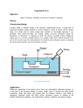
  • 1. Experiment No.2 Objective: Study of Chemical machining and process of chemical machining Theory: Chemicalmachining: Chemical milling or industrial etching is the subtractive manufacturing process of using baths of temperature-regulated etching chemicals to remove material to create an object with the desired shape. It is mostly used on metals, though other materials are increasingly important. It was developed from armor-decorating and printing etching processes developed during the Renaissance as alternatives to engraving on metal. The process essentially involves bathing the cutting areas in a corrosive chemical known as an etchant, which reacts with the material in the area to be cut and causes the solid material to be dissolved; inert substances known as maskants are used to protect specific areas of the material as resists. Figure 1 (Chemical machining) Application: Etching has applications in the printed circuit board and semiconductor fabrication industries. It is also used in the aerospace industry to remove shallow layers of material from large aircraft components, missile skin panels, and extruded parts for airframes. Etching is used widely to manufacture integrated circuits and Micro electro mechanical systems. In addition to the standard, liquid-based techniques, the semiconductor industry commonly uses plasma etching.
  • 2. Process: Chemical milling is normally performed in a series of five steps: cleaning, masking, scribing, etching, and demarking. Cleaning: Cleaning is the preparatory process of ensuring that the surface to be etched is free of contaminants which could negatively impact the quality of the finished part. An improperly cleaned surface could result in poor adhesion of the masking, causing areas to be etched erroneously, or a non-uniform etch rate which could result in inaccurate final dimensions. The surface must be kept free from oils, grease, primer coatings, markings and other residue from the marking out process, scale (oxidation), and any other foreign contaminants. For most metals, this step can be performed by applying a solvent substance to the surface to be etched, washing away foreign contaminants. The material may also be immersed in alkaline oils from human skin could easily contaminate the surface. Masking: Masking is the process of applying the masking material to the surface to ensure that only desired areas are etched. Liquid mask ants may be applied via dip-masking, in which the part is dipped into an open tank of masking and then the mask ant dried. Masking may also be applied by flow coating: liquid masking is flowed over the surface of the part. Certain conductive mask ants may also be applied by electrostatic deposition, where electrical charges are applied to particles of masking as it is sprayed onto the surface of the material. The charge causes the particles of masking to adhere to the surface. Masking types: The masking to be used is determined primarily by the chemical used to etch the material, and the material itself. The masking must adhere to the surface of the material, and it must also be chemically inert enough with regards to the etchant to protect the work piece. Most modern chemical milling processes use maskants with an adhesion around 350 g cm−1; if the adhesion is too strong, the scribing process may be too difficult to perform. If the adhesion is too low, the etching area may be imprecisely defined. Most industrial chemical milling facilities usemaskants based upon neoprene elastomers or isobutylene-isoprene copolymers. Maskants to be used in photochemical machining processes must also possess the necessary light-reactive properties. Scribing: Scribing is the removal of masking on the areas to be etched. For decorative applications, this is often done by hand through the use of a scribing knife, etching needle or similar tool; modern industrial applications may involve an operator scribing with the aid of a template or use computer numerical control to automate the process. For parts involving multiple stages of etching, complex templates using color codes and similar devices may be used.
  • 3. Etching: Etching is the actual immersion of the part into the chemical bath, and the action of the chemical on the part to be milled. The time spent immersed in the chemical bath determines the depth of the resulting etch; this time is calculated via the formula: Where E is the rate of etching (usually abbreviated to etch rate), s is the depth of the cut required, and t is the total immersion time. Etch rate varies based on a number of factors, including the concentration and composition of the etchant, the material to be etched, and temperature conditions. Due to its inconstant nature, etch rate is often determined experimentally immediately prior to the etching process. A small sample of the material to be cut, of the same material specification, heat-treatment condition, and approximately the same thickness is etched for a certain time; after this time, the depth of the etch is measured and used with the time to calculate the etch rate. Aluminum is commonly etched at rates around 0.178 cm/h, and magnesium about 0.46 cm/h. Demarking: Demarking is the combined process of clearing the part of etchant and masking. Etchant is generally removed with a wash of clear, cold water (although other substances may be used in specialized processes). A de-oxidizing bath may also be required in the common case that the etching process left a film of oxide on the surface of the material. Various methods may be used to remove the masking, the most common being simple hand removal using scraping tools. This is frequently both time-consuming and laborious, so for large-scale processes this step may be automated. Advantage:  Complex, concave curvature components can be produced easily by using convex and concave tools.  Tool wear is zero; same tool can be used for producing infinite number of components.  No direct contact between tool and work material so there are no forces and residual stresses.  The surface finish produced is excellent.  Less heat is generated. Disadvantage:  The saline (or acidic) electrolyte poses the risk of corrosion to tool, work piece and equipment.]Only electrically conductive materials can be machined. High Specific Energy consumption. It cannot be used for soft material. Learning outcomes:  The surface finish produced is excellent.  High Specific Energy consumption. It cannot be used for soft material.  Machining is one of the processes of manufacturing in which the specified shape to the work .  Chemical milling is normally performed in a series of five steps: cleaning, masking, scribing, etching, and demarking.
  • 4. Experiment No.3 Objective: Roughing and Finishing Program - Rectangular Pocket Figure 1 (Rectangular Pocket) Theory: Difference between CNC and Conventional Lathes: Conventional Lathe is a 2 axis machine, while a CNC lathe can be 2 - 4 axes. A conventional or manual lathe is just that controlled by your selection of RPM, feed gears; in feed of the compound, cross slide, or carriage is all controlled by levers that engage the feed screw or lead screw. All tools are loaded and changed by hand. Via a regular tool post or a quick change device. Some lathes come with a very accurate Digital Read out or use of dial indicators to measure absolute movement of an axis must be used. A CNC lathe is controlled by a computer numerical control; each axis has a ball screw with a servo motor and encoder to position the machine to within .0001 accuracy or better. It is controlled by G and M codes and Cartesian coordinates; the geometry of the part is programmed in as well as the start diameter of the material and the location of the rough stock sticking out of the chuck in relation to the machine tool vertical and horizontal axis respectively. Each tool in the automatic tool changer must be taught (programmed) in relation to each other tool; the chuck or work piece origin. A CNC lathe may also have milling tool options thus increasing it’s axis count. CNC (Computer Numerical Control) machining is a digital manufacturing technology. It produces high-accuracy parts with excellent physical properties are manufactured directly from a CAD file. Due to the high level of automation, CNC is price-competitive for both one-off custom parts and medium-volume productions. The basic CNC process can be broken down into 3 steps. The engineer first designs the CAD model of the part. The machinists then turn the CAD file into a CNC program (G-code) and sets
  • 5. up the machine. Finally, the CNC system executes all machining operations with little supervision, removing material and creating the part. In turning (lathes), the part is mounted on a rotating chuck and material is removed using stationary cutting tools. This way parts with symmetry along their center axis can be manufactured. Turned parts are typically produced faster (and at a lower cost) than milled parts. Codes of CNC Machine: 1. M Codes:  M00: Program stop  M01: Optional program stop  M02: End of program  M03: Spindle on clockwise  M04: Spindle on counterclockwise  M05: Spindle stop  M06: Tool change  M08: Flood coolant on  M09: Flood coolant off  M30: End of program/return to start  M41: Spindle low gear range  M42: Spindle high gear range 2. G Codes:  G00: Positioning at rapid travel;  G01: Linear interpolation using a feed rate;  G02: Circular interpolation clockwise;  G03: Circular interpolation, counterclockwise;  G04: Dwell  G10: Set working datum position;  G17: Select X-Y plane;  G18: Select Z-X plane;  G19: Select Z-Y plane;  G20: Imperial units;  G21: Metric units;  G27: Reference return check;  G28: Automatic return through reference point;  G29: Move to a location through reference point;  G31: Skip function;  G32: Thread cutting operation on a Lathe;  G33: Thread cutting operation on a Mill;  G40: Cancel cutter compensation;  G41: Cutter compensation left;  G42: Cutter compensation right;
  • 6.  G43: Tool length compensation;  G44: Tool length compensation;  G50: Set coordinate system (Mill) and maximum RPM (Lathe);  G52: Local coordinate system setting;  G53: Machine coordinate system setting;  G54~G59: Set Datum;  G70: Finish cycle (Lathe);  G71: Rough turning cycle (Lathe);  G72: Rough facing cycle (Lathe);  G73: Chip break drilling cycle;  G74: Left hand tapping Mill;  G74: Face grooving cycle;  G75: OD groove pecking cycle (Lathe);  G76: Boring cycle;  G76: Screw cutting cycle (Lathe);  G80: Cancel cycles;  G81: Drill cycle;  G82: Drill cycle with dwell;  G83: Peck drilling cycle;  G84: Tapping cycle;  G85: Bore in, bore out;  G86: Bore in, rapid out;  G87: Back boring cycle;  G90: Absolute programming;  G91: Incremental programming;  G92: Reposition origin point;  G92: Screw thread cutting cycle (Lathe);  G94: Per minute feed;  G95: Per revolution feed;  G96: Constant surface speed (Lathe);  G97: Constant surface speed cancel;  G98: Feed per minute (Lathe);  G99: Feed per revolution (Lathe) Program: [BILLET X75 Y9Ø Z3Ø; [EDGEMOVE X-37.5 Y-45; [TOOLDEF T1 D6 ZØ; OØØØ6; NØØ4Ø G91 G21 G28 XØ YØ ZØ; NØØ5Ø MØ6 TØ1; NØØ6Ø G9Ø GØØ XØ YØ Z1Ø S3ØØØ MØ3;
  • 7. NØØ7Ø GØ1 ZØ F3ØØ; NØØ8Ø G172 I-5Ø J-5Ø KØ PØ Q3 RØ X-25 Y-25 Z-6; NØØ9Ø G173 IØ.5 KØ.1 P75 T1 S3ØØØ R75 F25Ø B35ØØ J2ØØ Z5; NØ1ØØ GØØ Z25 MØ5; NØ11Ø G91 G28 XØ YØ ZØ; NØ12Ø M3Ø; Learning outcomes:  To learn Roughing and Finishing Program - Rectangular Pocket.  Demonstrate the use of operation manuals for the lathes as well as any necessary materials and equipment associated with the CNC lathe.  Demonstrate the proper lubrication of a lathe to manual specifications.  Check the level of the lathe and concentricity of three-jaw chuck with test indicators and align lathe centers by adjusting the tail stock.  Safely and accurately face and center-drill both ends of a work piece on a lathe.  Rough and finish turn a work piece according to print specifications.  Groove and part a work piece to print specifications.
  • 8. Experiment No.4 Objective: One Step Finishing Cycle Program - Rectangular Pocket Figure 1 (Rectangular Pocket) Theory: Difference between CNC and Conventional Lathes: Conventional Lathe is a 2 axis machine, while a CNC lathe can be 2 - 4 axes. A conventional or manual lathe is just that controlled by your selection of RPM, feed gears; in feed of the compound, cross slide, or carriage is all controlled by levers that engage the feed screw or lead screw. All tools are loaded and changed by hand. Via a regular tool post or a quick change device. Some lathes come with a very accurate Digital Read out or use of dial indicators to measure absolute movement of an axis must be used. A CNC lathe is controlled by a computer numerical control; each axis has a ball screw with a servo motor and encoder to position the machine to within .0001 accuracy or better. It is controlled by G and M codes and Cartesian coordinates; the geometry of the part is programmed in as well as the start diameter of the material and the location of the rough stock sticking out of the chuck in relation to the machine tool vertical and horizontal axis respectively. Each tool in the automatic tool changer must be taught (programmed) in relation to each other tool; the chuck or work piece origin. A CNC lathe may also have milling tool options thus increasing it’s axis count. CNC (Computer Numerical Control) machining is a digital manufacturing technology. It produces high-accuracy parts with excellent physical properties are manufactured directly from a CAD file. Due to the high level of automation, CNC is price-competitive for both one-off custom parts and medium-volume productions. The basic CNC process can be broken down into 3 steps. The engineer first designs the CAD
  • 9. model of the part. The machinists then turn the CAD file into a CNC program (G-code) and sets up the machine. Finally, the CNC system executes all machining operations with little supervision, removing material and creating the part. In turning (lathes), the part is mounted on a rotating chuck and material is removed using stationary cutting tools. This way parts with symmetry along their center axis can be manufactured. Turned parts are typically produced faster (and at a lower cost) than milled parts. Codes of CNC Machine: 3. M Codes:  M00: Program stop  M01: Optional program stop  M02: End of program  M03: Spindle on clockwise  M04: Spindle on counterclockwise  M05: Spindle stop  M06: Tool change  M08: Flood coolant on  M09: Flood coolant off  M30: End of program/return to start  M41: Spindle low gear range  M42: Spindle high gear range 4. G Codes:  G00: Positioning at rapid travel;  G01: Linear interpolation using a feed rate;  G02: Circular interpolation clockwise;  G03: Circular interpolation, counterclockwise;  G04: Dwell  G10: Set working datum position;  G17: Select X-Y plane;  G18: Select Z-X plane;  G19: Select Z-Y plane;  G20: Imperial units;  G21: Metric units;  G27: Reference return check;  G28: Automatic return through reference point;  G29: Move to a location through reference point;  G31: Skip function;  G32: Thread cutting operation on a Lathe;  G33: Thread cutting operation on a Mill;  G40: Cancel cutter compensation;  G41: Cutter compensation left;
  • 10.  G42: Cutter compensation right;  G43: Tool length compensation;  G44: Tool length compensation;  G50: Set coordinate system (Mill) and maximum RPM (Lathe);  G52: Local coordinate system setting;  G53: Machine coordinate system setting;  G54~G59: Set Datum;  G70: Finish cycle (Lathe);  G71: Rough turning cycle (Lathe);  G72: Rough facing cycle (Lathe);  G73: Chip break drilling cycle;  G74: Left hand tapping Mill;  G74: Face grooving cycle;  G75: OD groove pecking cycle (Lathe);  G76: Boring cycle;  G76: Screw cutting cycle (Lathe);  G80: Cancel cycles;  G81: Drill cycle;  G82: Drill cycle with dwell;  G83: Peck drilling cycle;  G84: Tapping cycle;  G85: Bore in, bore out;  G86: Bore in, rapid out;  G87: Back boring cycle;  G90: Absolute programming;  G91: Incremental programming;  G92: Reposition origin point;  G92: Screw thread cutting cycle (Lathe);  G94: Per minute feed;  G95: Per revolution feed;  G96: Constant surface speed (Lathe);  G97: Constant surface speed cancel;  G98: Feed per minute (Lathe);  G99: Feed per revolution (Lathe) Program: [BILLET X75 Y90 Z30; [EDGEMOVE X-37.5 Y-45; [TOOLDEF T1 D6 Z0; O0007; NØØ4Ø G91 G21 G28 X0 Y0 Z0; NØØ4Ø M06 T01;
  • 11. NØØ4Ø G90 G00 X0 Y0 Z10 S3000 M03; NØØ4Ø G01 Z0 F300; NØØ4Ø G172 I-50 J-50 K0 P1 Q3 R0 X-25 Y-25 Z-6; NØØ4Ø G173 I0.5 K0.1 P75 T1 S3000 R75 F250 B3500 J200 Z5; NØØ4Ø G00 Z25 M05; NØØ4Ø G91 G28 X0 Y0 Z0; NØØ4Ø M30; Learning outcomes:  Reference return check.  Automatic return through reference point.  Move to a location through reference point.  One Step Finishing Cycle Program - Rectangular Pocket.
  • 12. Experiment No.5 Objective: Write a G-Code Program for the Part Shown Below Figure 1 Theory: Difference between CNC and Conventional Lathes: Conventional Lathe is a 2 axis machine, while a CNC lathe can be 2 - 4 axes. A conventional or manual lathe is just that controlled by your selection of RPM, feed gears; in feed of the compound, cross slide, or carriage is all controlled by levers that engage the feed screw or lead screw. All tools are loaded and changed by hand. Via a regular tool post or a quick change device. Some lathes come with a very accurate Digital Read out or use of dial indicators to measure absolute movement of an axis must be used. A CNC lathe is controlled by a computer numerical control; each axis has a ball screw with a servo motor and encoder to position the machine to within .0001 accuracy or better. It is controlled by G and M codes and Cartesian coordinates; the geometry of the part is programmed in as well as the start diameter of the material and the location of the rough stock sticking out of the chuck in relation to the machine tool vertical and horizontal axis respectively. Each tool in the automatic tool changer must be taught (programmed) in relation to each other tool; the chuck or work piece origin. A CNC lathe may also have milling tool options thus increasing its axis count. CNC (Computer Numerical Control) machining is a digital manufacturing technology. It produces high-accuracy parts with excellent physical properties are manufactured directly from a CAD file. Due to the high level of automation, CNC is price-competitive for both one-off custom
  • 13. parts and medium-volume productions. The basic CNC process can be broken down into 3 steps. The engineer first designs the CAD model of the part. The machinists then turn the CAD file into a CNC program (G-code) and sets up the machine. Finally, the CNC system executes all machining operations with little supervision, removing material and creating the part. In turning (lathes), the part is mounted on a rotating chuck and material is removed using stationary cutting tools. This way parts with symmetry along their center axis can be manufactured. Turned parts are typically produced faster (and at a lower cost) than milled parts. Codes of CNC Machine: 5. M Codes:  M00: Program stop  M01: Optional program stop  M02: End of program  M03: Spindle on clockwise  M04: Spindle on counterclockwise  M05: Spindle stop  M06: Tool change  M08: Flood coolant on  M09: Flood coolant off  M30: End of program/return to start  M41: Spindle low gear range  M42: Spindle high gear range 6. G Codes:  G00: Positioning at rapid travel;  G01: Linear interpolation using a feed rate;  G02: Circular interpolation clockwise;  G03: Circular interpolation, counterclockwise;  G04: Dwell  G10: Set working datum position;  G17: Select X-Y plane;  G18: Select Z-X plane;  G19: Select Z-Y plane;  G20: Imperial units;  G21: Metric units;  G27: Reference return check;  G28: Automatic return through reference point;  G29: Move to a location through reference point;  G31: Skip function;  G32: Thread cutting operation on a Lathe;
  • 14.  G33: Thread cutting operation on a Mill;  G40: Cancel cutter compensation;  G41: Cutter compensation left;  G42: Cutter compensation right;  G43: Tool length compensation;  G44: Tool length compensation;  G50: Set coordinate system (Mill) and maximum RPM (Lathe);  G52: Local coordinate system setting;  G53: Machine coordinate system setting;  G54~G59: Set Datum;  G70: Finish cycle (Lathe);  G71: Rough turning cycle (Lathe);  G72: Rough facing cycle (Lathe);  G73: Chip break drilling cycle;  G74: Left hand tapping Mill;  G74: Face grooving cycle;  G75: OD groove pecking cycle (Lathe);  G76: Boring cycle;  G76: Screw cutting cycle (Lathe);  G80: Cancel cycles;  G81: Drill cycle;  G82: Drill cycle with dwell;  G83: Peck drilling cycle;  G84: Tapping cycle;  G85: Bore in, bore out;  G86: Bore in, rapid out;  G87: Back boring cycle;  G90: Absolute programming;  G91: Incremental programming;  G92: Reposition origin point;  G92: Screw thread cutting cycle (Lathe);  G94: Per minute feed;  G95: Per revolution feed;  G96: Constant surface speed (Lathe);  G97: Constant surface speed cancel;  G98: Feed per minute (Lathe);  G99: Feed per revolution (Lathe) Program: N010 G70G90G94G97M04 N020 G17G75F6.0 S300 T1001 M08
  • 15. N030 G01X3.875 Y3.698 N040 G01X3.875 Y9.125 N050 G01X5.634 Y9.125 N060 G03X7.366 Y9.125 I6.5 J9.0 N070 G01X9.302 N080 G01X3.875 Y3.698 N090 G01X2.0 Y2.0 M30 N100 M00 Learning outcomes:  To learn about CNC and Conventional Lathes different operating programs.  CNC lathe is controlled by a computer numerical control, each axis has a ball Conventional Lathe is a 2 axis machine.  While a CNC lathe can be 2 - 4 axis.  Some lathes come with a very accurate Digital Read out or use of dial indicators to measure absolute movement of an axis must be used.
  • 16. Experiment No.6 Objective: A typical round part used for CNC programming and machining. Figure 1 (round part) Theory: Difference between CNC and Conventional Lathes: Conventional Lathe is a 2 axis machine, while a CNC lathe can be 2 - 4 axes. A conventional or manual lathe is just that controlled by your selection of RPM, feed gears; in feed of the compound, cross slide, or carriage is all controlled by levers that engage the feed screw or lead screw. All tools are loaded and changed by hand. Via a regular tool post or a quick change device. Some lathes come with a very accurate Digital Read out or use of dial indicators to measure absolute movement of an axis must be used. A CNC lathe is controlled by a computer numerical control; each axis has a ball screw with a servo motor and encoder to position the machine to within .0001 accuracy or better. It is controlled by G and M codes and Cartesian coordinates; the geometry of the part is programmed in as well as the start diameter of the material and the location of the rough stock sticking out of the chuck in relation to the machine tool vertical and horizontal axis respectively. Each tool in the automatic tool changer must be taught (programmed) in relation to each other tool; the chuck or work piece origin. A CNC lathe may also have milling tool options thus increasing it’s axis count. CNC (Computer Numerical Control) machining is a digital manufacturing technology. It produces high-accuracy parts with excellent physical properties are manufactured directly from a CAD file. Due to the high level of automation, CNC is price-competitive for both one-off custom parts and medium-volume productions.
  • 17. The basic CNC process can be broken down into 3 steps. The engineer first designs the CAD model of the part. The machinists then turn the CAD file into a CNC program (G-code) and sets up the machine. Finally, the CNC system executes all machining operations with little supervision, removing material and creating the part. In turning (lathes), the part is mounted on a rotating chuck and material is removed using stationary cutting tools. This way parts with symmetry along their center axis can be manufactured. Turned parts are typically produced faster (and at a lower cost) than milled parts. Codes of CNC Machine: 7. M Codes:  M00: Program stop  M01: Optional program stop  M02: End of program  M03: Spindle on clockwise  M04: Spindle on counterclockwise  M05: Spindle stop  M06: Tool change  M08: Flood coolant on  M09: Flood coolant off  M30: End of program/return to start  M41: Spindle low gear range  M42: Spindle high gear range 8. G Codes:  G00: Positioning at rapid travel;  G01: Linear interpolation using a feed rate;  G02: Circular interpolation clockwise;  G03: Circular interpolation, counterclockwise;  G04: Dwell  G10: Set working datum position;  G17: Select X-Y plane;  G18: Select Z-X plane;  G19: Select Z-Y plane;  G20: Imperial units;  G21: Metric units;  G27: Reference return check;  G28: Automatic return through reference point;  G29: Move to a location through reference point;  G31: Skip function;  G32: Thread cutting operation on a Lathe;  G33: Thread cutting operation on a Mill;  G40: Cancel cutter compensation;
  • 18.  G41: Cutter compensation left;  G42: Cutter compensation right;  G43: Tool length compensation;  G44: Tool length compensation;  G50: Set coordinate system (Mill) and maximum RPM (Lathe);  G52: Local coordinate system setting;  G53: Machine coordinate system setting;  G54~G59: Set Datum;  G70: Finish cycle (Lathe);  G71: Rough turning cycle (Lathe);  G72: Rough facing cycle (Lathe);  G73: Chip break drilling cycle;  G74: Left hand tapping Mill;  G74: Face grooving cycle;  G75: OD groove pecking cycle (Lathe);  G76: Boring cycle;  G76: Screw cutting cycle (Lathe);  G80: Cancel cycles;  G81: Drill cycle;  G82: Drill cycle with dwell;  G83: Peck drilling cycle;  G84: Tapping cycle;  G85: Bore in, bore out;  G86: Bore in, rapid out;  G87: Back boring cycle;  G90: Absolute programming;  G91: Incremental programming;  G92: Reposition origin point;  G92: Screw thread cutting cycle (Lathe);  G94: Per minute feed;  G95: Per revolution feed;  G96: Constant surface speed (Lathe);  G97: Constant surface speed cancel;  G98: Feed per minute (Lathe);  G99: Feed per revolution (Lathe) Program: Turning Programming Programming Sequence N05 G20 G90 G40
  • 19. N10 G95 G96 S2000 M03 N15 T0202 N20 G00 X1.200 Z.100 Rough Turning Cycle N25 G73 U.05 R.05 N30 G73 P35 Q95 U.025 W.005 F.008 N35 G00 X.300 Z.050 N40 G01 Z0 N45 G03 X.500 Z-.100 R.100 N50 G01 Z-.650 N55 X.580 N60 X.700 Z-.710 N65 Z-1.150 N75 X.875 Z-1.800 (cutting taper) N80 X.925 Finish Turning N100 G72 P35 Q95 F.005 N105 G00 X2.000 Z.500 N110 M30 Learning outcomes:  Extremelyexpensive bymechanical means (whichusuallywouldrequire complex jigstocontrol threadforms  Gothic arc  Circular arc.  ThreadForm
  • 20. Experiment No.7 Objective: Circular pocket cutting Figure 1 (Circular pocket cutting) Theory: Difference between CNC and Conventional Lathes: Conventional Lathe is a 2 axis machine, while a CNC lathe can be 2 - 4 axes. A conventional or manual lathe is just that controlled by your selection of RPM, feed gears; in feed of the compound, cross slide, or carriage is all controlled by levers that engage the feed screw or lead screw. All tools are loaded and changed by hand. Via a regular tool post or a quick change device. Some lathes come with a very accurate Digital Read out or use of dial indicators to measure absolute movement of an axis must be used. A CNC lathe is controlled by a computer numerical control; each axis has a ball screw with a servo motor and encoder to position the machine to within .0001 accuracy or better. It is controlled by G and M codes and Cartesian coordinates; the geometry of the part is programmed in as well as the start diameter of the material and the location of the rough stock sticking out of the chuck in relation to the machine tool vertical and horizontal axis respectively. Each tool in the automatic tool changer must be taught (programmed) in relation to each other tool; the chuck or work piece origin. A CNC lathe may also have milling tool options thus increasing its axis count. CNC (Computer Numerical Control) machining is a digital manufacturing technology. It produces high-accuracy parts with excellent physical properties are manufactured directly from a
  • 21. CAD file. Due to the high level of automation, CNC is price-competitive for both one-off custom parts and medium-volume productions. The basic CNC process can be broken down into 3 steps. The engineer first designs the CAD model of the part. The machinists then turn the CAD file into a CNC program (G-code) and sets up the machine. Finally, the CNC system executes all machining operations with little supervision, removing material and creating the part. In turning (lathes), the part is mounted on a rotating chuck and material is removed using stationary cutting tools. This way parts with symmetry along their center axis can be manufactured. Turned parts are typically produced faster (and at a lower cost) than milled parts. Codes of CNC Machine: 9. M Codes:  M00: Program stop  M01: Optional program stop  M02: End of program  M03: Spindle on clockwise  M04: Spindle on counterclockwise  M05: Spindle stop  M06: Tool change  M08: Flood coolant on  M09: Flood coolant off  M30: End of program/return to start  M41: Spindle low gear range  M42: Spindle high gear range 10. G Codes:  G00: Positioning at rapid travel;  G01: Linear interpolation using a feed rate;  G02: Circular interpolation clockwise;  G03: Circular interpolation, counterclockwise;  G04: Dwell  G10: Set working datum position;  G17: Select X-Y plane;  G18: Select Z-X plane;  G19: Select Z-Y plane;  G20: Imperial units;  G21: Metric units;  G27: Reference return check;  G28: Automatic return through reference point;  G29: Move to a location through reference point;  G31: Skip function;
  • 22.  G32: Thread cutting operation on a Lathe;  G33: Thread cutting operation on a Mill;  G40: Cancel cutter compensation;  G41: Cutter compensation left;  G42: Cutter compensation right;  G43: Tool length compensation;  G44: Tool length compensation;  G50: Set coordinate system (Mill) and maximum RPM (Lathe);  G52: Local coordinate system setting;  G53: Machine coordinate system setting;  G54~G59: Set Datum;  G70: Finish cycle (Lathe);  G71: Rough turning cycle (Lathe);  G72: Rough facing cycle (Lathe);  G73: Chip break drilling cycle;  G74: Left hand tapping Mill;  G74: Face grooving cycle;  G75: OD groove pecking cycle (Lathe);  G76: Boring cycle;  G76: Screw cutting cycle (Lathe);  G80: Cancel cycles;  G81: Drill cycle;  G82: Drill cycle with dwell;  G83: Peck drilling cycle;  G84: Tapping cycle;  G85: Bore in, bore out;  G86: Bore in, rapid out;  G87: Back boring cycle;  G90: Absolute programming;  G91: Incremental programming;  G92: Reposition origin point;  G92: Screw thread cutting cycle (Lathe);  G94: Per minute feed;  G95: Per revolution feed;  G96: Constant surface speed (Lathe);  G97: Constant surface speed cancel;  G98: Feed per minute (Lathe);  G99: Feed per revolution (Lathe) Program: N29 X33.0 Y32.5 (A) N30 G01 Z-5.0 Z100.0
  • 23. N31 G41 X35.0 Y19.5 D62 F175.0 (B) N32 G03 X48.0 Y32.5 I0 J13.0 ©) N33 I-15.0 (D) N34 X35.0 Y45.5 I-13.0 J0 (E) N35 G40 G01 X33.0 Y32.5 (A) N36 G00 Z10.0 M09 N37 G28 Z10.0 M05 N38 M01 Learning outcomes:  The highest possible surface quality.  Minimum tool wear.  Shortest time machining.  Low cost of production.  Minimum energy use.
  • 24. Experiment No.8 Objective: Slot milling Figure 2 (Slot milling) Theory: Difference between CNC and Conventional Lathes: Conventional Lathe is a 2 axis machine, while a CNC lathe can be 2 - 4 axes. A conventional or manual lathe is just that controlled by your selection of RPM, feed gears; in feed of the compound, cross slide, or carriage is all controlled by levers that engage the feed screw or lead screw. All tools are loaded and changed by hand. Via a regular tool post or a quick change device. Some lathes come with a very accurate Digital Read out or use of dial indicators to measure absolute movement of an axis must be used. A CNC lathe is controlled by a computer numerical control; each axis has a ball screw with a servo motor and encoder to position the machine to within .0001 accuracy or better. It is controlled by G and M codes and Cartesian coordinates; the geometry of the part is programmed in as well as the start diameter of the material and the location of the rough stock sticking out of the chuck in relation to the machine tool vertical and horizontal axis respectively. Each tool in the automatic tool changer must be taught (programmed) in relation to each other tool; the chuck or work piece origin. A CNC lathe may also have milling tool options thus increasing its axis count.
  • 25. CNC (Computer Numerical Control) machining is a digital manufacturing technology. It produces high-accuracy parts with excellent physical properties are manufactured directly from a CAD file. Due to the high level of automation, CNC is price-competitive for both one-off custom parts and medium-volume productions. The basic CNC process can be broken down into 3 steps. The engineer first designs the CAD model of the part. The machinists then turn the CAD file into a CNC program (G-code) and sets up the machine. Finally, the CNC system executes all machining operations with little supervision, removing material and creating the part. In turning (lathes), the part is mounted on a rotating chuck and material is removed using stationary cutting tools. This way parts with symmetry along their center axis can be manufactured. Turned parts are typically produced faster (and at a lower cost) than milled parts. Codes of CNC Machine: 11. M Codes:  M00: Program stop  M01: Optional program stop  M02: End of program  M03: Spindle on clockwise  M04: Spindle on counterclockwise  M05: Spindle stop  M06: Tool change  M08: Flood coolant on  M09: Flood coolant off  M30: End of program/return to start  M41: Spindle low gear range  M42: Spindle high gear range 12. G Codes:  G00: Positioning at rapid travel;  G01: Linear interpolation using a feed rate;  G02: Circular interpolation clockwise;  G03: Circular interpolation, counterclockwise;  G04: Dwell  G10: Set working datum position;  G17: Select X-Y plane;  G18: Select Z-X plane;  G19: Select Z-Y plane;  G20: Imperial units;  G21: Metric units;  G27: Reference return check;  G28: Automatic return through reference point;  G29: Move to a location through reference point;
  • 26.  G31: Skip function;  G32: Thread cutting operation on a Lathe;  G33: Thread cutting operation on a Mill;  G40: Cancel cutter compensation;  G41: Cutter compensation left;  G42: Cutter compensation right;  G43: Tool length compensation;  G44: Tool length compensation;  G50: Set coordinate system (Mill) and maximum RPM (Lathe);  G52: Local coordinate system setting;  G53: Machine coordinate system setting;  G54~G59: Set Datum;  G70: Finish cycle (Lathe);  G71: Rough turning cycle (Lathe);  G72: Rough facing cycle (Lathe);  G73: Chip break drilling cycle;  G74: Left hand tapping Mill;  G74: Face grooving cycle;  G75: OD groove pecking cycle (Lathe);  G76: Boring cycle;  G76: Screw cutting cycle (Lathe);  G80: Cancel cycles;  G81: Drill cycle;  G82: Drill cycle with dwell;  G83: Peck drilling cycle;  G84: Tapping cycle;  G85: Bore in, bore out;  G86: Bore in, rapid out;  G87: Back boring cycle;  G90: Absolute programming;  G91: Incremental programming;  G92: Reposition origin point;  G92: Screw thread cutting cycle (Lathe);  G94: Per minute feed;  G95: Per revolution feed;  G96: Constant surface speed (Lathe);  G97: Constant surface speed cancel;  G98: Feed per minute (Lathe);  G99: Feed per revolution (Lathe) Program: (T03 - 8 MM CENTER-CUTTING E/MILL)
  • 27. (D53 = 4.000) N39 T03 N40 M06 N41 G90 G54 G00 X73.0 Y50.0 S2188 M03 T04 N42 G43 Z10.0 H03 M08 N43 Z2.0 N44 G01 Z-3.0 F100.0 N45 Y15.0 F263.0 Learning outcomes:  Groove or slot milling is an operation in which side and face milling is often preferred to end milling.  Slots or grooves can be short or long, closed or open, straight or non-straight, deep or shallow, wide or narrow.  Tool selection is normally determined by the width and depth of the groove and, to some extent, length.
  • 28. Experiment No.9 Objective: Slot finishing Figure1 (Slot finishing) Theory: Difference between CNC and Conventional Lathes: Conventional Lathe is a 2 axis machine, while a CNC lathe can be 2 - 4 axes. A conventional or manual lathe is just that controlled by your selection of RPM, feed gears; in feed of the compound, cross slide, or carriage is all controlled by levers that engage the feed screw or lead screw. All tools are loaded and changed by hand. Via a regular tool post or a quick change device. Some lathes come with a very accurate Digital Read out or use of dial indicators to measure absolute movement of an axis must be used. A CNC lathe is controlled by a computer numerical control; each axis has a ball screw with a servo motor and encoder to position the machine to within .0001 accuracy or better. It is controlled by G and M codes and Cartesian coordinates; the geometry of the part is programmed in as well as the start diameter of the material and the location of the rough stock sticking out of the chuck in relation to the machine tool vertical and horizontal axis respectively. Each tool in the automatic tool changer must be taught (programmed) in relation to each other tool; the chuck or work piece origin. A CNC lathe may also have milling tool options thus increasing its axis count. CNC (Computer Numerical Control) machining is a digital manufacturing technology. It produces high-accuracy parts with excellent physical properties are manufactured directly from a
  • 29. CAD file. Due to the high level of automation, CNC is price-competitive for both one-off custom parts and medium-volume productions. The basic CNC process can be broken down into 3 steps. The engineer first designs the CAD model of the part. The machinists then turn the CAD file into a CNC program (G-code) and sets up the machine. Finally, the CNC system executes all machining operations with little supervision, removing material and creating the part. In turning (lathes), the part is mounted on a rotating chuck and material is removed using stationary cutting tools. This way parts with symmetry along their center axis can be manufactured. Turned parts are typically produced faster (and at a lower cost) than milled parts. Codes of CNC Machine: 13. M Codes:  M00: Program stop  M01: Optional program stop  M02: End of program  M03: Spindle on clockwise  M04: Spindle on counterclockwise  M05: Spindle stop  M06: Tool change  M08: Flood coolant on  M09: Flood coolant off  M30: End of program/return to start  M41: Spindle low gear range  M42: Spindle high gear range 14. G Codes:  G00: Positioning at rapid travel;  G01: Linear interpolation using a feed rate;  G02: Circular interpolation clockwise;  G03: Circular interpolation, counterclockwise;  G04: Dwell  G10: Set working datum position;  G17: Select X-Y plane;  G18: Select Z-X plane;  G19: Select Z-Y plane;  G20: Imperial units;  G21: Metric units;  G27: Reference return check;  G28: Automatic return through reference point;  G29: Move to a location through reference point;  G31: Skip function;
  • 30.  G32: Thread cutting operation on a Lathe;  G33: Thread cutting operation on a Mill;  G40: Cancel cutter compensation;  G41: Cutter compensation left;  G42: Cutter compensation right;  G43: Tool length compensation;  G44: Tool length compensation;  G50: Set coordinate system (Mill) and maximum RPM (Lathe);  G52: Local coordinate system setting;  G53: Machine coordinate system setting;  G54~G59: Set Datum;  G70: Finish cycle (Lathe);  G71: Rough turning cycle (Lathe);  G72: Rough facing cycle (Lathe);  G73: Chip break drilling cycle;  G74: Left hand tapping Mill;  G74: Face grooving cycle;  G75: OD groove pecking cycle (Lathe);  G76: Boring cycle;  G76: Screw cutting cycle (Lathe);  G80: Cancel cycles;  G81: Drill cycle;  G82: Drill cycle with dwell;  G83: Peck drilling cycle;  G84: Tapping cycle;  G85: Bore in, bore out;  G86: Bore in, rapid out;  G87: Back boring cycle;  G90: Absolute programming;  G91: Incremental programming;  G92: Reposition origin point;  G92: Screw thread cutting cycle (Lathe);  G94: Per minute feed;  G95: Per revolution feed;  G96: Constant surface speed (Lathe);  G97: Constant surface speed cancel;  G98: Feed per minute (Lathe);  G99: Feed per revolution (Lathe) Program: N46 G41 X73.5 Y10.5 D53 N47 G03 X78.0 Y15.0 I0 J4.5
  • 31. N48 G01 Y50.0 N49 G03 X68.0 I-5.0 J0 N50 G01 Y15.0 N51 G03 X78.0 I5.0 J0 N52 X73.5 Y19.5 I-4.5 J0 N53 G40 G01 X73.0 Y15.0 N54 G00 Z10.0 M09 N55 G28 Z10.0 M05 N56 M01 Learning outcomes:  Groove or slot milling is an operation in which side and face milling is often preferred to end milling.  Slots or grooves can be short or long, closed or open, straight or non-straight, deep or shallow, wide or narrow.  Tool selection is normally determined by the width and depth of the groove and, to some extent, length.  Super finishing process.