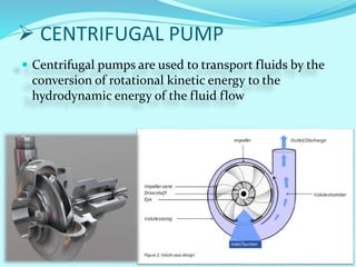
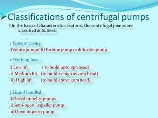
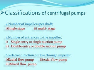
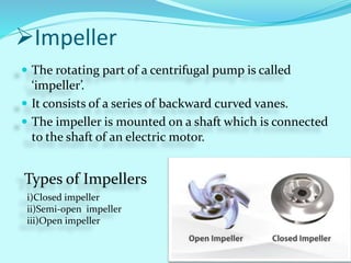
Presented By:- Guided by:-
B. Rajeshwari
Chetan lal thakur
Chitrangad sahu
Damini sahu
Daneshwar singh thakur
Mr. Gajendra Dewangan
•Centrifugal pump
•Classifications of centrifugal pumps
•Types of Impellers
•Casings
•Stages
•Couplings
 CENTRIFUGAL PUMP
 Centrifugal pumps are used to transport fluids by the
conversion of rotational kinetic energy to the
hydrodynamic energy of the fluid flow
Classifications of centrifugal pumps
On the basis of characteristics features, the centrifugal pumps are
classified as follows:
1.Types of casing;
i)Volute pumps ii)Turbine pump or diffusion pump
2.Working head;
i) Low lift ( to build upto 15m head)
ii) Medium lift (to build as high as 40m head)
iii) High lift (to build above 40m head)
3.Liquid handled;
i)Closed impeller pumps
ii)Semi-open impeller pump
iii)Open impeller pump
4.Number of impellers per shaft;
i)Single stage ii) multi- stage
5.Number of entrances to the impeller;
i) Single entry or single suction pump
ii) Double entry or double suction pump
6.Relative direction of flow through impeller;
i)Radial flow pump ii)Axial flow pump
iii)Mixed flow pump
Classifications of centrifugal pumps
Impeller
 The rotating part of a centrifugal pump is called
‘impeller’.
 It consists of a series of backward curved vanes.
 The impeller is mounted on a shaft which is connected
to the shaft of an electric motor.
Types of Impellers
i)Closed impeller
ii)Semi-open impeller
iii)Open impeller
Casing
 It is an air tight passage surrounding the impeller.
 It is designed in such a way that the kinetic energy of
the water discharged at the outlet of the impeller is
converted into pressure energy before the water leaves
the casing
Types of casing;
i) Volute casing
ii) Vortex casing
iii)Casing with guide
blades
Stages
Types of stages in centrifugal pumps
Multi stageSingle stage
Consisting one impeller Consisting two or more impellers
Connected in series Connected in parallel
Used to develop high
head
Used for discharging
large quantity of liquid
Most widely used in
production operation
Fig.(A) Fig.(B)
Fig.(A)
Fig.(B)
Impellers Connected in series
Impellers Connected in parallel
Coupling
 A coupling is a device used to connect two shafts
together at their ends for the purpose of transmitting
power.
Shaft coupling
Misalignment type
Coupling type
Double-cardanic coupling for
compensating shaft offset
Curved-tooth gear coupling
Spacer –type coupling
Uses of Couplings
THANK YOU

Centrifugal pump

  • 1.
    Presented By:- Guidedby:- B. Rajeshwari Chetan lal thakur Chitrangad sahu Damini sahu Daneshwar singh thakur Mr. Gajendra Dewangan
  • 2.
    •Centrifugal pump •Classifications ofcentrifugal pumps •Types of Impellers •Casings •Stages •Couplings
  • 3.
     CENTRIFUGAL PUMP Centrifugal pumps are used to transport fluids by the conversion of rotational kinetic energy to the hydrodynamic energy of the fluid flow
  • 4.
    Classifications of centrifugalpumps On the basis of characteristics features, the centrifugal pumps are classified as follows: 1.Types of casing; i)Volute pumps ii)Turbine pump or diffusion pump 2.Working head; i) Low lift ( to build upto 15m head) ii) Medium lift (to build as high as 40m head) iii) High lift (to build above 40m head) 3.Liquid handled; i)Closed impeller pumps ii)Semi-open impeller pump iii)Open impeller pump
  • 5.
    4.Number of impellersper shaft; i)Single stage ii) multi- stage 5.Number of entrances to the impeller; i) Single entry or single suction pump ii) Double entry or double suction pump 6.Relative direction of flow through impeller; i)Radial flow pump ii)Axial flow pump iii)Mixed flow pump Classifications of centrifugal pumps
  • 6.
    Impeller  The rotatingpart of a centrifugal pump is called ‘impeller’.  It consists of a series of backward curved vanes.  The impeller is mounted on a shaft which is connected to the shaft of an electric motor. Types of Impellers i)Closed impeller ii)Semi-open impeller iii)Open impeller
  • 7.
    Casing  It isan air tight passage surrounding the impeller.  It is designed in such a way that the kinetic energy of the water discharged at the outlet of the impeller is converted into pressure energy before the water leaves the casing Types of casing; i) Volute casing ii) Vortex casing iii)Casing with guide blades
  • 8.
    Stages Types of stagesin centrifugal pumps Multi stageSingle stage Consisting one impeller Consisting two or more impellers Connected in series Connected in parallel Used to develop high head Used for discharging large quantity of liquid Most widely used in production operation Fig.(A) Fig.(B)
  • 9.
    Fig.(A) Fig.(B) Impellers Connected inseries Impellers Connected in parallel
  • 10.
    Coupling  A couplingis a device used to connect two shafts together at their ends for the purpose of transmitting power. Shaft coupling Misalignment type
  • 11.
    Coupling type Double-cardanic couplingfor compensating shaft offset
  • 12.
  • 13.
  • 14.