
Recommended
More Related Content
What's hot
What's hot (20)
Similar to Quick return mechanism11
Similar to Quick return mechanism11 (20)
More from Saif al-din ali
More from Saif al-din ali (20)
Recently uploaded
Recently uploaded (20)
Quick return mechanism11
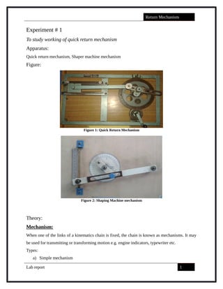
- 1. Return Mechanism Experiment # 1 To study working of quick return mechanism Apparatus: Quick return mechanism, Shaper machine mechanism Figure: Figure 1: Quick Return Mechanism Figure 2: Shaping Machine mechanism Theory: Mechanism: When one of the links of a kinematics chain is fixed, the chain is known as mechanisms. It may be used for transmitting or transforming motion e.g. engine indicators, typewriter etc. Types: a) Simple mechanism Lab report 1 saif alden ali saif alden ali
- 2. Return Mechanism b) Compound mechanism a) Simple Mechanism: A mechanism with four links is known as simple mechanism. b) Compound Mechanism: The mechanism with more than four links is known as compound mechanism. Machine: When a mechanism is required to transmit power or to some particular type of work; it then becomes a machine. In such cases the links is to be designed to withstand the force (both static and kinetic safely) A little consideration will show that a mechanism may be regarded as a machine in which each part is reduced to the simplest form to transmit the required motion. Inversion: Sometimes, one of the links in a kinematic chain is fixed. In such a case, we may obtain as many mechanisms as the links of the kinematic chain. This method of obtaining different mechanisms, by fixing in turns different links in a kinematic chain, is known as inversion. Types of kinematic chains: The most important kinematic chains are those which consist of four lower pairs, each pair being a sliding pair or a turning pair. The following types of kinematic chain are important from subject point of view: a. Four bar chain or quadratic cycle chain 1. Beam engine 2. Coupling rod of locomotive 3. Watt’s indicator mechanism b. Single slider crank chain 1. Pendulum pump 2. Oscillating cylinder engine 3. Quick return motion mechanism 4. Rotary I.C. engine (Gnome engine) c. Double slider crank chain Four bar chain: Lab report 2 saif alden ali saif alden ali saif alden ali
- 3. Return Mechanism A kinematic chain which consists of four links is known as four bar chain. In four bar chain each of four pairs is a turning pair. These links may or may not have same length. If link AB is fixed and a small displacement is given to link AD the resulting displacement of link BC and CD are also definite. So, this shows that the relative motion is completely constrained. The structure of simple kinematic chains is derived from simple four bar chain. Sometimes a link is added which will form a turning pair with existing link and also themselves form a pair. Compound kinematic chain: If a kinematic chain has more than four pairs it is known as Compound kinematic chain. Inversions of four bar chain: The practical application of a four bar chain are found in: 1. Beam engine (Crank and lever mechanism) 2. Coupling rod of locomotive (Double crank mechanism) 3. Watt’s indicator mechanism (Double lever mechanism) 1. Beam engine: A part of the mechanism is shown in the figure. It consists of four links and is also known as crank and lever mechanism. Lab report 3 saif alden ali saif alden ali saif alden ali
- 4. Return Mechanism In this mechanism the lever oscillates about a fixed centre D while crank rotates about a fixed centre A. The end E of lever CDE is connected to a piston rod, which reciprocates due to rotation of the crank. In other words the purpose of this mechanism is to convert rotatory motion to reciprocating motion. 2. Coupling rod of locomotive: The mechanism of a coupling rod of locomotive consists of four links as shown in figure: In this mechanism, the links AD and BC acts as cranks connected to the respective wheels and the link CD acts as a coupling rod. The link AB is fixed in order to maintain a constant centre to centre distance between them. 3. Watt’s indicator mechanism: A watt’s indicator mechanism which consists of four links is shown in figure: Lab report 4 saif alden ali saif alden ali saif alden ali
- 5. Return Mechanism The four links are: Fixed link at A Link AC Link CE Link BFD It may be noted that BD and FD form as one link because these two parts have no relative motion between them. The links CE and BFD acts as levers. On any small displacement of the mechanism the tracing point E traces out approximately a straight line. The initial position of mechanism is shown by solid lines whereas dotted lines show the position of mechanism when gas or steam pressure acts on the indicator. Single slider crank chain: A slider crank chain consists of one sliding pair and three turning pairs. It is, usually, found in reciprocating steam engine mechanism. These types of mechanisms convert rotary motion into reciprocating motion and vice versa. In a single slider crank chain, as shown in fig. P1, P2, and P3 are called turning pairs while P4 is sliding pair. Lab report 5 saif alden ali saif alden ali saif alden ali
- 6. Return Mechanism The link 1 corresponds to the frame of engine, which is fixed. The link 2 corresponds to the crank; link 3 corresponds to cross head. As the crank rotates, the cross head reciprocates in the guides. Inversions of slider crank chain: Slider crank is a 4-link mechanism. We know that by fixing, in turn, different links in a kinematic links in a kinematic chain, an inversion is obtained and we can obtain as many mechanisms as the links in the kinematic chain. It is thus obvious, that four inversions are possible. These inversions are in following mechanism. 1. Pendulum Pump or Bull Engine 2. Oscillating Cylinder Engine 3. Crank and Slotted Lever Quick Return Motion Mechanism 4. Whitworth’s quick return mechanism 5. Quick Return I.C. Engine 1. Pendulum pump or bull engine: In this mechanism is obtained by fixing the cylinder or link as shown in fig. In this case when link 2 rotates, the piston in link 1 reciprocates and link 3 oscillates. This mechanism is of little importance from practical point of view. 2. Oscillating Cylinder Engine: Lab report 6 saif alden ali saif alden ali saif alden ali
- 7. Return Mechanism The arrangement of oscillating cylinder engine mechanism as shown: In this type of mechanism, link 3 is fixed. As link 2 (crank) rotates, link 1 reciprocates and link 4 oscillates, which is pivoted to link fixed at A. The link 3 corresponds to connecting rod in reciprocating engine mechanism. 3. Crank and slotted lever quick return motion mechanism: This mechanism is mostly used in shaping machine, slotting machine and in rotary internal combustion engine. The mechanism consists of a fixed link AC as shown in fig. The driving crank revolves with uniform angular speed about the fixed center C.A sliding block attached to the crank pin at E slides along the slotted bar AP and thus causes AP to oscillate about Lab report 7 saif alden ali saif alden ali saif alden ali saif alden ali
- 8. Return Mechanism the fixed center A. A short link bar PR transmit the motion from AP to the ram which carries the tool and reciprocates along the line of stroke R 1 R2. The line of stroke of the ram (R 1 R2) is perpendicular to AO produced. In the extreme position, AP and AP2 are tangential to the circle and the cutting tool is at the end of the stroke. The cutting stroke occurs when the crank rotates from the position CB1 to CB2 (or through an angle beta) in the clockwise direction. The return stroke occurs when the crank rotates from the position CB2to CB1 (or through an angle alpha) in the clockwise direction. 4. Whitworth’s quick return mechanism: This mechanism is mostly used in shaping machine; slotting machine. It is obtained by fixing the link 2 as shown in fig 5.14. In this mechanism, the driving crank CA (link 3) rotates at uniform angular speed. The slider (link 4) slides in a slot in a slotted lever PA (link 1) which is pivoted a fixed point D. The connecting rood PR carries the ram at R, to which a cutting tool is fixed. The motion of the tool is constrained along the line RD produced i.e., along a line passing through D and perpendicular to CD. 5. Rotary Internal Combustion Engine or Gnome Engine: Sometimes back rotary internal combustion engines were used in aviation. But now days gas turbines are used in its place. It consists of seven cylinders in one plane and all revolves about fixed center D as shown in fig. while crank (link 2) is fixed. In this mechanism, when connecting rod (link 4) rotates, the piston (link 3) reciprocates inside the cylinder link forming 1. Lab report 8 saif alden ali saif alden ali saif alden ali
- 9. Return Mechanism Working of Quick Return Mechanism: A quick return mechanism such as the one seen below is used where there is a need to convert rotary motion into reciprocating motion. As the disc rotates the black slide moves forwards and backwards. Many machines have this type of mechanism and in the school workshop the best example is the shaping machine. Purpose: It is often desirable to reduce the non-productive time in machining so we use quick return mechanism to let the backward stroke operate at a higher speed than forward stroke. [1] Applications: Presses: The Whitworth quick return mechanism has been modified and used for constructing high- velocity impacting press. The impacting press drive consists of a Whitworth quick return mechanism consisting of a crank and a drive arm together with a variable speed d.c. motor, a flywheel, bearings, etc. The end of the drive arm is attached by a connecting rod to a cycloidal cam. In single cycle operation, the cam is made to engage with an upper platen (or ram) which impacts the workpiece. The upper platen and cam are both mounted on multirod supports with linear ball bushings. A brake is provided on the flywheel for emergency purposes. The high- speed impacting presses are subject to severe dynamic forces when operating at speeds of 200 rpm and greater. Although the mechanism has been designed to withstand operation at higher Lab report 9 saif alden ali saif alden ali saif alden ali
- 10. Return Mechanism frequencies, the loads transmitted to the building foundations cause unwanted vibrations and noise. [2] Shaper machine: Shaper consists of a hollow machine bed made of cast iron which rests on the ground. Inside the hollow portion the machine drive mechanism is housed. This mechanism is called slotted lever quick return mechanism and it drives a horizontal ram which reciprocates in the guide ways provided on the top surface of the machine frame. Since useful work is done only during the forward stroke of ram, the mechanism driving the ram is so designed that the return stroke is completed in much less time than the forward stroke. The slotted lever quick return mechanism is shown in Figs. 2.2(a) and 2.2(b). Lab report 10 saif alden ali saif alden ali
- 11. Return Mechanism The crank AB (of adjustable length R) rotates with a uniform angular speed. The crank pin B is in the shape of a die block which is free to slide inside the slot in the slotted lever OBC. This slotted lever is pivoted at O and the other end C is connected to the ram by a short link arm as shown in Fig. 2.2 (a). When the crank AB rotates clockwise from position AB1to AB2, the ram moves forward from left to right and when it rotates from position AB2to AB1the ram returns back to its original position. Clearly the time taken to complete forward stroke is proportional to angle α (refer to Fig. 2.2 (b)) and the return stroke is completed in less time which is proportional to angle β.[3] Procedure: Take quick return mechanism. Rotate crank 10 degree to get the slider reading Repeat the experiment for36 readings After taking all reading draw displacement graph. Take shaper mechanism. Rotate crank 10 degree to get the slider reading Repeat the experiment for 36 readings Lab report 11 saif alden ali saif alden ali saif alden ali
- 12. Return Mechanism After taking all reading draw displacement graph. COMMENTS: Quick-return mechanisms are used in shapers, power-driven saws, and many other applications where a slower working stroke in comparison to return stroke is desired Readings might not be accurate due to friction in the apparatus In quick return mechanism maximum value is achieved before slider crank. Maximum value at 100 degrees is 114 mm and at 110 is 1.95 in. PRECAUTIONS: The observer must stand in front of apparatus while taking readings. Two persons should take one reading to avoid any kind of error. Observations and calculations: Lab report 12 (deg.)Ө d (mm) 0 0.55 10 0.35 20 0.1 30 0.2 40 0.5 50 0.75 60 1.05 70 1.3 80 1.55 90 1.7 100 1.9 110 1.95 120 1.9 130 1.8 140 1.45 150 1 160 0.4 170 0.3 180 1.8 190 1.3 200 1.7 210 1.9 220 2.1 230 2.2 240 2.3 250 2.29 260 2.27 270 2.25 280 2.15 290 2 300 1.9 310 1.7 320 1.565 330 1.35 340 1.1 350 0.9 360 0.6 (deg.)Ө d (mm) 0 61 10 69 20 76 30 83 40 90 50 96 60 102 70 106 80 110 90 113 100 114 110 113 120 112 130 108 140 101 150 93 160 82 170 71 180 58 190 45 200 35 210 25 220 17 230 11 240 7 250 5 260 5 270 7 280 9 290 13 300 19 310 24 320 31 330 38 340 45 350 52 360 61 saif alden ali
- 13. Return Mechanism References: [1] R.S Khurmi and J.K Gupta, Theory of Machines [2] Surendra N Dwivedi , Mechanism and Machine Theory, Volume 19, Issue 1, 1984, page 51-59 [3] Mechanicalengineeringstudymaterial.wordpress.com Lab report 13 saif alden ali saif alden ali