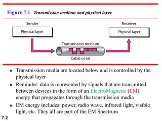
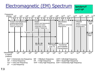
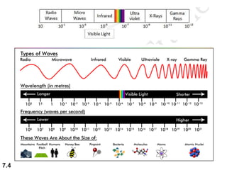
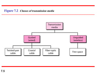
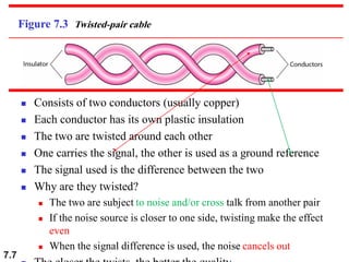
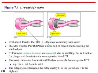
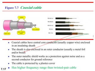
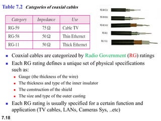
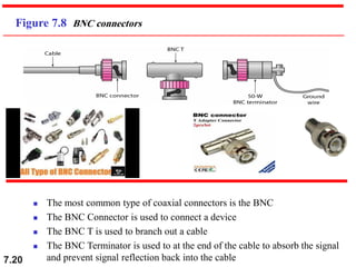
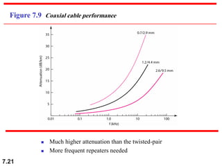
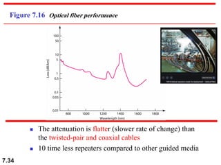
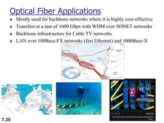
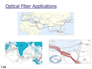
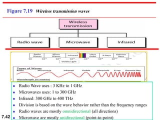
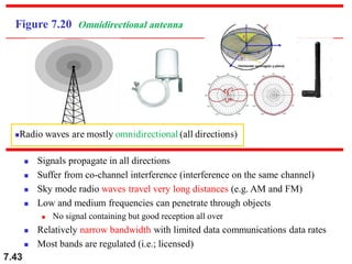
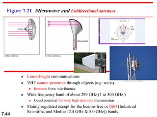
7.1
Chapter 7
Transmission Media
Copyright © The McGraw-Hill Companies, Inc. Permission required for reproduction or display.
7.2
Figure 7.1 Transmission medium and physical layer
◼ Transmission media are located below and is controlled by the
physical layer
◼ Reminder: data is represented by signals that are transmitted
between devices in the form of an ElectroMagnetic (EM)
energy that propagates through the transmission media
◼ EM energy includes: power, radio wave, infrared light, visible
light, etc. They all are part of the EM Spectrum
7.3
Electromagnetic (EM) Spectrum lamda=c/f
c=3*108
7.4
7.5
Figure 7.2 Classes of transmission media
7.6
7-1 GUIDED MEDIA
Guided media, which are those that provide a
conduit from one device to another, include twisted-
pair cable, coaxial cable, and fiber-optic cable.
Twisted-Pair Cable
Coaxial Cable
Fiber-Optic Cable
Topics discussed in this section:
7.7
Figure 7.3 Twisted-pair cable
◼ Consists of two conductors (usually copper)
◼ Each conductor has its own plastic insulation
◼ The two are twisted around each other
◼ One carries the signal, the other is used as a ground reference
◼ The signal used is the difference between the two
◼ Why are they twisted?
◼ The two are subject to noise and/or cross talk from another pair
◼ If the noise source is closer to one side, twisting make the effect
even
◼ When the signal difference is used, the noise cancels out
7.8
Figure 7.4 UTP and STP cables
◼ Unshielded Twisted Pair (UTP) is the most commonly used cable
◼ Shielded Twisted Pair (STP) has a metal foil or braded-mesh covering the
shielded pair
◼ STP is more immune to noise and cross talk due to shielding, but is it bulkier
(i.e.; larger and heavier) and more expensive than UTP
◼ Electronic Industries Association (EIA) has standards that categorize UTP
◼ e.g. Cat 4, cat 5, cat 6, cat 7
◼ The categories are based on the cable quality (1 is the lowest and 7 is the
highest)
7.9
7.10
7.11
reading
7.12
Table 7.1 Categories of unshielded twisted-pair cables
7.13
Figure 7.5 UTP connector
◼ The most common UTP connector is the RJ-45
(Registered Jack-45)
◼ RJ-45 is a keyed connector
◼ Commonly used for Ethernet connections
◼ Other types are RJ-11 (phone lines) and RJ-10 (phone
7.14
Figure 7.6 UTP performance ◼Gauge (the thickness of the wire)
7.15
Exercise fro you
7.16
UTP Applications
◼ Twisted-pair cables are widely used in telephone lines
◼ The local loop (the line that connects the subscriber to the
central office) is mostly a UTP
◼ Digital Subscriber Lines (DSL) used to provide high-speed
data connection utilizes the high bandwidth of the UTP
◼ Local Area Networks (LANs) such as 10Base-T and 100Base-
T use twisted-pair cables
7.17
Figure 7.7 Coaxial cable
◼ Coaxial cables have central core conductor (usually copper wire) enclosed
in an insulating sheath
◼ The sheath is also enclosed in an outer conductor (usually a metal foil
and/or braid)
◼ The outer metallic shield works as a protection against noise and as a
second conductor for ground reference
◼ The cable is protected by a plastics cover
◼ Has higher frequency range than twisted-pair cable
7.18
Table 7.2 Categories of coaxial cables
◼ Coaxial cables are categorized by Radio Government (RG) ratings
◼ Each RG rating defines a unique set of physical specifications
such as:
◼ Gauge (the thickness of the wire)
◼ The thickness and type of the inner insulator
◼ The construction of the shield
◼ The size and type of the outer casting
◼ Each RG rating is usually specified for a certain function and
application (TV cables, LANs, Cameras Sys, ..etc)
7.19
7.20
Figure 7.8 BNC connectors
◼ The most common type of coaxial connectors is the BNC
◼ The BNC Connector is used to connect a device
◼ The BNC T is used to branch out a cable
◼ The BNC Terminator is used to at the end of the cable to absorb the signal
and prevent signal reflection back into the cable
7.21
Figure 7.9 Coaxial cable performance
◼ Much higher attenuation than the twisted-pair
◼ More frequent repeaters needed
7.22
Coaxial Cable Applications
◼ Mostly replaced by fiber-optic cables
◼ Earlier used in:
◼ Analog telephone networks (10,000 voice signals per cable)
◼ Traditional cable TV networks for the infrastructure
◼ Traditional Ethernet LANs:
◼ 10Base-2 (Thin Ethernet) using RG-58 with BNC connector for 10
Mbps data rate for a range of 185 m
◼ 10Base-5 (Thick Ethernet) using RG-11 with specialized connectors
for 10 Mbps data rate over a range of 5,000 m
◼ Later used in:
◼ Digital telephone networks (600 Mbps per cable)
◼ Cable TV networks, where RG-59 is used to connect the
subscriber to the infrastructure (mostly fiber-optic now)
7.23
7.24
Fiber-Optic Cable
◼ Made of glass or plastic
◼ Transmits signals in the form of light
◼ Uses the light ray reflection and refraction
laws of physics for signal propagation
7.25
Figure 7.10 Bending of light ray
◼ Light travels in straight lines if traveling through a single uniform substance
◼ If the light moves from one substance to another with a different density, the
light changes its direction
◼ The angle of incidence is the angle the light makes with the line
perpendicular to the interface between the two substances
◼ The critical angle of incidence is the angle at which the light travels along
the interface between the two substances
◼ If the angle of incidence is greater than the critical, the light reflects back
◼ The critical angle is a property of the substance
7.26
https://www.google.com/search?q=how+light+travels+in+fiber&tbm=isch&ved=2a
hUKEwiy1OX_2M7oAhVFlRoKHV-ZAGAQ2-
cCegQIABAA&oq=how+light+travels+in+fiber&gs_lcp=CgNpbWcQAzoECCMQJzoECA
AQQzoCCAA6BAgAEB46BggAEAgQHjoECAAQEzoICAAQCBAeEBNQuaIdWObZHWCz3R1
oAHAAeACAAe8BiAHxH5IBBjAuMjEuNZgBAKABAaoBC2d3cy13aXotaW1n&sclient=img
&ei=NXOIXvLlN8Wqat-ygoAG&bih=608&biw=1039#imgrc=z_wxhPVufyx1OM
Click o
the link
7.27
Figure 7.11 Optical fiber
◼ Optical fibers use reflections to guide a light through a channel
◼ The glass or plastic core is surrounded by a cladding of less
dense glass or plastic such that the light is reflected at the
required angle of incidence
7.28
Figure 7.12 Propagation modes
7.29
Optical Fiber Modes
◼ Multimode: multiple beams move through the core in different paths
1. Step-Index fiber:
◼ The density of the core is constant (the index of refraction is fixed)
◼ The light moves is straight lines until it hits the cladding where it
reflects suddenly
2. Graded-Index fiber:
◼ The density of the core decreases as the light moves from the center to the
cladding
◼ The light changes in curved line and reflects smoothly off of the cladding
◼ The received signal is less distorted compared to the step-index
7.30
Optical Fiber Modes
◼ Single-Mode:
◼ Uses step-index fiber and highly focused light source with limited range of angles
◼ Smaller diameter and lower density fiber compared to multimode
◼ Therefore, critical angle ~90 degrees to force all beams to almost propagate
horizontally
◼ Propagation of different beams are almost identical with negligible delays
◼ The beams can be recombined with little distortion to the signal
7.31
Table 7.3 Fiber types
◼ Defined by the ratio of the core to the cladding
diameters usually expressed in micrometers
7.32
Figure 7.14 Fiber construction
◼ Outer jacket is made of PVC or Teflon
◼ Kelvar is used for bulletproof vests
7.33
Figure 7.15 Fiber-optic cable connectors
◼ SC (Subscriber Channel) is used for cable TV
◼ ST (Straight Tip) is used for connecting cables to networking devices
◼ MT-RJ is a new type of connector that is similar in size to the RJ-45
connector
7.34
Figure 7.16 Optical fiber performance
◼ The attenuation is flatter (slower rate of change) than
the twisted-pair and coaxial cables
◼ 10 time less repeaters compared to other guided media
7.35
Optical Fiber Applications
◼ Mostly used for backbone networks where it is highly cost-effective
◼ Transfers at a rate of 1600 Gbps with WDM over SONET networks
◼ Backbone infrastructure for Cable TV networks
◼ LAN over 100Base-FX networks (fast Ethernet) and 1000Base-X
7.36
Optical Fiber Applications
7.37
Advantages and Disadvantages of Optical Fiber
◼ Advantages:
1. High bandwidth: its bandwidth is limited by signal
generation and reception; not by the medium
2. Low attenuation: 50 Km spaced repeaters
3. No EM interference
4. No corrosion
5. Light weight
6. No tapping
◼ Disadvantages
◼ Installation/maintenance
◼ Unidirectional
◼ Expensive
7.38
7-2 UNGUIDED MEDIA: WIRELESS
Unguided media transport electromagnetic waves
without using a physical conductor. This type of
communication is often referred to as wireless
communication.
• Radio Waves
• Microwaves
• Infrared
Topics discussed in this section:
7.39
Figure 7.17 Electromagnetic spectrum for wireless communication
◼ Transporting EM waves without a physical conductor (wireless)
◼ Signals are transmitted (broadcasted) over the air
◼ Frequency range: 3 KHz to 900 THz
◼ Types of unguided signal propagations:
1. Ground
2. Sky
3. Line-of-sight (LOS)
7.40
Figure 7.18 Propagation methods
Ground
◼ Low frequency
◼ Travels in all
directions
◼ Follow curvature of
the earth
◼ Used navigation
systems
SKY
◼ Higher frequency
◼ Travels upward
◼ Reflects off of the
Ionosphere
◼ Greater distance with
lower power
◼ Used in: AM, FM, &
Line-of-Site
◼ Very high freq.
◼ Straight line
transmission
◼ Point-to-point
◼ High towers needed
◼ Used in: Radar &
Satellites & Cell
7.41
Table 7.4 Bands
7.42
Figure 7.19 Wireless transmission waves
◼ Radio Wave uses : 3 KHz to 1 GHz
◼ Microwaves uses: 1 to 300 GHz
◼ Infrared: 300 GHz to 400 THz
◼ Division is based on the wave behavior rather than the frequency ranges
◼ Radio waves are mostly omnidirectional (all directions)
◼ Microwave are mostly unidirectional (point-to-point)
7.43
Figure 7.20 Omnidirectional antenna
◼ Signals propagate in all directions
◼ Suffer from co-channel interference (interference on the same channel)
◼ Sky mode radio waves travel very long distances (e.g. AM and FM)
◼ Low and medium frequencies can penetrate through objects
◼ No signal containing but good reception all over
◼ Relatively narrow bandwidth with limited data communications data rates
◼ Most bands are regulated (i.e.; licensed)
7.44
Figure 7.21 Microwave and Unidirectional antennas
◼ Line-of-sight communications
◼ VHF cannot penetrate through objects (e.g. walls)
◼ Immune from interference
◼ Wide frequency band of about 299 GHz (1 to 300 GHz )
◼ Good potential for very high data rate transmission
◼ Mainly regulated except for the license-free or ISM (Industrial
Scientific, and Medical 2.4 GHz & 5.0 GHz)) bands
7.45
Microwaves are used for unicast
communication such as cellular
telephones, satellite networks,
and wireless LANs.
Note
7.46
Infrared
◼ 300 GHz to 400 THz
◼ Line-of-sight very short-range and very high data rate
communications
◼ Cannot penetrate through objects (e.g. walls)
◼ Immune from interference
◼ Use only for inside applications: such as remote control, PC
data transfer, etc.
◼ IrDA (Infrared Data Association)
◼ It is a Standard body for IR communications
◼ It Defines standards for communication between PC and
peripheral devices (e.g USB,
◼ Rate=75 kbps, range= up to 8 meters line-of-site
communications
7.47
7.48
Infrared signals can be used for short-
range communication in a closed area
using line-of-sight propagation.
Note

Computer Networks/Computer Engineering.pdf

  • 1.
    7.1 Chapter 7 Transmission Media Copyright© The McGraw-Hill Companies, Inc. Permission required for reproduction or display.
  • 2.
    7.2 Figure 7.1 Transmissionmedium and physical layer ◼ Transmission media are located below and is controlled by the physical layer ◼ Reminder: data is represented by signals that are transmitted between devices in the form of an ElectroMagnetic (EM) energy that propagates through the transmission media ◼ EM energy includes: power, radio wave, infrared light, visible light, etc. They all are part of the EM Spectrum
  • 3.
  • 4.
  • 5.
    7.5 Figure 7.2 Classesof transmission media
  • 6.
    7.6 7-1 GUIDED MEDIA Guidedmedia, which are those that provide a conduit from one device to another, include twisted- pair cable, coaxial cable, and fiber-optic cable. Twisted-Pair Cable Coaxial Cable Fiber-Optic Cable Topics discussed in this section:
  • 7.
    7.7 Figure 7.3 Twisted-paircable ◼ Consists of two conductors (usually copper) ◼ Each conductor has its own plastic insulation ◼ The two are twisted around each other ◼ One carries the signal, the other is used as a ground reference ◼ The signal used is the difference between the two ◼ Why are they twisted? ◼ The two are subject to noise and/or cross talk from another pair ◼ If the noise source is closer to one side, twisting make the effect even ◼ When the signal difference is used, the noise cancels out
  • 8.
    7.8 Figure 7.4 UTPand STP cables ◼ Unshielded Twisted Pair (UTP) is the most commonly used cable ◼ Shielded Twisted Pair (STP) has a metal foil or braded-mesh covering the shielded pair ◼ STP is more immune to noise and cross talk due to shielding, but is it bulkier (i.e.; larger and heavier) and more expensive than UTP ◼ Electronic Industries Association (EIA) has standards that categorize UTP ◼ e.g. Cat 4, cat 5, cat 6, cat 7 ◼ The categories are based on the cable quality (1 is the lowest and 7 is the highest)
  • 9.
  • 10.
  • 11.
  • 12.
    7.12 Table 7.1 Categoriesof unshielded twisted-pair cables
  • 13.
    7.13 Figure 7.5 UTPconnector ◼ The most common UTP connector is the RJ-45 (Registered Jack-45) ◼ RJ-45 is a keyed connector ◼ Commonly used for Ethernet connections ◼ Other types are RJ-11 (phone lines) and RJ-10 (phone
  • 14.
    7.14 Figure 7.6 UTPperformance ◼Gauge (the thickness of the wire)
  • 15.
  • 16.
    7.16 UTP Applications ◼ Twisted-paircables are widely used in telephone lines ◼ The local loop (the line that connects the subscriber to the central office) is mostly a UTP ◼ Digital Subscriber Lines (DSL) used to provide high-speed data connection utilizes the high bandwidth of the UTP ◼ Local Area Networks (LANs) such as 10Base-T and 100Base- T use twisted-pair cables
  • 17.
    7.17 Figure 7.7 Coaxialcable ◼ Coaxial cables have central core conductor (usually copper wire) enclosed in an insulating sheath ◼ The sheath is also enclosed in an outer conductor (usually a metal foil and/or braid) ◼ The outer metallic shield works as a protection against noise and as a second conductor for ground reference ◼ The cable is protected by a plastics cover ◼ Has higher frequency range than twisted-pair cable
  • 18.
    7.18 Table 7.2 Categoriesof coaxial cables ◼ Coaxial cables are categorized by Radio Government (RG) ratings ◼ Each RG rating defines a unique set of physical specifications such as: ◼ Gauge (the thickness of the wire) ◼ The thickness and type of the inner insulator ◼ The construction of the shield ◼ The size and type of the outer casting ◼ Each RG rating is usually specified for a certain function and application (TV cables, LANs, Cameras Sys, ..etc)
  • 19.
  • 20.
    7.20 Figure 7.8 BNCconnectors ◼ The most common type of coaxial connectors is the BNC ◼ The BNC Connector is used to connect a device ◼ The BNC T is used to branch out a cable ◼ The BNC Terminator is used to at the end of the cable to absorb the signal and prevent signal reflection back into the cable
  • 21.
    7.21 Figure 7.9 Coaxialcable performance ◼ Much higher attenuation than the twisted-pair ◼ More frequent repeaters needed
  • 22.
    7.22 Coaxial Cable Applications ◼Mostly replaced by fiber-optic cables ◼ Earlier used in: ◼ Analog telephone networks (10,000 voice signals per cable) ◼ Traditional cable TV networks for the infrastructure ◼ Traditional Ethernet LANs: ◼ 10Base-2 (Thin Ethernet) using RG-58 with BNC connector for 10 Mbps data rate for a range of 185 m ◼ 10Base-5 (Thick Ethernet) using RG-11 with specialized connectors for 10 Mbps data rate over a range of 5,000 m ◼ Later used in: ◼ Digital telephone networks (600 Mbps per cable) ◼ Cable TV networks, where RG-59 is used to connect the subscriber to the infrastructure (mostly fiber-optic now)
  • 23.
  • 24.
    7.24 Fiber-Optic Cable ◼ Madeof glass or plastic ◼ Transmits signals in the form of light ◼ Uses the light ray reflection and refraction laws of physics for signal propagation
  • 25.
    7.25 Figure 7.10 Bendingof light ray ◼ Light travels in straight lines if traveling through a single uniform substance ◼ If the light moves from one substance to another with a different density, the light changes its direction ◼ The angle of incidence is the angle the light makes with the line perpendicular to the interface between the two substances ◼ The critical angle of incidence is the angle at which the light travels along the interface between the two substances ◼ If the angle of incidence is greater than the critical, the light reflects back ◼ The critical angle is a property of the substance
  • 26.
  • 27.
    7.27 Figure 7.11 Opticalfiber ◼ Optical fibers use reflections to guide a light through a channel ◼ The glass or plastic core is surrounded by a cladding of less dense glass or plastic such that the light is reflected at the required angle of incidence
  • 28.
  • 29.
    7.29 Optical Fiber Modes ◼Multimode: multiple beams move through the core in different paths 1. Step-Index fiber: ◼ The density of the core is constant (the index of refraction is fixed) ◼ The light moves is straight lines until it hits the cladding where it reflects suddenly 2. Graded-Index fiber: ◼ The density of the core decreases as the light moves from the center to the cladding ◼ The light changes in curved line and reflects smoothly off of the cladding ◼ The received signal is less distorted compared to the step-index
  • 30.
    7.30 Optical Fiber Modes ◼Single-Mode: ◼ Uses step-index fiber and highly focused light source with limited range of angles ◼ Smaller diameter and lower density fiber compared to multimode ◼ Therefore, critical angle ~90 degrees to force all beams to almost propagate horizontally ◼ Propagation of different beams are almost identical with negligible delays ◼ The beams can be recombined with little distortion to the signal
  • 31.
    7.31 Table 7.3 Fibertypes ◼ Defined by the ratio of the core to the cladding diameters usually expressed in micrometers
  • 32.
    7.32 Figure 7.14 Fiberconstruction ◼ Outer jacket is made of PVC or Teflon ◼ Kelvar is used for bulletproof vests
  • 33.
    7.33 Figure 7.15 Fiber-opticcable connectors ◼ SC (Subscriber Channel) is used for cable TV ◼ ST (Straight Tip) is used for connecting cables to networking devices ◼ MT-RJ is a new type of connector that is similar in size to the RJ-45 connector
  • 34.
    7.34 Figure 7.16 Opticalfiber performance ◼ The attenuation is flatter (slower rate of change) than the twisted-pair and coaxial cables ◼ 10 time less repeaters compared to other guided media
  • 35.
    7.35 Optical Fiber Applications ◼Mostly used for backbone networks where it is highly cost-effective ◼ Transfers at a rate of 1600 Gbps with WDM over SONET networks ◼ Backbone infrastructure for Cable TV networks ◼ LAN over 100Base-FX networks (fast Ethernet) and 1000Base-X
  • 36.
  • 37.
    7.37 Advantages and Disadvantagesof Optical Fiber ◼ Advantages: 1. High bandwidth: its bandwidth is limited by signal generation and reception; not by the medium 2. Low attenuation: 50 Km spaced repeaters 3. No EM interference 4. No corrosion 5. Light weight 6. No tapping ◼ Disadvantages ◼ Installation/maintenance ◼ Unidirectional ◼ Expensive
  • 38.
    7.38 7-2 UNGUIDED MEDIA:WIRELESS Unguided media transport electromagnetic waves without using a physical conductor. This type of communication is often referred to as wireless communication. • Radio Waves • Microwaves • Infrared Topics discussed in this section:
  • 39.
    7.39 Figure 7.17 Electromagneticspectrum for wireless communication ◼ Transporting EM waves without a physical conductor (wireless) ◼ Signals are transmitted (broadcasted) over the air ◼ Frequency range: 3 KHz to 900 THz ◼ Types of unguided signal propagations: 1. Ground 2. Sky 3. Line-of-sight (LOS)
  • 40.
    7.40 Figure 7.18 Propagationmethods Ground ◼ Low frequency ◼ Travels in all directions ◼ Follow curvature of the earth ◼ Used navigation systems SKY ◼ Higher frequency ◼ Travels upward ◼ Reflects off of the Ionosphere ◼ Greater distance with lower power ◼ Used in: AM, FM, & Line-of-Site ◼ Very high freq. ◼ Straight line transmission ◼ Point-to-point ◼ High towers needed ◼ Used in: Radar & Satellites & Cell
  • 41.
  • 42.
    7.42 Figure 7.19 Wirelesstransmission waves ◼ Radio Wave uses : 3 KHz to 1 GHz ◼ Microwaves uses: 1 to 300 GHz ◼ Infrared: 300 GHz to 400 THz ◼ Division is based on the wave behavior rather than the frequency ranges ◼ Radio waves are mostly omnidirectional (all directions) ◼ Microwave are mostly unidirectional (point-to-point)
  • 43.
    7.43 Figure 7.20 Omnidirectionalantenna ◼ Signals propagate in all directions ◼ Suffer from co-channel interference (interference on the same channel) ◼ Sky mode radio waves travel very long distances (e.g. AM and FM) ◼ Low and medium frequencies can penetrate through objects ◼ No signal containing but good reception all over ◼ Relatively narrow bandwidth with limited data communications data rates ◼ Most bands are regulated (i.e.; licensed)
  • 44.
    7.44 Figure 7.21 Microwaveand Unidirectional antennas ◼ Line-of-sight communications ◼ VHF cannot penetrate through objects (e.g. walls) ◼ Immune from interference ◼ Wide frequency band of about 299 GHz (1 to 300 GHz ) ◼ Good potential for very high data rate transmission ◼ Mainly regulated except for the license-free or ISM (Industrial Scientific, and Medical 2.4 GHz & 5.0 GHz)) bands
  • 45.
    7.45 Microwaves are usedfor unicast communication such as cellular telephones, satellite networks, and wireless LANs. Note
  • 46.
    7.46 Infrared ◼ 300 GHzto 400 THz ◼ Line-of-sight very short-range and very high data rate communications ◼ Cannot penetrate through objects (e.g. walls) ◼ Immune from interference ◼ Use only for inside applications: such as remote control, PC data transfer, etc. ◼ IrDA (Infrared Data Association) ◼ It is a Standard body for IR communications ◼ It Defines standards for communication between PC and peripheral devices (e.g USB, ◼ Rate=75 kbps, range= up to 8 meters line-of-site communications
  • 47.
  • 48.
    7.48 Infrared signals canbe used for short- range communication in a closed area using line-of-sight propagation. Note