Download as PDF, PPTX

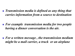
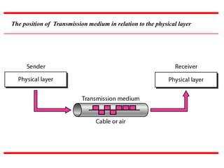
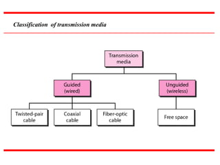

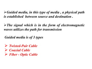
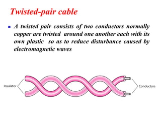

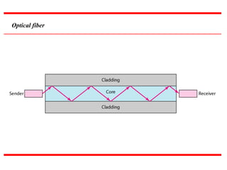
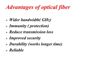
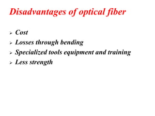
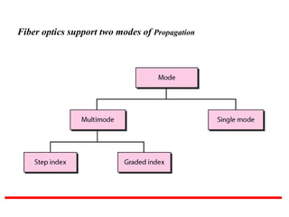
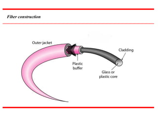
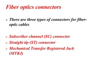
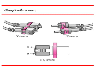

The document provides an overview of various types of transmission media, including guided and unguided media, elaborating on twisted-pair cables, coaxial cables, and fiber optics with their respective advantages and disadvantages. It explains the functions and characteristics of each type of media, alongside connector types and classification standards. Additionally, it covers unguided media, including radio waves, microwaves, and infrared communication methods.