Downloaded 173 times

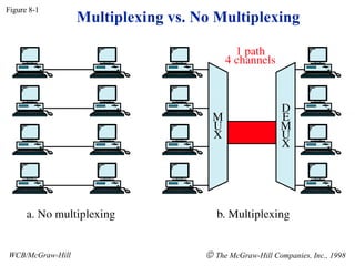
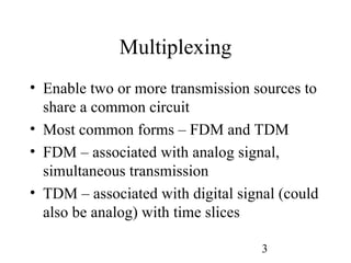
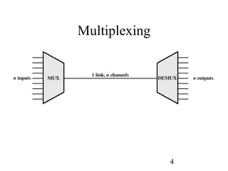
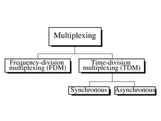
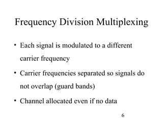
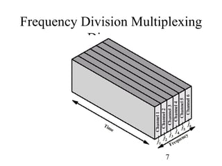
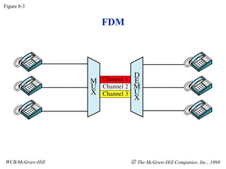
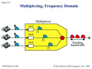
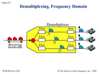
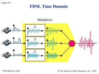
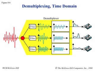
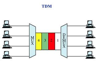
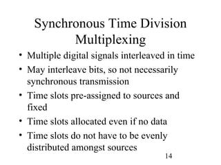
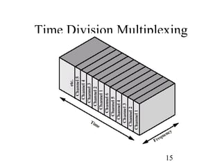
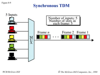
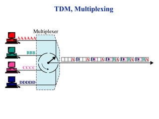
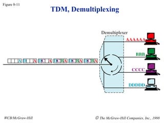
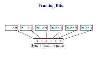
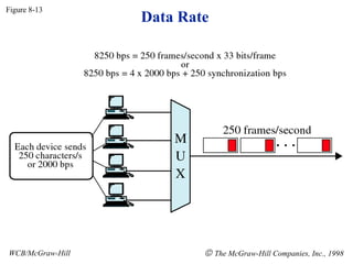
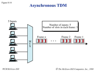
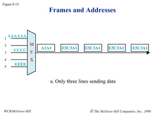
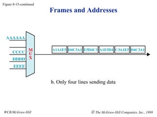
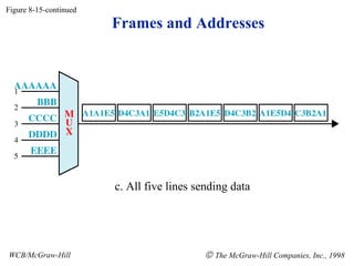
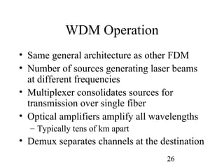
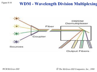
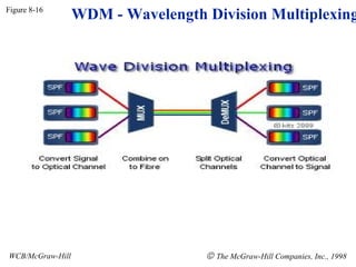
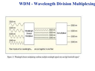

Multiplexing techniques such as frequency division multiplexing (FDM), time division multiplexing (TDM), and wavelength division multiplexing (WDM) allow multiple transmission sources to share a common circuit. FDM involves modulating each signal to a different carrier frequency with guard bands between frequencies. TDM involves interleaving digital signals in time slots, which may be allocated even if no data is being sent. WDM transmits multiple beams of light at different wavelengths over an optical fiber, functioning as a form of FDM for optical networks.