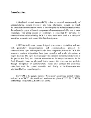
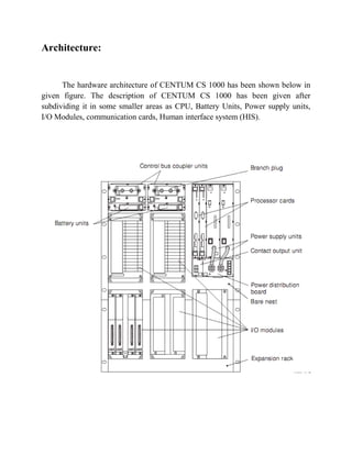
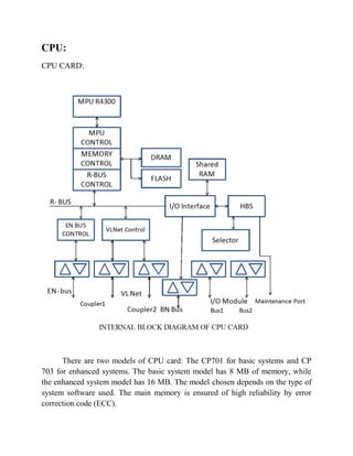
SlideShare a Scribd company logo
Distributed Control System (DCS)
CONTENTS:
1)Introduction
2)Architecture
3)CPU
4)Analog Input Module
5)Digital Input Module
6)Analog Output Module
7)Digital Output Module
8)Communication System
9)Human Interface system (HIS)
10) Applications
Introduction:
A distributed control system (DCS) refers to a control system usually of
a manufacturing system, process or any kind of dynamic system, in which
the controller elements are not central in location (like the brain) but are distributed
throughout the system with each component sub-system controlled by one or more
controllers. The entire system of controllers is connected by networks for
communication and monitoring. DCS is a very broad term used in a variety of
industries, to monitor and control distributed equipment.
A DCS typically uses custom designed processors as controllers and uses
both proprietary interconnections and communications protocol for
communication. Input and output modules form component parts of the DCS. The
processor receives information from input modules and sends information to
output modules. The input modules receive information from input instruments in
the process (or field) and transmit instructions to the output instruments in the
field. Computer buses or electrical buses connect the processor and modules
through multiplexer or demultiplexers. Buses also connect the distributed
controllers with the central controller and finally to the Human–machine
interface (HMI) or control consoles.
CENTUM is the generic name of Yokogawa’s distributed control systems
(referred to as “DCS” ) for small- and medium-scale plants (CENTUM CS 1000),
and for large scale plants (CENTUM CS 3000).
Architecture:
The hardware architecture of CENTUM CS 1000 has been shown below in
given figure. The description of CENTUM CS 1000 has been given after
subdividing it in some smaller areas as CPU, Battery Units, Power supply units,
I/O Modules, communication cards, Human interface system (HIS).
CPU:
CPU CARD:
There are two models of CPU card: The CP701 for basic systems and CP
703 for enhanced systems. The basic system model has 8 MB of memory, while
the enhanced system model has 16 MB. The model chosen depends on the type of
system software used. The main memory is ensured of high reliability by error
correction code (ECC).
The redundancy architecture of the CPU is referred to as a synchronous hot
standby system, which is the fundamentally the same as that of the CENTUM CS,
the only difference being the addition of the new error detection and protection
functions. These functions set write protected areas in each CPU card to protect the
program and database areas against illegal address writing instruction from the
other CPU card, and thereby prevents both card from failing due to illegal accesses
caused by malfunctions in MPU. Other newly added functions include the memory
management unit (MMU) and write protection which ensure data integrity, the
parity check of addresses and data, the ECC memory, and a two wire signal self
checker.
Power Supply Card:
The power supply card is designed to supply power to the common nests,
such as the CPU cards, and up to five I/O module nests. Standardizing the output
voltages to +5 V DC has simplified the circuit and structure and reduced the
number of parts. This allowed a power-factor Improvement unit to be built in so as
to comply with the aforementioned EN61000-3-2, class A standard (relating to
power line harmonics). The +5V DC outputs from the two power supply cards pass
through diodes so that they can be coupled externally for redundancy purposes.
The input-voltage monitoring signal (AC ready) and output-voltage
monitoring signal (DC ready) together with the guaranteed retention time of the
+5V DC output, enable to control to continue over a temporary power failure. The
output voltage retention time immediately after a power failure is clearly defined in
the specifications since it is closely related to the software saving process in the
CPU card.
Nest Configuration:
The FCS nest is composed of VL Net couplers, battery units for backing up
the CPUs’ main memory, a backboard, a power distribution board, and a ready
signal output unit in addition to the CPU cards and power supply card. A FCS
model has five I/O modules nest.
Input & Output Modules:
The I/O modules convert the analog or digital signals from the field
equipment then pass to field control stations or vice versa to convert the signals
from the field control station to the signals for the field equipment. The I/O module
can be categorized into the following seven main types-
• Analog I/O module
• Multipoint control analog I/O module
• Relay I/O module
• Multiplexer module
• Digital I/O module
• Communication module
• Communication card
Analog Input Module:
List of I/O Modules Installable in Analog I/O Module Nest:
Types Model Name
Analog I/O Module
AAM10 Current/voltage input module
(Simplified type)
AAM11 Current/voltage input module
AAM11B Current/voltage input module
(supports BRAIN)
AAM21 mV, thermocouple, RTD
input module
AAM21J mV, thermocouple, RTD
input module
APM11 Pulse input module
AAM50 Current output module
AAM51 Current/voltage output module
Wiring of Analog I/O Module:
Models AAM10, AAM11, AAM11B, AAM21, AAM21J, APM11, AAM50,
AAM51
If output signal between 1 - 5V DC needs to be output to a recorder, etc.,
connect the Model AKB301 cable to the (CN1) connector. For example, to output
signal from the terminal block TE16 to the recorder, connect cable Model AKB301
between CN1 and the terminal block.
Digital I/O Module:
The digital I/O module is configured by the card unit and either the terminal
unit or connector unit. It inputs and outputs 16 or 32 signal points and converts
signals. Since the types or I/O signals are software-set, no control switch or knob is
found on this module.
The table below shows the types of digital I/O modules.
Types Models
Terminal
Unit/Connector Unit/
Card Unit Names (*1)
Digital I/O Module
Names
Terminal type
ADM11T
ADT16 (terminal)
ADM11 (card)
Contact input module
(16-point, terminal
type)
ADM12T
ADT32 (terminal)
ADM12 (card)
Contact input module
(32-point, terminal
type)
ADM51T
ADT16 (terminal)
ADM51 (card)
Contact output
module (16-point,
terminal type)
ADM52T
ADT32 (terminal)
ADM52 (card)
Contact output
module (32-point,
terminal type)
Connector
type
ADM11C
ADC16
(connector)
ADM11 (card)
Contact input module
(16-point, connector
type)
ADM12C
ADC32 (connector
ADM12 (card)
Contact input module
(32-point, connector
type)
ADM51C
ADC16 (connector
ADM51 (card)
Contact output
module (16-point,
connector type)
ADM52C
ADC32
(connector)
ADM52 (card)
Contact output
module (32-point,
connector type)
Wiring of Digital I/O Module (Connector Type):
Digital I/O module (connector type)
Models ADM11C, ADM12C, ADM51C, ADM52C
Communication Cards:
The communication cards are used to realize the general-purpose
communication of field control station and subsystems via serial links, so that the
subsystem may be controlled or monitored.
Different from the above mentioned cards, the communication package with
subsystems is prepared for ACM21 and ACM22 so that the general-purpose
communication may be conveniently realized. The ACM71 Ethernet
communication module receives/sends data from/to subsystems such as MELSEC
via Ethernet.
Communication card models:
ACM21: RS-232C communication card
ACM22: RS-422/RS-485 communication card
ACM71: Ethernet communication module
HIS Operation And Monitoring Windows:
There are different operational and monitoring windows, which have to define
during designing Human Interface Station (HIS).The different windows are shown
below:
1) Basic Windows for Operation and Monitoring
1. System Message Window
2. Navigator Window
2) Windows Convenient for Operation and Monitoring
1. Graphic Window
2. Trend Window
3. Tuning Window
4. Faceplate Window
5. Operator Guide Window
6. Process Alarm Window
7. Message Monitor Window
8. SFC Window
9. Logic Chart Window
10.Sequence Table Window
11.Control Drawing Window
12.Help Dialog Box
3) Windows for Batch Operation and Monitoring
4) Windows for Process Status and Operation Record Configuration
1. Process Report Window
2. Historical Message Report Window
5) Windows for System Administration
How the HIS looks like:
The human interface system programmed for a project/plan is designed in
such a way that it would be easy for the operator to understand all the operations
occurred in the plant. The example of visualization of a reactor control power plant
has been given below:
Example2:
Substation Automation: Visualization of typical substation comprising two
incomers and four feeders.
How the faceplate looks like:
Faceplate window is a type of window, where the process variation, switch
status has been displayed.
Applications:
A typical DCS consists of functionally and/or geographically distributed
digital controllers capable of executing from 1 to 256 or more regulatory control
loops in one control box. The input/output devices (I/O) can be integral with the
controller or located remotely via a field network. Today’s controllers have
extensive computational capabilities and, in addition to proportional, integral, and
derivative (PID) control, can generally perform logic and sequential control.
Modern DCSs also support neural networks and fuzzy application.
DCSs may employ one or more workstations and can be configured at the
workstation or by an off-line personal computer. Local communication is handled
by a control network with transmission over twisted pair, coaxial, or fiber optic
cable. A server and/or applications processor may be included in the system for
extra computational, data collection, and reporting capability.
Distributed control systems (DCSs) are dedicated systems used to control
manufacturing processes that are continuous or batch-oriented, such as –
1) Electrical power grids and electrical generation plants
2) Environmental control systems
3) Traffic signals
4) Radio signals
5) Water management systems
6) Oil refining plants
7) Metallurgical process plants
8) Chemical plants
9) Pharmaceutical manufacturing
10) Sensor networks
11) Dry cargo and bulk oil carrier ships etc.
Conclusion:
The development of CENTUM CS 1000 was accomplished in a short period
of time by using the parts and technologies field proven in CENTUM CS system
wherever possible. It is a low end model in the CENTUM CS series and is acting
as a key product for the global market taking over from the microXL system. The
CENTUM series hardware has identical architecture for plants of all scales. The
CENTUM CS 1000 has been assessed and updated so as to meet the ever
increasing market needs.

More Related Content

What's hot

What's hot (20)

Presentation on pneumatic actuator
Presentation on pneumatic actuatorPresentation on pneumatic actuator
Presentation on pneumatic actuator
 
Distributed Control System Basics
Distributed Control System BasicsDistributed Control System Basics
Distributed Control System Basics
 
Control valve positioners
Control valve positionersControl valve positioners
Control valve positioners
 
Modern Control - Lec 02 - Mathematical Modeling of Systems
Modern Control - Lec 02 - Mathematical Modeling of SystemsModern Control - Lec 02 - Mathematical Modeling of Systems
Modern Control - Lec 02 - Mathematical Modeling of Systems
 
PLC Basic
PLC BasicPLC Basic
PLC Basic
 
Pneumatic control valve
Pneumatic control valvePneumatic control valve
Pneumatic control valve
 
Instrumentation and process control fundamentals
Instrumentation and  process control fundamentalsInstrumentation and  process control fundamentals
Instrumentation and process control fundamentals
 
Plc example presentation
Plc example presentationPlc example presentation
Plc example presentation
 
Actuators
ActuatorsActuators
Actuators
 
Plc basics
Plc   basicsPlc   basics
Plc basics
 
Distributed Control System
Distributed Control SystemDistributed Control System
Distributed Control System
 
PLC Architecture
PLC ArchitecturePLC Architecture
PLC Architecture
 
Inst. & process control gtp
Inst. & process control gtpInst. & process control gtp
Inst. & process control gtp
 
Control Valves
Control ValvesControl Valves
Control Valves
 
SCADA PPT.pdf
SCADA PPT.pdfSCADA PPT.pdf
SCADA PPT.pdf
 
Dcs
DcsDcs
Dcs
 
pid controller
 pid controller pid controller
pid controller
 
Pneumatic 1
Pneumatic 1Pneumatic 1
Pneumatic 1
 
Controllers ppt
Controllers pptControllers ppt
Controllers ppt
 
Plc presentation
Plc presentation Plc presentation
Plc presentation
 

Viewers also liked

DCS PRESENTATION
DCS PRESENTATIONDCS PRESENTATION
DCS PRESENTATIONbvent2005
 
Migrating Bailey Consoles R1
Migrating Bailey Consoles R1Migrating Bailey Consoles R1
Migrating Bailey Consoles R1Alvaro Rendon
 
7. advantages of digital system
7. advantages of digital system7. advantages of digital system
7. advantages of digital systemSajjad Mehmood
 
Four keys to securing distributed control systems and the industrial (IoT)
Four keys to securing distributed control systems and the industrial (IoT)Four keys to securing distributed control systems and the industrial (IoT)
Four keys to securing distributed control systems and the industrial (IoT)Real-Time Innovations (RTI)
 
Ch1.number systems
Ch1.number systemsCh1.number systems
Ch1.number systemsteba
 
Digital and Logic Design Chapter 1 binary_systems
Digital and Logic Design Chapter 1 binary_systemsDigital and Logic Design Chapter 1 binary_systems
Digital and Logic Design Chapter 1 binary_systemsImran Waris
 
Digital logic gates
Digital logic gatesDigital logic gates
Digital logic gatesjsearle11
 
Digital logic gate and its application
Digital logic gate and its applicationDigital logic gate and its application
Digital logic gate and its applicationAbdullah Al Masud
 
faults in digital systems
faults in digital systemsfaults in digital systems
faults in digital systemsdennis gookyi
 
Digital Logic & Design (DLD) presentation
Digital Logic & Design (DLD) presentationDigital Logic & Design (DLD) presentation
Digital Logic & Design (DLD) presentationfoyez ahammad
 
Chapter 1 digital systems and binary numbers
Chapter 1 digital systems and binary numbersChapter 1 digital systems and binary numbers
Chapter 1 digital systems and binary numbersMohammad Bashartullah
 
digital control Chapter1 slide
digital control Chapter1 slidedigital control Chapter1 slide
digital control Chapter1 slideasyrafjpk
 
digital logic design number system
digital logic design number systemdigital logic design number system
digital logic design number systemNallapati Anindra
 
Mrs. Noland's Binary System ppt
Mrs. Noland's Binary System pptMrs. Noland's Binary System ppt
Mrs. Noland's Binary System pptdsparone
 

Viewers also liked (20)

DCS PRESENTATION
DCS PRESENTATIONDCS PRESENTATION
DCS PRESENTATION
 
DCS
DCSDCS
DCS
 
Distributed Control System
Distributed Control SystemDistributed Control System
Distributed Control System
 
Migrating Bailey Consoles R1
Migrating Bailey Consoles R1Migrating Bailey Consoles R1
Migrating Bailey Consoles R1
 
7. advantages of digital system
7. advantages of digital system7. advantages of digital system
7. advantages of digital system
 
Four keys to securing distributed control systems and the industrial (IoT)
Four keys to securing distributed control systems and the industrial (IoT)Four keys to securing distributed control systems and the industrial (IoT)
Four keys to securing distributed control systems and the industrial (IoT)
 
Semestrario tic
Semestrario ticSemestrario tic
Semestrario tic
 
Why SIL3 (ENG)
Why SIL3 (ENG)Why SIL3 (ENG)
Why SIL3 (ENG)
 
Ch1.number systems
Ch1.number systemsCh1.number systems
Ch1.number systems
 
Digital and Logic Design Chapter 1 binary_systems
Digital and Logic Design Chapter 1 binary_systemsDigital and Logic Design Chapter 1 binary_systems
Digital and Logic Design Chapter 1 binary_systems
 
Digital logic gates
Digital logic gatesDigital logic gates
Digital logic gates
 
Digital logic gate and its application
Digital logic gate and its applicationDigital logic gate and its application
Digital logic gate and its application
 
faults in digital systems
faults in digital systemsfaults in digital systems
faults in digital systems
 
Introduction to digital system
Introduction to digital systemIntroduction to digital system
Introduction to digital system
 
Digital Logic & Design (DLD) presentation
Digital Logic & Design (DLD) presentationDigital Logic & Design (DLD) presentation
Digital Logic & Design (DLD) presentation
 
Chapter 1 digital systems and binary numbers
Chapter 1 digital systems and binary numbersChapter 1 digital systems and binary numbers
Chapter 1 digital systems and binary numbers
 
digital control Chapter1 slide
digital control Chapter1 slidedigital control Chapter1 slide
digital control Chapter1 slide
 
digital logic design number system
digital logic design number systemdigital logic design number system
digital logic design number system
 
Chapter 8 - Main Memory
Chapter 8 - Main MemoryChapter 8 - Main Memory
Chapter 8 - Main Memory
 
Mrs. Noland's Binary System ppt
Mrs. Noland's Binary System pptMrs. Noland's Binary System ppt
Mrs. Noland's Binary System ppt
 

Similar to DCS ( Distributed Control System )

IMPLEMENTATION OF USER INTERFACE FOR MICROPROCESSOR TRAINER
IMPLEMENTATION OF USER INTERFACE FOR MICROPROCESSOR TRAINER IMPLEMENTATION OF USER INTERFACE FOR MICROPROCESSOR TRAINER
IMPLEMENTATION OF USER INTERFACE FOR MICROPROCESSOR TRAINER cscpconf
 
PLC, DCS and PLC vs DCS Presentation by Jitender Singh Shekhawat
PLC, DCS and PLC vs DCS Presentation by Jitender Singh ShekhawatPLC, DCS and PLC vs DCS Presentation by Jitender Singh Shekhawat
PLC, DCS and PLC vs DCS Presentation by Jitender Singh ShekhawatJitender Singh Shekhawat
 
Module 5 embedded systems,8051
Module 5 embedded systems,8051Module 5 embedded systems,8051
Module 5 embedded systems,8051Deepak John
 
Microcontoller and Embedded System
Microcontoller and Embedded SystemMicrocontoller and Embedded System
Microcontoller and Embedded SystemKaran Thakkar
 
Embedded systems class notes
Embedded systems  class notes Embedded systems  class notes
Embedded systems class notes Dr.YNM
 
CENTUM CS 3000 R3.pptx
CENTUM CS 3000 R3.pptxCENTUM CS 3000 R3.pptx
CENTUM CS 3000 R3.pptxEngrSaeedKhan2
 
Use of plc in industrial automation
Use of plc in industrial automationUse of plc in industrial automation
Use of plc in industrial automationAloka Patro
 
Project Report On Micro-controller Embedded System
Project Report On Micro-controller Embedded SystemProject Report On Micro-controller Embedded System
Project Report On Micro-controller Embedded SystemRkrishna Mishra
 
Embedded systems presentation
Embedded systems presentationEmbedded systems presentation
Embedded systems presentationSurender Singh
 
Lecture 10.cont,11 (plc)
Lecture 10.cont,11 (plc)Lecture 10.cont,11 (plc)
Lecture 10.cont,11 (plc)Mohamed Atef
 
Siemens Automation Station Compact Model PXC52
Siemens Automation Station Compact Model PXC52Siemens Automation Station Compact Model PXC52
Siemens Automation Station Compact Model PXC52CONTROLS & SYSTEMS
 
Gesture based vehicle movements control and alerting system docu
Gesture based vehicle movements control and alerting system docuGesture based vehicle movements control and alerting system docu
Gesture based vehicle movements control and alerting system docuVignan Munna
 
Low cost embedded system
Low cost embedded systemLow cost embedded system
Low cost embedded systemece svit
 

Similar to DCS ( Distributed Control System ) (20)

IMPLEMENTATION OF USER INTERFACE FOR MICROPROCESSOR TRAINER
IMPLEMENTATION OF USER INTERFACE FOR MICROPROCESSOR TRAINER IMPLEMENTATION OF USER INTERFACE FOR MICROPROCESSOR TRAINER
IMPLEMENTATION OF USER INTERFACE FOR MICROPROCESSOR TRAINER
 
PLC, DCS and PLC vs DCS Presentation by Jitender Singh Shekhawat
PLC, DCS and PLC vs DCS Presentation by Jitender Singh ShekhawatPLC, DCS and PLC vs DCS Presentation by Jitender Singh Shekhawat
PLC, DCS and PLC vs DCS Presentation by Jitender Singh Shekhawat
 
Module 5 embedded systems,8051
Module 5 embedded systems,8051Module 5 embedded systems,8051
Module 5 embedded systems,8051
 
Ajal 3
Ajal 3Ajal 3
Ajal 3
 
Microcontoller and Embedded System
Microcontoller and Embedded SystemMicrocontoller and Embedded System
Microcontoller and Embedded System
 
Embedded systems class notes
Embedded systems  class notes Embedded systems  class notes
Embedded systems class notes
 
CENTUM CS 3000 R3.pptx
CENTUM CS 3000 R3.pptxCENTUM CS 3000 R3.pptx
CENTUM CS 3000 R3.pptx
 
Use of plc in industrial automation
Use of plc in industrial automationUse of plc in industrial automation
Use of plc in industrial automation
 
Project Report On Micro-controller Embedded System
Project Report On Micro-controller Embedded SystemProject Report On Micro-controller Embedded System
Project Report On Micro-controller Embedded System
 
Vinod ppt on es31 08 15
Vinod ppt on es31 08 15Vinod ppt on es31 08 15
Vinod ppt on es31 08 15
 
Embedded systems presentation
Embedded systems presentationEmbedded systems presentation
Embedded systems presentation
 
Lecture 10.cont,11 (plc)
Lecture 10.cont,11 (plc)Lecture 10.cont,11 (plc)
Lecture 10.cont,11 (plc)
 
Siemens Automation Station Compact Model PXC52
Siemens Automation Station Compact Model PXC52Siemens Automation Station Compact Model PXC52
Siemens Automation Station Compact Model PXC52
 
Unit 5 Use of PLC.pptx
Unit 5 Use of PLC.pptxUnit 5 Use of PLC.pptx
Unit 5 Use of PLC.pptx
 
Gesture based vehicle movements control and alerting system docu
Gesture based vehicle movements control and alerting system docuGesture based vehicle movements control and alerting system docu
Gesture based vehicle movements control and alerting system docu
 
G05134851
G05134851G05134851
G05134851
 
Low cost embedded system
Low cost embedded systemLow cost embedded system
Low cost embedded system
 
Plc notes
Plc notesPlc notes
Plc notes
 
Embedded system
Embedded systemEmbedded system
Embedded system
 
Embeddedsystem
EmbeddedsystemEmbeddedsystem
Embeddedsystem
 

Recently uploaded

2024 DevOps Pro Europe - Growing at the edge
2024 DevOps Pro Europe - Growing at the edge2024 DevOps Pro Europe - Growing at the edge
2024 DevOps Pro Europe - Growing at the edgePaco Orozco
 
Quality defects in TMT Bars, Possible causes and Potential Solutions.
Quality defects in TMT Bars, Possible causes and Potential Solutions.Quality defects in TMT Bars, Possible causes and Potential Solutions.
Quality defects in TMT Bars, Possible causes and Potential Solutions.PrashantGoswami42
 
A case study of cinema management system project report..pdf
A case study of cinema management system project report..pdfA case study of cinema management system project report..pdf
A case study of cinema management system project report..pdfKamal Acharya
 
WATER CRISIS and its solutions-pptx 1234
WATER CRISIS and its solutions-pptx 1234WATER CRISIS and its solutions-pptx 1234
WATER CRISIS and its solutions-pptx 1234AafreenAbuthahir2
 
KIT-601 Lecture Notes-UNIT-4.pdf Frequent Itemsets and Clustering
KIT-601 Lecture Notes-UNIT-4.pdf Frequent Itemsets and ClusteringKIT-601 Lecture Notes-UNIT-4.pdf Frequent Itemsets and Clustering
KIT-601 Lecture Notes-UNIT-4.pdf Frequent Itemsets and ClusteringDr. Radhey Shyam
 
Event Management System Vb Net Project Report.pdf
Event Management System Vb Net  Project Report.pdfEvent Management System Vb Net  Project Report.pdf
Event Management System Vb Net Project Report.pdfKamal Acharya
 
Online resume builder management system project report.pdf
Online resume builder management system project report.pdfOnline resume builder management system project report.pdf
Online resume builder management system project report.pdfKamal Acharya
 
KIT-601 Lecture Notes-UNIT-3.pdf Mining Data Stream
KIT-601 Lecture Notes-UNIT-3.pdf Mining Data StreamKIT-601 Lecture Notes-UNIT-3.pdf Mining Data Stream
KIT-601 Lecture Notes-UNIT-3.pdf Mining Data StreamDr. Radhey Shyam
 
RS Khurmi Machine Design Clutch and Brake Exercise Numerical Solutions
RS Khurmi Machine Design Clutch and Brake Exercise Numerical SolutionsRS Khurmi Machine Design Clutch and Brake Exercise Numerical Solutions
RS Khurmi Machine Design Clutch and Brake Exercise Numerical SolutionsAtif Razi
 
Automobile Management System Project Report.pdf
Automobile Management System Project Report.pdfAutomobile Management System Project Report.pdf
Automobile Management System Project Report.pdfKamal Acharya
 
Arduino based vehicle speed tracker project
Arduino based vehicle speed tracker projectArduino based vehicle speed tracker project
Arduino based vehicle speed tracker projectRased Khan
 
NO1 Pandit Amil Baba In Bahawalpur, Sargodha, Sialkot, Sheikhupura, Rahim Yar...
NO1 Pandit Amil Baba In Bahawalpur, Sargodha, Sialkot, Sheikhupura, Rahim Yar...NO1 Pandit Amil Baba In Bahawalpur, Sargodha, Sialkot, Sheikhupura, Rahim Yar...
NO1 Pandit Amil Baba In Bahawalpur, Sargodha, Sialkot, Sheikhupura, Rahim Yar...Amil baba
 
Architectural Portfolio Sean Lockwood
Architectural Portfolio Sean LockwoodArchitectural Portfolio Sean Lockwood
Architectural Portfolio Sean Lockwoodseandesed
 
RESORT MANAGEMENT AND RESERVATION SYSTEM PROJECT REPORT.pdf
RESORT MANAGEMENT AND RESERVATION SYSTEM PROJECT REPORT.pdfRESORT MANAGEMENT AND RESERVATION SYSTEM PROJECT REPORT.pdf
RESORT MANAGEMENT AND RESERVATION SYSTEM PROJECT REPORT.pdfKamal Acharya
 
ONLINE VEHICLE RENTAL SYSTEM PROJECT REPORT.pdf
ONLINE VEHICLE RENTAL SYSTEM PROJECT REPORT.pdfONLINE VEHICLE RENTAL SYSTEM PROJECT REPORT.pdf
ONLINE VEHICLE RENTAL SYSTEM PROJECT REPORT.pdfKamal Acharya
 
Halogenation process of chemical process industries
Halogenation process of chemical process industriesHalogenation process of chemical process industries
Halogenation process of chemical process industriesMuhammadTufail242431
 
KIT-601 Lecture Notes-UNIT-5.pdf Frame Works and Visualization
KIT-601 Lecture Notes-UNIT-5.pdf Frame Works and VisualizationKIT-601 Lecture Notes-UNIT-5.pdf Frame Works and Visualization
KIT-601 Lecture Notes-UNIT-5.pdf Frame Works and VisualizationDr. Radhey Shyam
 
Fruit shop management system project report.pdf
Fruit shop management system project report.pdfFruit shop management system project report.pdf
Fruit shop management system project report.pdfKamal Acharya
 
CFD Simulation of By-pass Flow in a HRSG module by R&R Consult.pptx
CFD Simulation of By-pass Flow in a HRSG module by R&R Consult.pptxCFD Simulation of By-pass Flow in a HRSG module by R&R Consult.pptx
CFD Simulation of By-pass Flow in a HRSG module by R&R Consult.pptxR&R Consult
 

Recently uploaded (20)

2024 DevOps Pro Europe - Growing at the edge
2024 DevOps Pro Europe - Growing at the edge2024 DevOps Pro Europe - Growing at the edge
2024 DevOps Pro Europe - Growing at the edge
 
Standard Reomte Control Interface - Neometrix
Standard Reomte Control Interface - NeometrixStandard Reomte Control Interface - Neometrix
Standard Reomte Control Interface - Neometrix
 
Quality defects in TMT Bars, Possible causes and Potential Solutions.
Quality defects in TMT Bars, Possible causes and Potential Solutions.Quality defects in TMT Bars, Possible causes and Potential Solutions.
Quality defects in TMT Bars, Possible causes and Potential Solutions.
 
A case study of cinema management system project report..pdf
A case study of cinema management system project report..pdfA case study of cinema management system project report..pdf
A case study of cinema management system project report..pdf
 
WATER CRISIS and its solutions-pptx 1234
WATER CRISIS and its solutions-pptx 1234WATER CRISIS and its solutions-pptx 1234
WATER CRISIS and its solutions-pptx 1234
 
KIT-601 Lecture Notes-UNIT-4.pdf Frequent Itemsets and Clustering
KIT-601 Lecture Notes-UNIT-4.pdf Frequent Itemsets and ClusteringKIT-601 Lecture Notes-UNIT-4.pdf Frequent Itemsets and Clustering
KIT-601 Lecture Notes-UNIT-4.pdf Frequent Itemsets and Clustering
 
Event Management System Vb Net Project Report.pdf
Event Management System Vb Net  Project Report.pdfEvent Management System Vb Net  Project Report.pdf
Event Management System Vb Net Project Report.pdf
 
Online resume builder management system project report.pdf
Online resume builder management system project report.pdfOnline resume builder management system project report.pdf
Online resume builder management system project report.pdf
 
KIT-601 Lecture Notes-UNIT-3.pdf Mining Data Stream
KIT-601 Lecture Notes-UNIT-3.pdf Mining Data StreamKIT-601 Lecture Notes-UNIT-3.pdf Mining Data Stream
KIT-601 Lecture Notes-UNIT-3.pdf Mining Data Stream
 
RS Khurmi Machine Design Clutch and Brake Exercise Numerical Solutions
RS Khurmi Machine Design Clutch and Brake Exercise Numerical SolutionsRS Khurmi Machine Design Clutch and Brake Exercise Numerical Solutions
RS Khurmi Machine Design Clutch and Brake Exercise Numerical Solutions
 
Automobile Management System Project Report.pdf
Automobile Management System Project Report.pdfAutomobile Management System Project Report.pdf
Automobile Management System Project Report.pdf
 
Arduino based vehicle speed tracker project
Arduino based vehicle speed tracker projectArduino based vehicle speed tracker project
Arduino based vehicle speed tracker project
 
NO1 Pandit Amil Baba In Bahawalpur, Sargodha, Sialkot, Sheikhupura, Rahim Yar...
NO1 Pandit Amil Baba In Bahawalpur, Sargodha, Sialkot, Sheikhupura, Rahim Yar...NO1 Pandit Amil Baba In Bahawalpur, Sargodha, Sialkot, Sheikhupura, Rahim Yar...
NO1 Pandit Amil Baba In Bahawalpur, Sargodha, Sialkot, Sheikhupura, Rahim Yar...
 
Architectural Portfolio Sean Lockwood
Architectural Portfolio Sean LockwoodArchitectural Portfolio Sean Lockwood
Architectural Portfolio Sean Lockwood
 
RESORT MANAGEMENT AND RESERVATION SYSTEM PROJECT REPORT.pdf
RESORT MANAGEMENT AND RESERVATION SYSTEM PROJECT REPORT.pdfRESORT MANAGEMENT AND RESERVATION SYSTEM PROJECT REPORT.pdf
RESORT MANAGEMENT AND RESERVATION SYSTEM PROJECT REPORT.pdf
 
ONLINE VEHICLE RENTAL SYSTEM PROJECT REPORT.pdf
ONLINE VEHICLE RENTAL SYSTEM PROJECT REPORT.pdfONLINE VEHICLE RENTAL SYSTEM PROJECT REPORT.pdf
ONLINE VEHICLE RENTAL SYSTEM PROJECT REPORT.pdf
 
Halogenation process of chemical process industries
Halogenation process of chemical process industriesHalogenation process of chemical process industries
Halogenation process of chemical process industries
 
KIT-601 Lecture Notes-UNIT-5.pdf Frame Works and Visualization
KIT-601 Lecture Notes-UNIT-5.pdf Frame Works and VisualizationKIT-601 Lecture Notes-UNIT-5.pdf Frame Works and Visualization
KIT-601 Lecture Notes-UNIT-5.pdf Frame Works and Visualization
 
Fruit shop management system project report.pdf
Fruit shop management system project report.pdfFruit shop management system project report.pdf
Fruit shop management system project report.pdf
 
CFD Simulation of By-pass Flow in a HRSG module by R&R Consult.pptx
CFD Simulation of By-pass Flow in a HRSG module by R&R Consult.pptxCFD Simulation of By-pass Flow in a HRSG module by R&R Consult.pptx
CFD Simulation of By-pass Flow in a HRSG module by R&R Consult.pptx
 

DCS ( Distributed Control System )

  • 1. Distributed Control System (DCS) CONTENTS: 1)Introduction 2)Architecture 3)CPU 4)Analog Input Module 5)Digital Input Module 6)Analog Output Module 7)Digital Output Module 8)Communication System 9)Human Interface system (HIS) 10) Applications
  • 2. Introduction: A distributed control system (DCS) refers to a control system usually of a manufacturing system, process or any kind of dynamic system, in which the controller elements are not central in location (like the brain) but are distributed throughout the system with each component sub-system controlled by one or more controllers. The entire system of controllers is connected by networks for communication and monitoring. DCS is a very broad term used in a variety of industries, to monitor and control distributed equipment. A DCS typically uses custom designed processors as controllers and uses both proprietary interconnections and communications protocol for communication. Input and output modules form component parts of the DCS. The processor receives information from input modules and sends information to output modules. The input modules receive information from input instruments in the process (or field) and transmit instructions to the output instruments in the field. Computer buses or electrical buses connect the processor and modules through multiplexer or demultiplexers. Buses also connect the distributed controllers with the central controller and finally to the Human–machine interface (HMI) or control consoles. CENTUM is the generic name of Yokogawa’s distributed control systems (referred to as “DCS” ) for small- and medium-scale plants (CENTUM CS 1000), and for large scale plants (CENTUM CS 3000).
  • 3. Architecture: The hardware architecture of CENTUM CS 1000 has been shown below in given figure. The description of CENTUM CS 1000 has been given after subdividing it in some smaller areas as CPU, Battery Units, Power supply units, I/O Modules, communication cards, Human interface system (HIS).
  • 4. CPU: CPU CARD: There are two models of CPU card: The CP701 for basic systems and CP 703 for enhanced systems. The basic system model has 8 MB of memory, while the enhanced system model has 16 MB. The model chosen depends on the type of system software used. The main memory is ensured of high reliability by error correction code (ECC).
  • 5. The redundancy architecture of the CPU is referred to as a synchronous hot standby system, which is the fundamentally the same as that of the CENTUM CS, the only difference being the addition of the new error detection and protection functions. These functions set write protected areas in each CPU card to protect the program and database areas against illegal address writing instruction from the other CPU card, and thereby prevents both card from failing due to illegal accesses caused by malfunctions in MPU. Other newly added functions include the memory management unit (MMU) and write protection which ensure data integrity, the parity check of addresses and data, the ECC memory, and a two wire signal self checker. Power Supply Card: The power supply card is designed to supply power to the common nests, such as the CPU cards, and up to five I/O module nests. Standardizing the output voltages to +5 V DC has simplified the circuit and structure and reduced the number of parts. This allowed a power-factor Improvement unit to be built in so as to comply with the aforementioned EN61000-3-2, class A standard (relating to power line harmonics). The +5V DC outputs from the two power supply cards pass through diodes so that they can be coupled externally for redundancy purposes. The input-voltage monitoring signal (AC ready) and output-voltage monitoring signal (DC ready) together with the guaranteed retention time of the +5V DC output, enable to control to continue over a temporary power failure. The output voltage retention time immediately after a power failure is clearly defined in the specifications since it is closely related to the software saving process in the CPU card.
  • 6. Nest Configuration: The FCS nest is composed of VL Net couplers, battery units for backing up the CPUs’ main memory, a backboard, a power distribution board, and a ready signal output unit in addition to the CPU cards and power supply card. A FCS model has five I/O modules nest. Input & Output Modules: The I/O modules convert the analog or digital signals from the field equipment then pass to field control stations or vice versa to convert the signals from the field control station to the signals for the field equipment. The I/O module can be categorized into the following seven main types- • Analog I/O module • Multipoint control analog I/O module • Relay I/O module • Multiplexer module • Digital I/O module • Communication module • Communication card
  • 7. Analog Input Module: List of I/O Modules Installable in Analog I/O Module Nest: Types Model Name Analog I/O Module AAM10 Current/voltage input module (Simplified type) AAM11 Current/voltage input module AAM11B Current/voltage input module (supports BRAIN) AAM21 mV, thermocouple, RTD input module AAM21J mV, thermocouple, RTD input module APM11 Pulse input module AAM50 Current output module AAM51 Current/voltage output module Wiring of Analog I/O Module: Models AAM10, AAM11, AAM11B, AAM21, AAM21J, APM11, AAM50, AAM51
  • 8. If output signal between 1 - 5V DC needs to be output to a recorder, etc., connect the Model AKB301 cable to the (CN1) connector. For example, to output signal from the terminal block TE16 to the recorder, connect cable Model AKB301 between CN1 and the terminal block. Digital I/O Module: The digital I/O module is configured by the card unit and either the terminal unit or connector unit. It inputs and outputs 16 or 32 signal points and converts signals. Since the types or I/O signals are software-set, no control switch or knob is found on this module. The table below shows the types of digital I/O modules. Types Models Terminal Unit/Connector Unit/ Card Unit Names (*1) Digital I/O Module Names Terminal type ADM11T ADT16 (terminal) ADM11 (card) Contact input module (16-point, terminal type) ADM12T ADT32 (terminal) ADM12 (card) Contact input module (32-point, terminal type) ADM51T ADT16 (terminal) ADM51 (card) Contact output module (16-point, terminal type) ADM52T ADT32 (terminal) ADM52 (card) Contact output module (32-point, terminal type) Connector type ADM11C ADC16 (connector) ADM11 (card) Contact input module (16-point, connector type) ADM12C ADC32 (connector ADM12 (card) Contact input module (32-point, connector type) ADM51C ADC16 (connector ADM51 (card) Contact output module (16-point, connector type) ADM52C ADC32 (connector) ADM52 (card) Contact output module (32-point, connector type)
  • 9. Wiring of Digital I/O Module (Connector Type): Digital I/O module (connector type) Models ADM11C, ADM12C, ADM51C, ADM52C
  • 10. Communication Cards: The communication cards are used to realize the general-purpose communication of field control station and subsystems via serial links, so that the subsystem may be controlled or monitored. Different from the above mentioned cards, the communication package with subsystems is prepared for ACM21 and ACM22 so that the general-purpose communication may be conveniently realized. The ACM71 Ethernet communication module receives/sends data from/to subsystems such as MELSEC via Ethernet. Communication card models: ACM21: RS-232C communication card ACM22: RS-422/RS-485 communication card ACM71: Ethernet communication module
  • 11. HIS Operation And Monitoring Windows: There are different operational and monitoring windows, which have to define during designing Human Interface Station (HIS).The different windows are shown below: 1) Basic Windows for Operation and Monitoring 1. System Message Window 2. Navigator Window 2) Windows Convenient for Operation and Monitoring 1. Graphic Window 2. Trend Window 3. Tuning Window 4. Faceplate Window 5. Operator Guide Window 6. Process Alarm Window 7. Message Monitor Window 8. SFC Window 9. Logic Chart Window 10.Sequence Table Window 11.Control Drawing Window 12.Help Dialog Box 3) Windows for Batch Operation and Monitoring 4) Windows for Process Status and Operation Record Configuration 1. Process Report Window 2. Historical Message Report Window 5) Windows for System Administration
  • 12. How the HIS looks like: The human interface system programmed for a project/plan is designed in such a way that it would be easy for the operator to understand all the operations occurred in the plant. The example of visualization of a reactor control power plant has been given below:
  • 13. Example2: Substation Automation: Visualization of typical substation comprising two incomers and four feeders.
  • 14. How the faceplate looks like: Faceplate window is a type of window, where the process variation, switch status has been displayed.
  • 15. Applications: A typical DCS consists of functionally and/or geographically distributed digital controllers capable of executing from 1 to 256 or more regulatory control loops in one control box. The input/output devices (I/O) can be integral with the controller or located remotely via a field network. Today’s controllers have extensive computational capabilities and, in addition to proportional, integral, and derivative (PID) control, can generally perform logic and sequential control. Modern DCSs also support neural networks and fuzzy application. DCSs may employ one or more workstations and can be configured at the workstation or by an off-line personal computer. Local communication is handled by a control network with transmission over twisted pair, coaxial, or fiber optic cable. A server and/or applications processor may be included in the system for extra computational, data collection, and reporting capability. Distributed control systems (DCSs) are dedicated systems used to control manufacturing processes that are continuous or batch-oriented, such as – 1) Electrical power grids and electrical generation plants 2) Environmental control systems 3) Traffic signals 4) Radio signals 5) Water management systems 6) Oil refining plants 7) Metallurgical process plants 8) Chemical plants 9) Pharmaceutical manufacturing 10) Sensor networks 11) Dry cargo and bulk oil carrier ships etc.
  • 16. Conclusion: The development of CENTUM CS 1000 was accomplished in a short period of time by using the parts and technologies field proven in CENTUM CS system wherever possible. It is a low end model in the CENTUM CS series and is acting as a key product for the global market taking over from the microXL system. The CENTUM series hardware has identical architecture for plants of all scales. The CENTUM CS 1000 has been assessed and updated so as to meet the ever increasing market needs.