Download to read offline


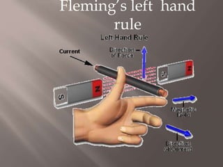
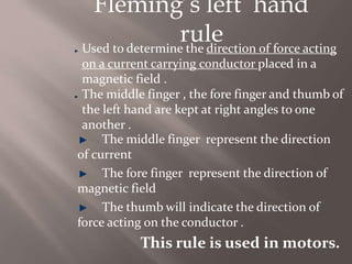


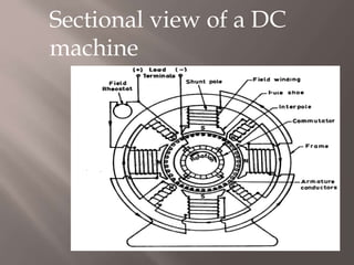
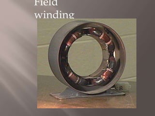
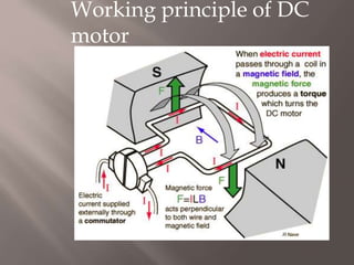

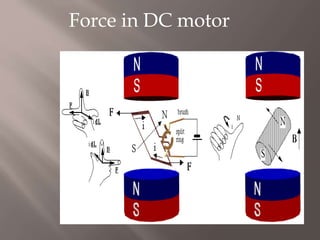


Fleming's left hand rule is used to determine the direction of force acting on a current carrying conductor placed in a magnetic field. The middle finger represents the direction of current, the forefinger represents the direction of the magnetic field, and the thumb indicates the direction of the force acting on the conductor. This rule is used in motors. DC motors are used in applications requiring constant torque, rapid acceleration/deceleration, and responsiveness to feedback signals, such as electric vehicles, steel/aluminum mills, trains, cranes, and controls. DC motors consist of a commutator, armature, and field windings that generate a magnetic field to cause rotation.


![D.c. machine[1]](https://cdn.slidesharecdn.com/ss_thumbnails/d-160420172313-thumbnail.jpg?width=640&height=640&fit=bounds)


