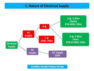
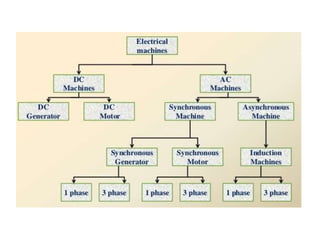
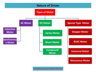
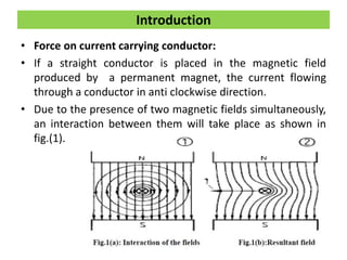
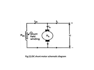
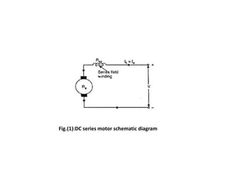
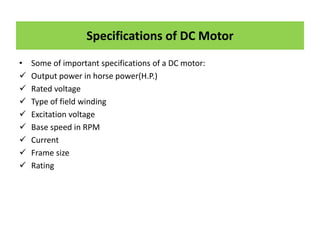
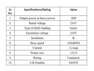
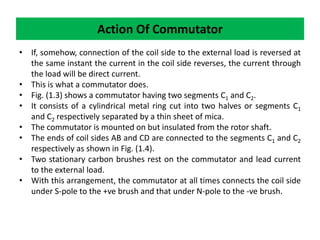
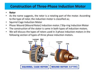
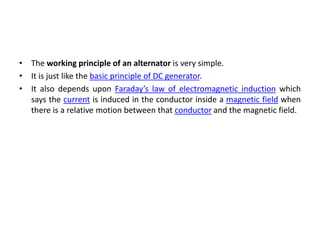
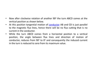
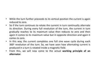
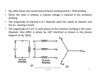
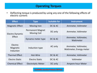
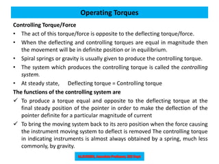
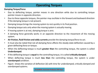
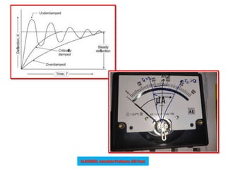
This document discusses the principles and applications of various electrical machines, focusing on DC motors and generators, including their construction, operation, and classifications. It outlines the specifics of different types of DC motors (shunt, series, and compound) along with their uses in industrial applications. It also covers the operation of DC generators, emphasizing their importance in converting mechanical energy to electrical energy, and explains the components such as the armature and field system.

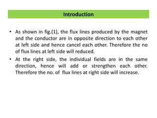


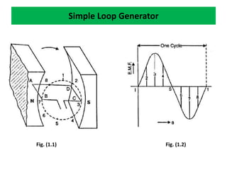
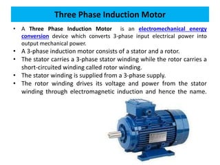
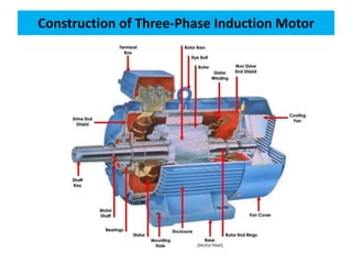
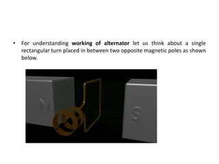
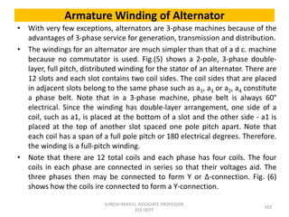
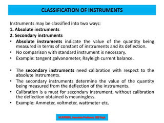
![• Consider a single turn loop ABCD rotating clockwise in a uniform magnetic
field with a constant speed as shown in Fig.(1.1).
• As the loop rotates, the flux linking the coil sides AB and CD changes
continuously.
• Hence the e.m.f. induced in these coil sides also changes but the e.m.f.
induced in one coil side adds to that induced in the other.
When the loop is in position no. 1 [See Fig. 1.1], the generated e.m.f. is zero
because the coil sides (AB and CD) are cutting no flux but are moving
parallel to it
When the loop is in position no. 2, the coil sides are moving at an angle to
the flux and, therefore, a low e.m.f. is generated as indicated by point 2 in
Fig. (1.2).
Simple Loop Generator](https://image.slidesharecdn.com/beeeunit-ii-240723052601-cc1b2b5b/85/BEEE-UNIT-II-ELECTRICAL-MACHINES-MEASUREMING-INSTRUMENTS-35-320.jpg)
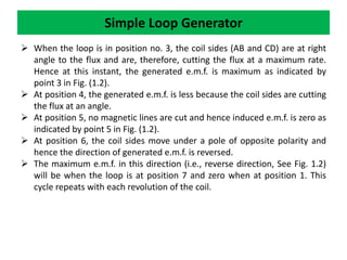
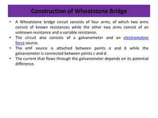
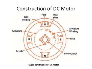
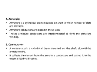
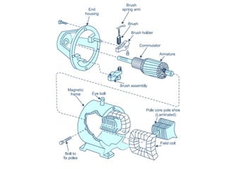
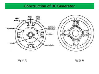
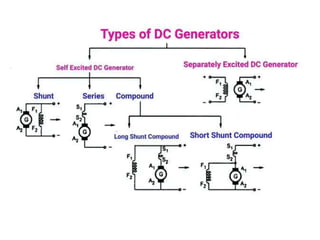
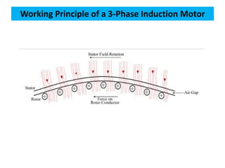
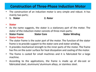
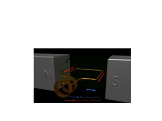
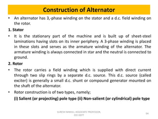
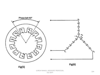
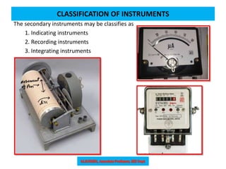
![Construction of DC Generator
• The d.c. generators and d.c. motors have the same general construction.
• In fact, when the machine is being assembled, the workmen usually do
not know whether it is a d.c. generator or motor.
• Any d.c. generator can be run as a d.c. motor and vice-versa.
• All d.c. machines have five principal components viz.,
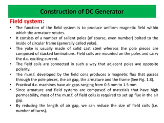
field system
armature core
armature winding
commutator
brushes [See Fig. 1.7].](https://image.slidesharecdn.com/beeeunit-ii-240723052601-cc1b2b5b/85/BEEE-UNIT-II-ELECTRICAL-MACHINES-MEASUREMING-INSTRUMENTS-41-320.jpg)


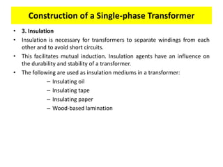
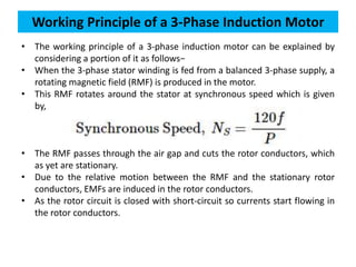
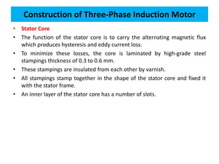

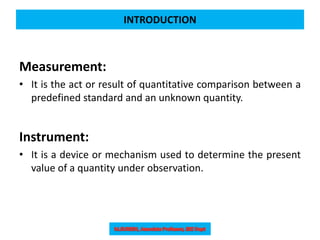
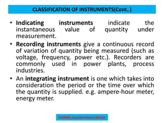
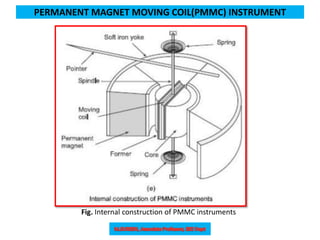
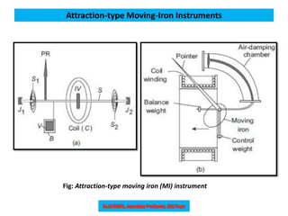
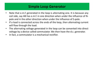
![PMMC Principle of Operation
• The principle on which a Permanent Magnet Moving Coil (PMMC) instrument
operates is that a torque is exerted on a current-carrying coil placed in the
field of a permanent magnet.
• A PMMC instrument is shown in Fig. The coil C has a number of turns of thin
insulated wires wound on a rectangular aluminium former F.
• The frame is carried on a spindle S mounted in jewel bearings J1, J2.
• A pointer PR is attached to the spindle so that it moves over a calibrated
scale.
• The whole of the moving system is made as light in weight as possible to keep
the friction at the bearing to a minimum.
• The coil is free to rotate in air gaps formed between the shaped soft-iron pole
piece (pp) of a permanent magnet PM and a fixed soft-iron cylindrical core IC
[Fig.(b)].
• The core serves two purposes;
(a) it intensifies the magnetic field by reducing the length of the air gap
(b) it makes the field radial and uniform in the air gap.](https://image.slidesharecdn.com/beeeunit-ii-240723052601-cc1b2b5b/85/BEEE-UNIT-II-ELECTRICAL-MACHINES-MEASUREMING-INSTRUMENTS-120-320.jpg)
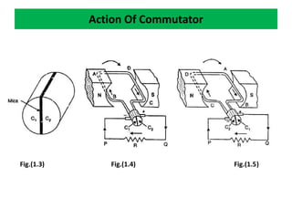
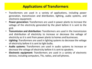
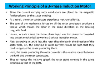
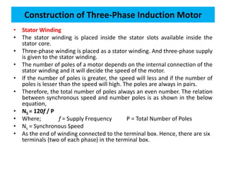
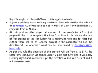
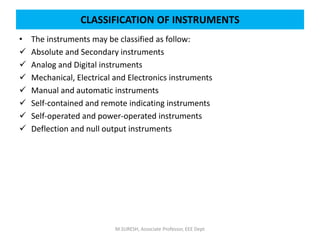
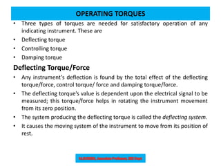
![PMMC Principle of Operation (Cont..)
• Thus, the coil always moves at right angles to the magnetic field [Fig.(c)].
• Modern permanent magnets are made of steel alloys which are difficult to
machine.
• Soft-iron pole pieces (pp) are attached to the permanent magnet PM for
easy machining in order to adjust the length of the air gap.
• Fig.(d) shows the internal parts and Fig.(e) shows schematic of internal
parts of a moving-coil instrument.
• A soft-iron yoke (Y ) is used to complete the flux path and to provide
shielding from stray external fields.](https://image.slidesharecdn.com/beeeunit-ii-240723052601-cc1b2b5b/85/BEEE-UNIT-II-ELECTRICAL-MACHINES-MEASUREMING-INSTRUMENTS-121-320.jpg)