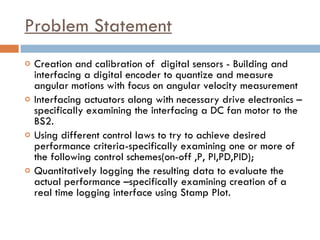
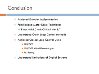
IMPLEMENTATION  OF A  DC MOTOR SPEED CONTROL MAE 576 [MECHATRONICS] LAB-3 GROUP E Chembrammel  Elavunkal  Srinivasan  Vishwajeet University at Buffalo, Mechatronics, Spring 2010
Problem Statement Creation and calibration of  digital sensors - Building and interfacing a digital encoder to quantize and measure angular motions with focus on angular velocity measurement Interfacing actuators along with necessary drive electronics –specifically examining the interfacing a DC fan motor to the BS2. Using different control laws to try to achieve desired performance criteria-specifically examining one or more of the following control schemes(on-off ,P, PI,PD,PID); Quantitatively logging the resulting data to evaluate the actual performance –specifically examining creation of a real time logging interface using Stamp Plot.
Flow Chart
Plant layout
Circuit Diagram Motor
System implementation
Calibration of optical switch For white back ground The binary value of the voltage switched states at 9mm The range of operation is between 5mm and 9mm
For Black back ground CALIBRATION OF OPTICAL SWITCH CONTD .
The encoder  Made out of QRB1114 The number of gradations on the reflecting disc is 24 to get a count of 12 cycles per revolution  Gives better RPM / count by the optical sensor
Measurement Authenticity PIN High PWM (255 Duty) MAX RPM = 6500 +/- 10% MAX VOLT = 10V RPM = 10/12 X 6500 = 5400
Motor drive The motor is driven using PWM values changing the duty cycle PWM RPM Range of operation Calibration of PWM drive
PWM drive calibration result The PWM cannot drive the motor below the 34% duty-cycle, which corresponds to 1.7 volts for the amplifier gain of 2. This corresponds to a cut-off voltage of 3.5V of the motor, and a motor speed of 1000 rpm.  The range of operation of the motor is 34% to 100% of maximum duty cycle of the input signal.
Tachometer testing 12V Input Low noise high noise 50 ms sampling time 100 ms sampling time Tachometer calibration
On-OFF control 1000 ms 100 ms 50 ms
Differential Gap Control Differential gap
P control
PI Control
PD Control
PID Control
Conclusion Achieved Encoder Implementation Familiarized Motor Drive Techniques PWM with RC with OPAMP with BJT Understood Open Loop Control methods Achieved Closed Loop Control Using ON/OFF ON/OFF with differential gap PID family Understood Limitations of Digital Systems

Lab - 3 - DC Motor Control

  • 1.
    IMPLEMENTATION OFA DC MOTOR SPEED CONTROL MAE 576 [MECHATRONICS] LAB-3 GROUP E Chembrammel Elavunkal Srinivasan Vishwajeet University at Buffalo, Mechatronics, Spring 2010
  • 2.
    Problem Statement Creationand calibration of digital sensors - Building and interfacing a digital encoder to quantize and measure angular motions with focus on angular velocity measurement Interfacing actuators along with necessary drive electronics –specifically examining the interfacing a DC fan motor to the BS2. Using different control laws to try to achieve desired performance criteria-specifically examining one or more of the following control schemes(on-off ,P, PI,PD,PID); Quantitatively logging the resulting data to evaluate the actual performance –specifically examining creation of a real time logging interface using Stamp Plot.
  • 3.
  • 4.
  • 5.
  • 6.
  • 7.
    Calibration of opticalswitch For white back ground The binary value of the voltage switched states at 9mm The range of operation is between 5mm and 9mm
  • 8.
    For Black background CALIBRATION OF OPTICAL SWITCH CONTD .
  • 9.
    The encoder Made out of QRB1114 The number of gradations on the reflecting disc is 24 to get a count of 12 cycles per revolution Gives better RPM / count by the optical sensor
  • 10.
    Measurement Authenticity PINHigh PWM (255 Duty) MAX RPM = 6500 +/- 10% MAX VOLT = 10V RPM = 10/12 X 6500 = 5400
  • 11.
    Motor drive Themotor is driven using PWM values changing the duty cycle PWM RPM Range of operation Calibration of PWM drive
  • 12.
    PWM drive calibrationresult The PWM cannot drive the motor below the 34% duty-cycle, which corresponds to 1.7 volts for the amplifier gain of 2. This corresponds to a cut-off voltage of 3.5V of the motor, and a motor speed of 1000 rpm. The range of operation of the motor is 34% to 100% of maximum duty cycle of the input signal.
  • 13.
    Tachometer testing 12VInput Low noise high noise 50 ms sampling time 100 ms sampling time Tachometer calibration
  • 14.
    On-OFF control 1000ms 100 ms 50 ms
  • 15.
    Differential Gap ControlDifferential gap
  • 16.
  • 17.
  • 18.
  • 19.
  • 20.
    Conclusion Achieved EncoderImplementation Familiarized Motor Drive Techniques PWM with RC with OPAMP with BJT Understood Open Loop Control methods Achieved Closed Loop Control Using ON/OFF ON/OFF with differential gap PID family Understood Limitations of Digital Systems