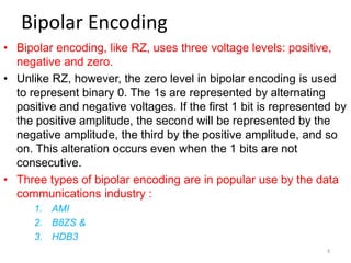
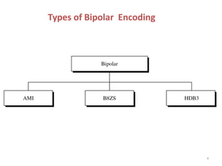
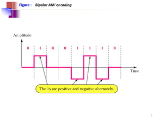
Introduction to Data communication
Topic : Bipolar Codes
Lecture #7
Dr Rajiv Srivastava
Director
Sagar Institute of Research & Technology (SIRT)
Sagar Group of Institutions, Bhopal
http://www.sirtbhopal.ac.in
Unit 1
Lecture 7
2
Bipolar Encoding
• Bipolar encoding, like RZ, uses three voltage levels: positive,
negative and zero.
• Unlike RZ, however, the zero level in bipolar encoding is used
to represent binary 0. The 1s are represented by alternating
positive and negative voltages. If the first 1 bit is represented by
the positive amplitude, the second will be represented by the
negative amplitude, the third by the positive amplitude, and so
on. This alteration occurs even when the 1 bits are not
consecutive.
• Three types of bipolar encoding are in popular use by the data
communications industry :
1. AMI
2. B8ZS &
3. HDB3
3
Types of Bipolar Encoding
4
In bipolar encoding, we use three levels:
positive, zero & negative.
Tip
5
Bipolar AMI
• Bipolar alternate mark inversion (AMI) is the
simplest type of bipolar encoding. In the name
alternate mark inversion, the word mark comes
from telegraphy and means 1.
– So AMI means alternate 1 inversion.
– A neutral, zero voltage represents binary 0.
• Binary 1s are represented by alternating positive
and negative voltages. Figure gives an example.
6
Figure : Bipolar AMI encoding
7
AMI with Pseudoternary variation
• A variation of bipolar AMI is called
Pseudoternary, in which binary 0 alternates
between positive and negative voltages.
• By inverting on each occurrence of a 1, bipolar
AMI accomplishes two things :
1. first, the DC component is zero, and
2. second, a long sequence of 1s stays synchronized
• However, there is no mechanism to ensure the
synchronization of a long string of 0s.
8
Figure: Bipolar schemes: AMI and pseudoternary
 In Bipolar AMI encoding, we use three levels: positive,
zero & negative
 Pseudoternary AMI
 1 represented by absence of signals
 0 represented by alternating positive & negative
 Used in DS1 & E1 lines
Various Encoding Schemes
• Two variations of bipolar AMI have been
developed to solve the problem of
synchronizing sequential 0s, especially for
long-distance transmission.
1. The first, used in North America, is called
bipolar 8-zero substitution (B8ZS).
2. The second, used in Europe and Japan, is called
high-density bipolar 3 (HDB3).
• Both are adaptations of bipolar AMI that
modify the original pattern only in the case of
multiple consecutives 0s.
11
Bipolar 8-Zero Substitution (B8ZS)
• B8ZS is the convention adopted in North America to
provide synchronization of long strings of 0s.
• In this technique. Eight consecutive zero-level
voltages are replaced by the sequence 000VB0VB.
• The V is the sequence denotes violation; this is non-
zero voltage that breaks the AMI rule of
encoding(opposite polarity from the previous).
• The B in the sequence denotes bipolar, which means
a non zero level voltage in accordance with the AMI
rule.
• The two cases are shown in the figure. 12
Figure: Two cases of B8ZS scrambling technique
- V means the same polarity as the polarity of previous non zero pulse
- B means the polarity opposite to the polarity of previous non zero pulse
Example : Using B8ZS, encode the bit stream
10000000000100. Assume that the polarity of the
first 1 is positive.
• Solution
•
1 0 0 0 0 0 0 0 0 0 0 1 0 0
v B
0 0 0 0
B V
Polarity changes on
every next 1 using AMI
Amplitude
time
High-Density Bipolar3 (HDB3)
• The problem of synchronizing strings of consecutive
0s is solved differently in Europe and Japan than in
the United States. This convention, called HDB3,
introduces changes into the bipolar AMI pattern
every time four consecutive 0s are encountered
instead of waiting for the eight expected by B8ZS in
North America.
• Although the name is HDB3, the pattern changes
whenever there are four 0s in succession.
15
• This technique is more conservative than B8ZS
• The 4 consecutive zero level voltages are replaced with a
sequence of 000V or B00V
• The reason for two different substitutions is to maintain
the even no of non zero pulses after each substitution.
• The two rules can be stated below:
1. If the no of non zero pulses after the last substitution is odd, the
substitution pattern will be 000V, which makes the total no of
non zero pulses even.
2. If the no of non zero pulses after the last substitution is even,
the substitution pattern will be B00V, which makes the total no
of non zero pulses even.
• Figure shows the example.
16
Figure: Different situations in HDB3 scrambling technique
Important : After the first substitution the polarity of 1 is
changed as per AMI scheme. Which is followed after each
substitution.
Example : Using HDB3, encode the bit stream
10000000000100. Assume that the number of 1s
so far is odd and the first 1 is positive.
• Solution
•
1 0 0 0 0 0 0 0 0 0 0 1 0 0
v
0 0 0 0 0
B V
Amplitude
time
Combined Look At Bipolar AMI, B8ZS
and HDB3
Thank You
Dr Rajiv Srivastava
Director
Sagar Institute of Research & Technology (SIRT)
Sagar Group of Institutions, Bhopal
http://www.sirtbhopal.ac.in

Data Communication & Computer network: Bipolar codes

  • 1.
    Introduction to Datacommunication Topic : Bipolar Codes Lecture #7 Dr Rajiv Srivastava Director Sagar Institute of Research & Technology (SIRT) Sagar Group of Institutions, Bhopal http://www.sirtbhopal.ac.in
  • 2.
  • 3.
    Bipolar Encoding • Bipolarencoding, like RZ, uses three voltage levels: positive, negative and zero. • Unlike RZ, however, the zero level in bipolar encoding is used to represent binary 0. The 1s are represented by alternating positive and negative voltages. If the first 1 bit is represented by the positive amplitude, the second will be represented by the negative amplitude, the third by the positive amplitude, and so on. This alteration occurs even when the 1 bits are not consecutive. • Three types of bipolar encoding are in popular use by the data communications industry : 1. AMI 2. B8ZS & 3. HDB3 3
  • 4.
    Types of BipolarEncoding 4
  • 5.
    In bipolar encoding,we use three levels: positive, zero & negative. Tip 5
  • 6.
    Bipolar AMI • Bipolaralternate mark inversion (AMI) is the simplest type of bipolar encoding. In the name alternate mark inversion, the word mark comes from telegraphy and means 1. – So AMI means alternate 1 inversion. – A neutral, zero voltage represents binary 0. • Binary 1s are represented by alternating positive and negative voltages. Figure gives an example. 6
  • 7.
    Figure : BipolarAMI encoding 7
  • 8.
    AMI with Pseudoternaryvariation • A variation of bipolar AMI is called Pseudoternary, in which binary 0 alternates between positive and negative voltages. • By inverting on each occurrence of a 1, bipolar AMI accomplishes two things : 1. first, the DC component is zero, and 2. second, a long sequence of 1s stays synchronized • However, there is no mechanism to ensure the synchronization of a long string of 0s. 8
  • 9.
    Figure: Bipolar schemes:AMI and pseudoternary  In Bipolar AMI encoding, we use three levels: positive, zero & negative  Pseudoternary AMI  1 represented by absence of signals  0 represented by alternating positive & negative  Used in DS1 & E1 lines
  • 10.
  • 11.
    • Two variationsof bipolar AMI have been developed to solve the problem of synchronizing sequential 0s, especially for long-distance transmission. 1. The first, used in North America, is called bipolar 8-zero substitution (B8ZS). 2. The second, used in Europe and Japan, is called high-density bipolar 3 (HDB3). • Both are adaptations of bipolar AMI that modify the original pattern only in the case of multiple consecutives 0s. 11
  • 12.
    Bipolar 8-Zero Substitution(B8ZS) • B8ZS is the convention adopted in North America to provide synchronization of long strings of 0s. • In this technique. Eight consecutive zero-level voltages are replaced by the sequence 000VB0VB. • The V is the sequence denotes violation; this is non- zero voltage that breaks the AMI rule of encoding(opposite polarity from the previous). • The B in the sequence denotes bipolar, which means a non zero level voltage in accordance with the AMI rule. • The two cases are shown in the figure. 12
  • 13.
    Figure: Two casesof B8ZS scrambling technique - V means the same polarity as the polarity of previous non zero pulse - B means the polarity opposite to the polarity of previous non zero pulse
  • 14.
    Example : UsingB8ZS, encode the bit stream 10000000000100. Assume that the polarity of the first 1 is positive. • Solution • 1 0 0 0 0 0 0 0 0 0 0 1 0 0 v B 0 0 0 0 B V Polarity changes on every next 1 using AMI Amplitude time
  • 15.
    High-Density Bipolar3 (HDB3) •The problem of synchronizing strings of consecutive 0s is solved differently in Europe and Japan than in the United States. This convention, called HDB3, introduces changes into the bipolar AMI pattern every time four consecutive 0s are encountered instead of waiting for the eight expected by B8ZS in North America. • Although the name is HDB3, the pattern changes whenever there are four 0s in succession. 15
  • 16.
    • This techniqueis more conservative than B8ZS • The 4 consecutive zero level voltages are replaced with a sequence of 000V or B00V • The reason for two different substitutions is to maintain the even no of non zero pulses after each substitution. • The two rules can be stated below: 1. If the no of non zero pulses after the last substitution is odd, the substitution pattern will be 000V, which makes the total no of non zero pulses even. 2. If the no of non zero pulses after the last substitution is even, the substitution pattern will be B00V, which makes the total no of non zero pulses even. • Figure shows the example. 16
  • 17.
    Figure: Different situationsin HDB3 scrambling technique Important : After the first substitution the polarity of 1 is changed as per AMI scheme. Which is followed after each substitution.
  • 18.
    Example : UsingHDB3, encode the bit stream 10000000000100. Assume that the number of 1s so far is odd and the first 1 is positive. • Solution • 1 0 0 0 0 0 0 0 0 0 0 1 0 0 v 0 0 0 0 0 B V Amplitude time
  • 19.
    Combined Look AtBipolar AMI, B8ZS and HDB3
  • 20.
    Thank You Dr RajivSrivastava Director Sagar Institute of Research & Technology (SIRT) Sagar Group of Institutions, Bhopal http://www.sirtbhopal.ac.in