Download to read offline
![IOSR Journal of Electrical and Electronics Engineering (IOSR-JEEE)
e-ISSN: 2278-1676,p-ISSN: 2320-3331, Volume 10, Issue 4 Ver. III (July – Aug. 2015), PP 21-35
www.iosrjournals.org
DOI: 10.9790/1676-10432135 www.iosrjournals.org 21 | Page
SVC Placement in Unbalanced Distribution Network to Reduce
the Neutral Lines Current and Ohmic Losses Using Intelligent
Optimization Algorithms
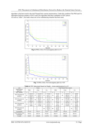
Saeed Rezaeian Marjani, Vahid Talavat
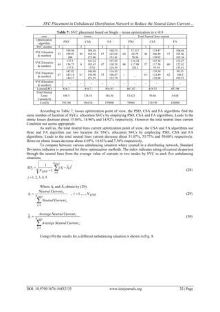
(Department of Electrical Engineering, Urmia University, Urmia, Iran)
Abstract: Distribution Network (DN) unbalancing and their unfavorable effects such as energy losses is an
important challenge in electrical engineering. The system unbalancing problem is highly regarded due to
increasing energy costs in DN. In this paper, the use of SVC (Static Var Compensation) is to improve the
unbalancing and reducing the energy losses in DN. To handle power flow procedure, a novel circuit solution is
presented to modeling the DN unbalancing situations. Furthermore, the nominal active and reactive loads in
different phases have been multiplied into a specified value which is defined by the Unbalancing Factor (UF).
Intelligent optimization algorithms such as PSO (Particle Swarm Optimization), CSA (Cuckoo Search
Algorithm) and FA (Firefly Algorithm) are used to optimal sitting and sizing of the SVC with a three terms
objective function, including losses, Neutral Lines Current and SVC installation cost in the distribution
networks. The effect of SVC number installation in DN is evaluated. To demonstrate the effectiveness of the
proposed method, the modified standard IEEE 123 nodes network has been tested. Simulations are carried out
in two options. The results verify the ability of presented method to improve the performance of the unbalance
distribution network significantly.
Keywords: CSA, Energy Losses, FA, Neutral Lines Current, PSO, SVC, Unbalance Distribution network
I. Introduction
Power generated in plants delivers to the electricity consumers through the transmission, sub
transmission and distribution lines. The consumable loads is always non-uniform and is normally unbalanced
due to accidental and un-simultaneous behavior of them in a DN. System unbalance will have adverse effects
such as unbalance three Phase voltages, increase energy losses and occupation feeder capacity in DN [1, 2, 3].
It is clear that the minimum energy loss is obtained in balanced three phase currents situation.
Moreover, in an unbalancing system, returned flow in neutral wire, increases the Ohmic losses in the neutral
conductor and copper and iron losses in distribution transformers [4].
FACTS (Flexible AC Transmission Systems) devices were introduced to increase the capacity of
transmission lines and optimal operation of the power system in the recent years [5].
The custom FACTS devices are unsuitable in size and cost for applications in DN. Some of FACTS
devices are introduced in suitable capacities to use in DN, such as D-STATCOM and SVC [6, 7]. The number,
locations, and ratings of FACTS devices because of installation cost, must be specified carefully to provide the
maximum benefit to the network.
In order to solve load balancing and reactive power compensation introduce the method to use SVCs
with four-wire three-phase loads [8]. A combined reactive power compensation method of a static Var
compensator (SVC) consists of star and delta connected thyristor controlled reactors and a series active filter is
described for unbalanced three-phase four-wire distribution feeders with Harmonic distortion presented in [9].
In [10] a mathematical model proposed for computer simulation and control of a delta-connected SVC to
achieve the purpose of negative-sequence reduction. In [11] introduced Load Compensate in the unbalanced
distributed network by appropriate D-STATCOM design. Determine the appropriate place SVC using genetic
algorithm to meet load unbalancing and network in [3]; some works have been proposed to fix an unbalancing
load and distribution network problems using D-FACTS In the literature.
Recently, many methods based on artificial intelligence have been developed for solving optimal
location of FACTS and D-FACTS devices problems such as tabu search algorithm [12], Particle Swarm
optimization [13, 14], Genetic Algorithm, [15] Gravitational Search Algorithm [16], firefly Algorithm [2],
Differential Evolution Techniques [13].
DN unbalancing Improvement point of view the maximum decreasing of the Neutral lines current
while decreasing the Energy losses by optimal SVC allocation placement distributing networks using three
intelligent algorithm consist of cuckoo search algorithm (CSA), PSO and FA has been discussed in this paper.](https://image.slidesharecdn.com/d010432135-160706045908/85/D010432135-1-320.jpg)
![SVC Placement in Unbalanced Distribution Network to Reduce the Neutral Lines Current…
DOI: 10.9790/1676-10432135 www.iosrjournals.org 22 | Page
The paper is organized as follows. Section 2 explains the model of SVC. In Section 3 intelligent
Optimization Algorithm is presented. In Section 4, The Proposed SVC Placement Algorithm, including the
objective function, The Proposed Method to Modeling the Unbalancing in Distribution Networks and the Four-
Wire Modeling in Distribution Networks Power Flow, is developed. In Section 5, Simulation Results and
Numerical Studies have been reported. Section 6 contains the Effect of the various SVC Number in system
Unbalancing Improvement and Reduction energy Losses according to propped method followed by conclusions.
II. Static Var Compensator (SVC)
SVC is one of various FACTS devices which are connected in parallel to the distribution network
nodes and acts as injection or absorbing Static reactive power source. Basically SVC output changes between
the inductive or capacitive currents to control various parameters such as network nodes voltage. In the simplest
structure SVC consists of a parallel combination of controlled inductor with thyristor valves switches and
capacitor banks. In terms of performance it is like a variable parallel reactance which by controlling the firing
angle of the thyristors becomes a highly responded capable device [17, 18].
Fig. 1: Circuit model of SVC
Fig. 1 shows an equivalent circuit of SVC. The equipollent reactance to controlled inductor through
thyristor can be expressed by:
)2sin()(2
L
L
X
X )1(
SVC equivalent reactance of the parallel combination of thyristor controlled inductors and capacitor
can be obtained by:
LC
LC
Leq
XX
XX
X
))2sin()(2(
)2(
Where, XC is the parallel capacitor reactance and α is the fire angle of the thyristors. Considering (2),
SVC equivalent Susceptance that is a function of angle firing of thyristors is obtained in (3):
LC
CL
eq
XX
XX
B
))2sin()(2(
)3(
According to (3), unlike the capacitor, Susceptance of SVC is a continuous function of the angle fire of
the thyristors [17].
Injection or absorbing of reactive power by SVC using (4) is calculated:
eqSVC BVQ 2
)4(
In (4), V is the voltage of the node that SVC is installed.
III. Intelligent Optimization Algorithms
A comprehensive study carried out to optimal SVC allocation using three different types of intelligent
optimization algorithms. Main objective is reduction Neutral Lines Current and reduction losses, considering
SVC installing cost in network. In this section PSO, CSA and FA optimization Algorithms has been introduced.
3.1 Particle Swarm Optimization (PSO)
PSO is an evolutionary algorithm which was presented in 1995 by Eberhart & Kennedy. This algorithm
has strong global search capability and the ability to solve the different optimization problems in the multi-
dimensional and nonlinear search space [19].](https://image.slidesharecdn.com/d010432135-160706045908/85/D010432135-2-320.jpg)
![SVC Placement in Unbalanced Distribution Network to Reduce the Neutral Lines Current…
DOI: 10.9790/1676-10432135 www.iosrjournals.org 23 | Page
Simplicity, produce high-quality solutions in less time, Similar flexibility for control, stability study of
local and global search space compared with other algorithms, also fast convergence are some advantage of this
algorithm in power system [20].
In this algorithm, the population of people with R unknown parameters are used in optimization. In
other words, each particle represents a solution of the problem and the appropriate amount of each particle the
each iteration is calculated by choice of objective function [21]. Basically, each particle found the best deal by
itself and knows its location (pbest) furthermore each particle knows The best obtained value among all the
particles (gbest) so the direction and rate of movement of each particle based on previous speed and location is
determined by the pbest and gbest . With this amount, the particles are guided in the optimal or near-optimal
solutions. This shift can be shown based on speed changing idea. Position vector and velocity vector of the
particle can be shown with the help of position and velocity of the particle in the d - dimensional search space as
shown Xi = [xi1, xi2… xid] and Vi = [vi1, vi2… vid] [18, 22].
As a result the speed of the particles changes according to (5):
)(2)(1 21
1
k
i
k
i
k
i
k
i
xGbestrandcxPbestrandc
wVV
)5(
In (5), Vi
K
is the speed of the particle in kth iteration, w is Constant weight, c1 and c2 is Acceleration
coefficients that indicate how the particle moves to the best location and best global position, rand is Random
number between 0 and 1, and xi
K
is the position of ith
particle in kth iteration. Considering (5), particles changes
speed the each iteration.
Typically, the particle speed is limited in specified range and the changed position of each particle
calculated according to velocity vector as:
11
k
i
k
i
k
i Vxx )6(
Pseudo code of implementation PSO presented as follows [23]:
Initialization
Parameters and size of the swarm (S);
Randomly initialize particle position and velocities;
For Each particle,
Let pbestid = xid
Calculate f (xid) of each particle;
Calculate gbest, // the best of pbestid;
While (maximum iterations or minimum error criteria is not met) {
For (i=1 to S) {
Calculate the new velocity using (5);
Calculate the new position using (6);
Calculate f (xid) of each particle;
If (f (xid) <f (pbestid))
Pbestid = xid, // Minimization case;
If (f (pbestid) <f (gbestd))
gbestd = pbestd;
}
}
Show the best solution found gbestd;
3.2 Cuckoo search algorithm (CSA)
Cuckoo search algorithm (CSA) is one of the most recently defined algorithms by Yang and Deb [24,
25] where inspired by the obligate brood parasitism of some cuckoo species by laying their eggs in the nests of
other host birds [27].
Two main operations are building the structure of the CSA, (i) a direct search based on Lévy flights,
(ii) a random search based on the probability for a host bird to discover an alien egg in its nest [26], During the
search process, CSA is following three idealized rules: (i) each cuckoo lays one egg at a time, and dump its egg
in randomly chosen nest; (ii) the best nests with better eggs (better solution) will carry over to the next
generations and (iii) available host nests is a constant number, and the egg laid by a cuckoo is discovered by the](https://image.slidesharecdn.com/d010432135-160706045908/85/D010432135-3-320.jpg)
![SVC Placement in Unbalanced Distribution Network to Reduce the Neutral Lines Current…
DOI: 10.9790/1676-10432135 www.iosrjournals.org 24 | Page
host bird with a probability pa ∈ [0, 1]. In this case, the host bird can either throw the egg away or abandon the
nest and build a completely new nest [24, 25].
Pseudo code of implementation Cuckoo Search via lévy flights presented as follows [27]:
Begin
Generation t = 1;
Initialized with random vector values, and initialize parameters NP (Number Population), D;
Evaluate fitness for every individual and determine the best individual with the best objective value;
While (stopping criterion is not met)
Get a Cuckoo randomly by lévy flights;
Evaluate fitness for the cuckoo F;
Choose a nest among n (say, j) randomly;
If (Fi > Fj)
Replace j by the new solution;
End if
A fraction (pa) of worse nests is abandoned and new ones are built;
Keep the best solution;
Rank the solutions and find the current best;
Update the generation number t = t + 1;
End while
End.
In the CSA each solution is shown as egg in a nest, and a cuckoo egg represent a new solution. The
object is to use the potentially better solutions (cuckoos egg) to replace non-dominate solution in the nests.
Similar to many other meta-heuristic search methods, in the initial process, each solution is generated randomly,
The initial population of the host nests is set to best value of each nest Xbestd (d = 1,…, D). The cuckoo
randomly chooses the nest position to lay egg, in other words the next newly generated solution form D
dimension optimization problem is expressed as:
)(1
DrandnstepsizeXX t
d
t
d
(7)
Where in (7) α is a random number generated between [−1, 1], and
)(01.0 d
t
d XbestXstepStepsize (8)
Where
/1
)(
)()(
Drandn
LevyDrandn
Step
(9)
The randn [D] function generates a Gaussian distribution between [1, D]. Levy (λ) obtain from (10)
1
2
)1(
2)
2
1
(
)
2
sin()1(
)(
Levy (10)
Where λ is a constant (1 < λ ≤ 3) and Γ is gamma function. A Lévy flight is a random walk. After
producing the new solution based on above procedure, it will be compared to the Xd
t
, if the introduced objective
function value of the new solution is smaller than the objective function value of Xd
t
, the new solution is
accepted. Otherwise Xd
t
remains as the best solution.
For the newly obtained solution, its lower and upper limits should be satisfied according to [26]:
1
1
t
di
new
di
new
di
t
di
X
LbXifLb
UbXifUb
X (11)](https://image.slidesharecdn.com/d010432135-160706045908/85/D010432135-4-320.jpg)
![SVC Placement in Unbalanced Distribution Network to Reduce the Neutral Lines Current…
DOI: 10.9790/1676-10432135 www.iosrjournals.org 25 | Page
The other part of cuckoo search is to place some nests by constructing a new solution. The egg is
discovered by the host bird by comparing randomly (i.e. probability Pa ∈ [0, 1]). If the host bird discovers the
alien egg, the host bird can either throw the egg away or abandon the nest, and build a completely new this
crossover operator is shown as Follows [24, 28]:
otherwiseX
PrandLbUbrandX
X
t
d
ai
t
ddis
d
)(
(12)
It can be concluded, CSA good converge behavior is related to three control parameters namely cuckoo
nest population size, maximum generation. Optimally setting of these parameters leads to yield better solution
and lesser computational time.
3.3 Firefly Algorithm (FA)
Firefly algorithm (FA) is a novel nature-inspired meta-heuristic and powerful algorithm that solves the
continuous constrained optimization problems. This algorithm was first developed by Xin-She Yang in late
2007 and 2008 at Cambridge University which was based on the social behavior of fireflies [2, 29].
FA uses the three idealized rules. These three rules are given as follows: (a) One firefly is be attracted
to other fireflies with assumption unisexual mode for them; (b) Attractiveness and brightness decrease as their
distance increases. For any two flashing fireflies if there is no brighter one than a particular firefly, it will move
randomly otherwise the less bright one will move towards the brighter one, and (c) Each firefly represents a
solution. Solution quality is specified by firefly brightness Based on the landscape of the objective function [29].
According to above rules, In FA the variation in light intensity, I, and the formulation of the
attractiveness β are two important parameters. In the simplest form and considering a fixed light absorption
coefficient γ, light intensity I, which is the function of distance r, can be expressed as (13):
2
0)( r
eIrI
(13)
Where I0 is the light intensity at r = 0 [2].
As a firefly’s attractiveness is proportional to the light intensity seen by adjacent fireflies, define the
variation of attractiveness β with the distance r by (14):
2
0)( r
er
(14)
Where β0 is the attractiveness at r = 0 [29].
The distance between any two fireflies i and j can be calculated using the Euclidean distance as:
Dd
djdijiij xxxxr 2
,, )( (15)
Where xi,d is the dth
component of the spatial coordinate x of the ith
firefly and D is the dimension of the
problem [2]. Therefore, the movement of firefly i to another more attractive (brighter) firefly j determined by
(16):
i
k
i
k
j
rk
i
k
i xxexx
k
ij
)(
2
0
1
(16)
Where α is the randomization parameter and ξ is a vector of random numbers drawn from a Gaussian
distribution or uniform distribution. [29].
Pseudo code of implementation FA presented as follows [2]:
Begin
Insert the objective function f(x), x=(x1, x2… xd)T
;
Initialize the fireflies population xi, i=1, 2… n;
Determine the light intensity Ii at xi using f (xi);
Set light absorption coefficient γ, randomize coefficient α;
While (t < MaxGeneration)
For i=1: n all n fireflies
For j=1: n
If (Ii < Ij), Move firefly I toward j; end if](https://image.slidesharecdn.com/d010432135-160706045908/85/D010432135-5-320.jpg)
![SVC Placement in Unbalanced Distribution Network to Reduce the Neutral Lines Current…
DOI: 10.9790/1676-10432135 www.iosrjournals.org 26 | Page
Vary attractiveness with distance r via exp [-γr2
];
Evaluate new solutions and update light intensity;
End for j
End for i
Rank the fireflies and find the current global best;
End while
End.
IV. The Proposed SVC Placement Algorithm
In this paper, the SVCs are located to improve the unbalancing situation and ohmic loss reduction in
distribution network. As well an innovative method is proposed to create different unbalancing status in
distribution network. Comprehensive objective function is defined as sum of three terms consist of the total
Neutral Lines Current, active power loss and SVC installation cost. Optimization results have been carried out
with PSO, CSA and FA methods.
4.1 Problem Formulation
The SVC placement problem in DN is formulated as a general objective function to minimize ohmic
losses, Neutral Lines Currents and SVC installation cost. The proposed objective function is given by:
332211 FFFFunctionObjective (17)
Where F1 is the losses in distribution network which is expressed as:
lossesPF 1 (18)
As well as F2 indicates the total Neutral Lines Current as is following:
LINEN
i
TiSiRi IIIF
1
2 (19)
In (19), NLine is lines number of distribution network and IRi, ISi and ITi are the current phasors in
different phases of ith
line.
The annual SVC installation cost in $/kVAr is determined by (20) [30]:
)38.1273051.00003.0(
1
2
3
i
N
i
i QQF
SVC
(20)
Where NSVC is the number of SVCs and Qi is the reactive power capacity of ith
SVC in MVAr.
It should be pointed out that the terms of objective function in (17) have not the same units, thus
Normalized Weight coefficients, β1, β2 and β3 are defined as follows:
lossPmax
1
3
1
(21)
LINEN
i
TiSiRi III
1
maxmaxmax
2
3
1
(22)
)38.1273051.00003.0(3
1
max
1
2
max
3
i
N
i
i QQ
SVC
(23)
Where Pmax loss is the maximum losses, IRimax, ISimax, ITimax are the three-phase lines current in
distribution network without SVCs and Qimax is the nominal SVC reactive power.](https://image.slidesharecdn.com/d010432135-160706045908/85/D010432135-6-320.jpg)
![SVC Placement in Unbalanced Distribution Network to Reduce the Neutral Lines Current…
DOI: 10.9790/1676-10432135 www.iosrjournals.org 27 | Page
4.2 The Proposed Method to Modeling the Unbalancing in Distribution Networks
The Neutral Lines Current values in unbalanced distribution networks are not neglected. This is
because of the single-phase loads and unequal drawn currents by various phases of load points in the real
distribution network. Furthermore, the non-zero Neutral lines currents increase losses in the networks.
For a more comprehensive study on the unbalanced network, a novel method is used to modeling the
unbalancing situation in distribution network.
For this purpose, in the proposed method, the nominal active and reactive loads in different phases
have been multiplied into a specified value which is defined by the unbalancing factor (UF). The specified
factor, which is shown in (24), is randomly developed in five diverse ranges of 0 to 1, 0.25 to 1, 0.5 to 1, 0.75 to
1 and 0.9 to 1.
9.0,75.0,5.0,25.0,0
)1(
x
rxxFactorgUnbalancin
(24)
Where, r is a random number between 0 and 1.
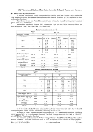
4.3 The Four-Wire Modeling in Distribution Networks Power Flow
Due to detailed analysis and study of the DNs and calculate the unknown voltage and currents of DN,
the method in [31] has been used. Forasmuch as the mentioned method is used for non-neutral network, the
modified method as in followed.
In order to obtain the lines currents and nodes voltage of the distribution network, four-wire segment of
the DN has been shown in Fig. 2.
In the above section, the relationship between nodes voltage and branches current is obtained from
(25): [32]
Fig. 2: Circuit model of the four-wire line DN
T
S
R
RST
TN
SN
RN
TN
SN
RN
I
I
I
Z
V
V
V
V
V
V
'
'
'
(25)
Where ZRST obtain from (26)
SsSmSm
SmSsSm
SmSmSs
RST
ZzZzZz
ZzZzZz
ZzZzZz
Z (26)
Where, zs and zm are the self-impedance of each line and the mutual-impedance between lines
respectively.
Based on definition, ZS is defined as follows:
mnsnS zzZ 2 (27)
Where, zsn and zmn are the self-impedance of Neutral lines and the mutual-impedance between Neutral
lines and other lines respectively.
In this study Forward-backward power flow has been employed [32].](https://image.slidesharecdn.com/d010432135-160706045908/85/D010432135-7-320.jpg)

![SVC Placement in Unbalanced Distribution Network to Reduce the Neutral Lines Current…
DOI: 10.9790/1676-10432135 www.iosrjournals.org 34 | Page
The used optimization algorithms were compared point of view optimal SVCs allocation and
Convergence speed in different UF value under proposed method.
It can be concluded from the simulation results that in point of view of main objective function
optimization and convergence speed, CSA is more efficient in the proposed method. But this does not mean the
performance of the two other algorithms is Inefficient. Because, in point of view of single term analysis of main
objective function and Single item objective function optimization, FA and PSO also have shown better
solution. This paper presented a comprehensive study about efficiency of various optimization algorithms in
proposed method.
In addition, the effect of raising the number of installed SVC’s in network is evaluated on reducing
network unbalancing and losses. So it can be seen usage of the SVC in DNs as an efficient and updated manner
to improve the DNs operation, which will increase the performance of networks efficiently.
References
[1]. Hussain S.M.S, Subbaramiah M, “An Analytical Approach for Optimal Location of DSTATCOM in Radial Distribution System,”
Energy Efficient Technologies for Sustainability (ICEETS), 2013 International Conference on.Trans. Roy. Soc. London, vol. A247,
pp. 529–551, April 1955. (References)
[2]. Azah Mohamed, Hussain Shareef, Hadi Zayandehroodi, “Optimum D-STATCOM Placement Using Firefly Algorithm for Power
Quality Enhancement,” 2013 IEEE 7th International Power Engineering and Optimization Conference (PEOCO2013), Langkawi,
Malaysia. 3-4 June 2013.
[3]. M. A. Talebi, A. Kazemi, A. Gholami, M. Rajabi, “optimal placement of static var compensators in distribution feeders for load
balancing by genetic,” Electricity Distribution, 2005. CIRED 2005 18th International Conference and Exhibition on.
[4]. M. A. Talebi, A. Kazemi, A. Gholami, M. Rajabi, “optimal placement of static var compensators in distribution feeders for load
balancing by genetic algorithm,” Electricity Distribution, 2005. CIRED 2005. 18th International Conference and Exhibition on.
[5]. Ya-Chin Chang, Rung-Fang Chang, “Maximization of Transmission System Loadability with Optimal FACTS Installation
Strategy,” J Electr Eng Technol Vol. 8, No. 5: 991-1001, 2013
[6]. A. Kazemi, S. Jamali, H. Shateri, “effects of dstatcom on measured impedance at source node of distribution feeder,” CIRED
Seminar 2008: SmartGrids for Distribution Frankfurt, 23 - 24 June 2008.
[7]. W.K. Wong, D.L.Osborn, J.L. McAvoy, “application of compact static var compensators to distribution systems,” IEEE
Transactions on Power Delivery, Vol. 5, No. 2, April 1990.
[8]. F.R. Quintela, J.M.G. Arévalo, R.C. Redondo, N.R. Melchor, “Four-wire three-phase load balancing with Static VAr
Compensators,” Electrical Power and Energy Systems 33 (2011) 562–568.
[9]. S.Y.Lee, C.J.Wu, “Reactive power compensation and load balancing for unbalanced three-phase four-wire system by a combined
system of an SVC and a series active filter,” Electric Power Applications, IEE Proceedings.
[10]. Jen-Hung Chen, Wei-Jen Lee, Mo-Shing Chen, “Using a Static Var Compensator to Balance a Distribution System,” IEEE
TRANSACTIONS ON INDUSTRY APPLICATIONS, VOL. 35, NO. 2, MARCH/APRIL 1999.
[11]. Wei-Neng Chang, Kuan-Dih Yeh, “Design of D-STATCOM for Fast Load Compensation of Unbalanced Distribution Systems,”
Power Electronics and Drive Systems, 2001. Proceedings, 2001 4th IEEE International Conference on.
[12]. HiroyuluMori, Hidenobu Tani, “Two-Staged Tabu Search for Determining Optimal Allocation of D-FACTS in Radial Distribution
Systems with Distributed Generation,” Transmission and Distribution Conference and Exhibition 2002: Asia Pacific. IEEE/PES.
[13]. M.Geethanjali, S.Devi, “Optimal Location and Sizing ofThyristor Controlled Series Capacitor in Radial Distribution Systems Using
Particle Swarm Optimizationand DifferentialEvolutionTechniques, “2013 International Conference on Power, Energy and Control
(ICPEC)
[14]. Amgad A. EL-Dib ∗, Hosam K.M. Youssef, M.M. EL-Metwally, Z. Osman, “Optimum VAR sizing and allocation using particle
swarm optimization,” Electric Power Systems Research 77 (2007) 965–972.
[15]. J.S. Huang, Z.H. Jiang, M. Negnevitsky, “Loadability of power systems and optimal SVC placement,” Electrical Power and Energy
Systems 45 (2013) 167–174.
[16]. Jayanti Sarker, S.K. Goswami, “Solution of multiple UPFC placement problems using Gravitational Search Algorithm,” Electrical
Power and Energy Systems 55 (2014) 531–541.
[17]. Ambriz-Perez, H., Acha, E., Fuerte-Esquivel, “Advanced SVC Models for Newton-Raphson Load Flow and Newton Optimal
Power Flow Studies,” C.R. PowerSystems, IEEE Transactions on.
[18]. Karami, M, Mariun, N, KadirM.Z.A, “Determining optimal location of Static Var Compensator by means of genetic algorithm,”
Electrical, Control and Computer Engineering (INECCE), 2011 International Conference on.
[19]. Bhowmik,A.R, Chakraborty,A.K; Das, P. “Optimal location of UPFC based on PSO algorithm considering active power loss
minimization,” Power India Conference, 2012 IEEE Fifth.
[20]. Varshney, Sarika, Srivastava, Laxmi, Pendit, Manjaree, “Comparison of PSO models for optimal placement and sizing of Statcom,”
Sustainable Energy and Intelligent Systems (SEISCON 2011) International Conference on.
[21]. Mondal, D, Chakrabarti, A. Sengupta, A. “PSO Based Location and Parameter setting of Advance SVC Controller with Comparison
to GA in Mitigating Small Signal Oscillations,” Energy, Automation, and Signal (ICEAS), 2011 International Conference on.
[22]. Debrup Das, Anish Prasai, Ronald G. Harley, Deepak Divan. “Optimal Placement of Distributed Facts Devices in Power Networks
Using Particle Swarm Optimization,” Energy Conversion Congress and Exposition, 2009. ECCE 2009. IEEE.
[23]. A. Gherboudj & S. Chikhi, “BPSO Algorithms for Knapsack Problem”. A. Özcan, J. Zizka, and D. Nagamalai (Eds.):
WiMo/CoNeCo 2011, CCIS 162, pp. 217–227, 2011. Springer (2011).
[24]. Yang, X.S., Deb, S, “Cuckoo search via Lévy flights”. Proc. World Congress on Nature & Biologically Inspired Computing (NaBIC
2009), IEEE Publications, USA, 2009, pp. 210–214.
[25]. Yang, X.S., Deb, S, “Engineering optimization by cuckoo search”, Int. J. Math. Model. Numer. Optimisation, 2010, 1, pp. 330–343.
[26]. Dieu N. Vo, Peter Schegner, Weerakorn Ongsakul, “Cuckoo search algorithm for non-convex economic dispatch,” Published in IET
Generation, Transmission & Distribution.
[27]. Xiangtao Li, Minghao Yin, “Modified cuckoo search algorithm with self-adaptive parameter method,” Information Sciences 298
(2015) journal homepage: www.else vier.com/locate/ins.
[28]. Attia A. El-Fergany, Almoataz Y. Abdelaziz, “Capacitor allocations in radial distribution networks using cuckoo search algorithm,”
IET Gener. Transm. Distrib., 2014, Vol. 8, Iss. 2, pp. 223–232.](https://image.slidesharecdn.com/d010432135-160706045908/85/D010432135-14-320.jpg)
![SVC Placement in Unbalanced Distribution Network to Reduce the Neutral Lines Current…
DOI: 10.9790/1676-10432135 www.iosrjournals.org 35 | Page
[29]. Xin-She Yang, “Firefly Algorithm: Recent Advances and Applications,” Int. J. of Swarm Intelligence, 2013 Vol.1, No.1, pp.36 –
50.
[30]. K. Habur and D. O’Leary, FACTS - For Cost Effective and Reliable Transmission of Electrical Energy, [Online]. Available:
http://www.worldbank.org/html/fpd/em/transmission/facts_siemens.pdf.
[31]. Carol S. Cheng, Dariush Shlrmohammadi, “a three-phase power flow method for real-time distribution system analysis,” IEEE
Transactions on Power Systems, Vol. 10, No. 2, May 1995.
[32]. D. Shirmoharmnadi, H. W. Hong, A. Semlyen, G. X. Luo, “a compensation-basedpower flow methdd for weakly meshed
distributionand transmission networks,” IEEE Transactionson PowerSystems, Vol. 3, No.2, May 1988.
[33]. Belkacem Mahdad, Kamel Srairi and Tarek Bouktir, “Optimal Coordination and Penetration of Distributed Generation with Shunt
FACTS Using GA/Fuzzy Rules,” Journal of Electrical Engineering & Technology, Vol. 4, No.1, pp. 1~12, 2009.](https://image.slidesharecdn.com/d010432135-160706045908/85/D010432135-15-320.jpg)

This document discusses using Static Var Compensation (SVC) devices to reduce unbalancing and energy losses in distribution networks. It proposes using intelligent optimization algorithms like Particle Swarm Optimization (PSO), Cuckoo Search Algorithm (CSA), and Firefly Algorithm (FA) to determine the optimal sitting and sizing of SVC devices. The objective function considers losses, neutral line current, and SVC installation costs. Simulations on the IEEE 123 node test system show the proposed method significantly improves the performance of unbalanced distribution networks.