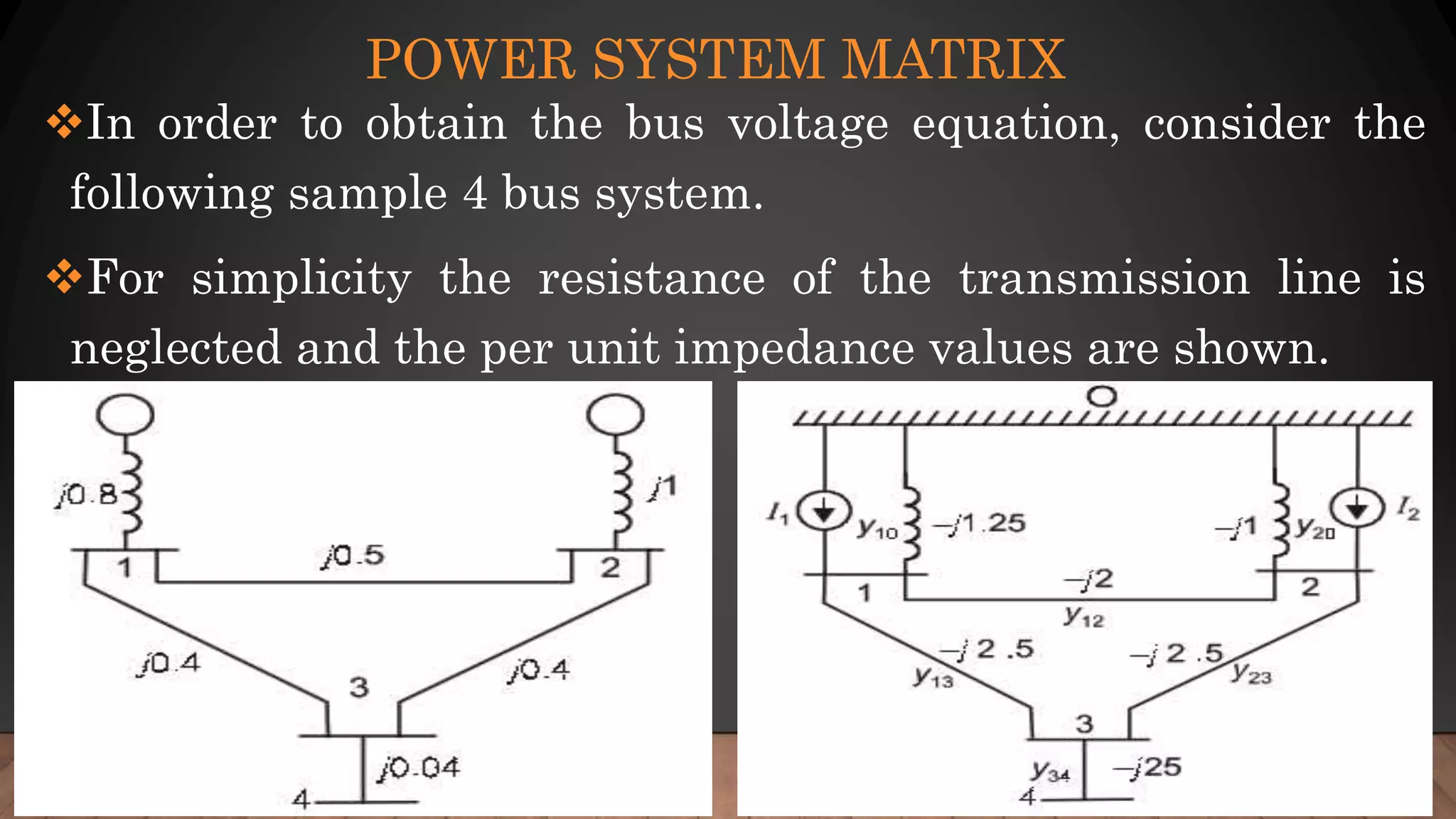
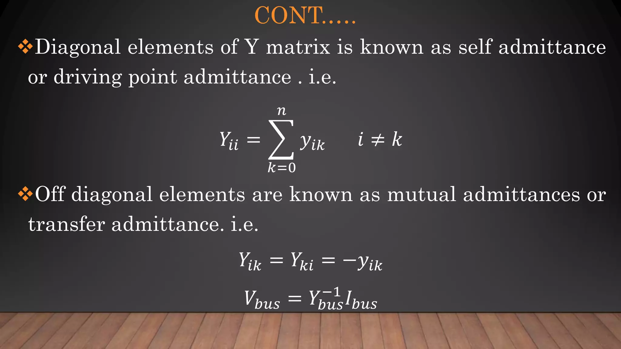
ASTU
SCHOOL OF ELECTRICAL ENGINEERING AND
COMPUTING
DEPT. OF POWER AND CONTROL ENGINEERING
COMPUTER APPLICATION IN POWER SYSTEM
(PCE5307)
CHAPTER TWO
LOAD FLOWANALYSIS
BY: MESFIN M.
OUTLINE
Network Modeling
Transmission line
Transformer
Basic Nodal Method
Power System Matrix
Admittance Matrix
Impedance Matrix
Fast Decouple Power flow Method
INTRODUCTION
 Under normal conditions electrical transmission systems
operate in their steady state mode and the basic calculation
required to determine the characteristics of this state is
termed as load flow (power flow) analysis.
The objective of load flow calculation is to determine the
steady state operating characteristics of the power
generation/transmission system for a given set of bus bar
loads
CONT.…
Active power generation is normally specified according to
economic dispatch practice.
The generation voltage magnitude is maintained at a
specified level by automatic voltage regulator acting on the
excitation system of the machine.
Loads are normally specified by their constant Active and
Reactive power requirement.
NETWORK MODELING
Transmission plant components are modelled by their
equivalent circuit in terms of inductance, capacitance and
resistance.
Among the many alternatives of describing transmission
system is to comply with the Kirchhoff's laws and two
methods Mesh and nodal analysis are used.
Nodal analysis is found to be particularly suitable for
digital computer work and is almost exclusively used for
routine network calculation.
CONT.…
Advantages of nodal analysis
Numbering of node is very simple,
Data preparation is easy
No. of variables and equations is less than mesh
Node voltage and current are easily calculated
Parallel branches doesn’t increase no. of
variable/equations
TRANSMISSION LINE MODELING
The total resistance and inductive reactance of the line
is included in series arm of the equivalent p model and
the total capacitance to the neutral is divided between
its shunt arms.
TRANSFORMER ON NOMINAL RATIO
MODELING
The p model of a transformer is illustrated below,
The impedance parameters are obtained from the open and
short circuit test of a transformer
BASIC NODAL METHOD
 In the nodal method as applied to power system; the variables are
the complex node (busbar) voltages and currents, for which some
reference must be designated.
Two different refences are normally chosen; for voltage magnitude
the reference is the ground and for the angle the reference is chosen
as the busbar voltage angle which is fixed at zero.
In the nodal method it is convenient to use branch admittance rather
than impedance.
CONT.…
By KCL, for a given node the injected current must be
equal to the sum of the currents leaving the node.
In a power system there are three kinds bus corresponding
to the known variables, this are
Generator bus (PV bus):
Load Bus (PQ bus):
Slack (Swing bus): in power system the slack bus is the
generating station which has the responsibility of system
frequency control.
CONT.….
 When node currents are specified, the set of linear equations can be
solved for the node equation.
However in power system the power are known rather than the
current, thus, resulting equation is in terms of power, known as
power flow equation. It is nonlinear and must be solved by iterative
method.
Power flow is back bone of power system analysis and design. They
are necessary for planning, operation, economic scheduling and
power exchange between utilities.
POWER SYSTEM MATRIX
In order to obtain the bus voltage equation, consider the
following sample 4 bus system.
For simplicity the resistance of the transmission line is
neglected and the per unit impedance values are shown.
CONT.….
Applying KCL at each node of the test system we can
develop the following admittance matrix.
𝐼1
𝐼2
𝐼3
𝐼4
=
𝑌11 𝑌12 𝑌13 𝑌14
𝑌21 𝑌22 𝑌23 𝑌24
𝑌31
𝑌41
𝑌32
𝑌42
𝑌33
𝑌43
𝑌34
𝑌44
.
𝑉1
𝑉2
𝑉3
𝑉4
In general
𝐼 𝑏𝑢𝑠 = 𝑌𝑏𝑢𝑠 𝑉𝑏𝑢𝑠
CONT.….
Diagonal elements of Y matrix is known as self admittance
or driving point admittance . i.e.
𝑌𝑖𝑖 =
𝑘=0
𝑛
𝑦𝑖𝑘 𝑖 ≠ 𝑘
Off diagonal elements are known as mutual admittances or
transfer admittance. i.e.
𝑌𝑖𝑘 = 𝑌𝑘𝑖 = −𝑦𝑖𝑘
𝑉𝑏𝑢𝑠 = 𝑌𝑏𝑢𝑠
−1
𝐼 𝑏𝑢𝑠
DECOUPLE METHOD
Transmission lines of a power systems have a very low R/X ratio.
For such system, real power mismatch DP are less sensitive to
changes in voltage magnitude and are very sensitive to changes in
phase angle Dd.
Similarly, reactive power mismatch DQ is less sensitive to changes
in angle and are very much sensitive on changes in voltage
magnitude.
Thus, the Jacobian matrix elements J2 and J3 are set to zero.
CONT.….
Thus,
∆𝑃
∆𝑄
=
𝐽1 0
0 𝐽4
∆𝛿
∆𝑉
Or
∆𝑃 = 𝐽1∆𝛿
∆Q = 𝐽4∆𝑉
CONT.….
Thus, For Diagonal elements of J1 are
𝜕𝑃𝑖
𝜕𝛿𝑖
=
𝑘=1
𝑘≠𝑖
𝑛
𝑉𝑖 𝑉𝑘 𝑌𝑖𝑘 sin(𝜃𝑖𝑘 − 𝛿𝑖 + 𝛿 𝑘)
For off diagonal elements of J1
𝜕𝑃𝑖
𝜕𝛿 𝑘
= − 𝑉𝑖 𝑉𝑘 𝑌𝑖𝑘 sin(𝜃𝑖𝑘 − 𝛿𝑖 + 𝛿 𝑘) 𝑘≠𝑖
CONT.….
Thus, For Diagonal elements of J4 are
𝜕𝑄𝑖
𝜕 𝑉𝑖
= −2 𝑉𝑖 𝑌𝑖𝑘 sin 𝜃𝑖𝑖 −
𝑘=1
𝑘≠𝑖
𝑛
𝑉𝑘 𝑌𝑖𝑘 sin(𝜃𝑖𝑘 − 𝛿𝑖 + 𝛿 𝑘)
For off diagonal elements of J4
𝜕𝑄𝑖
𝜕 𝑉𝑘
= − 𝑉𝑖 𝑌𝑖𝑘 sin(𝜃𝑖𝑘 − 𝛿𝑖 + 𝛿 𝑘) 𝑘≠𝑖
CONT.….
Thus, For Diagonal elements of J4 are
𝜕𝑄𝑖
𝜕 𝑉𝑖
= −2 𝑉𝑖 𝑌𝑖𝑘 sin 𝜃𝑖𝑖 −
𝑘=1
𝑘≠𝑖
𝑛
𝑉𝑘 𝑌𝑖𝑘 sin(𝜃𝑖𝑘 − 𝛿𝑖 + 𝛿 𝑘)
For off diagonal elements of J4
𝜕𝑄𝑖
𝜕 𝑉𝑘
= − 𝑉𝑖 𝑌𝑖𝑘 sin(𝜃𝑖𝑘 − 𝛿𝑖 + 𝛿 𝑘) 𝑘≠𝑖

Computer Application in Power system: Chapter two - load flow analysis

  • 1.
    ASTU SCHOOL OF ELECTRICALENGINEERING AND COMPUTING DEPT. OF POWER AND CONTROL ENGINEERING COMPUTER APPLICATION IN POWER SYSTEM (PCE5307) CHAPTER TWO LOAD FLOWANALYSIS BY: MESFIN M.
  • 2.
    OUTLINE Network Modeling Transmission line Transformer BasicNodal Method Power System Matrix Admittance Matrix Impedance Matrix Fast Decouple Power flow Method
  • 3.
    INTRODUCTION  Under normalconditions electrical transmission systems operate in their steady state mode and the basic calculation required to determine the characteristics of this state is termed as load flow (power flow) analysis. The objective of load flow calculation is to determine the steady state operating characteristics of the power generation/transmission system for a given set of bus bar loads
  • 4.
    CONT.… Active power generationis normally specified according to economic dispatch practice. The generation voltage magnitude is maintained at a specified level by automatic voltage regulator acting on the excitation system of the machine. Loads are normally specified by their constant Active and Reactive power requirement.
  • 5.
    NETWORK MODELING Transmission plantcomponents are modelled by their equivalent circuit in terms of inductance, capacitance and resistance. Among the many alternatives of describing transmission system is to comply with the Kirchhoff's laws and two methods Mesh and nodal analysis are used. Nodal analysis is found to be particularly suitable for digital computer work and is almost exclusively used for routine network calculation.
  • 6.
    CONT.… Advantages of nodalanalysis Numbering of node is very simple, Data preparation is easy No. of variables and equations is less than mesh Node voltage and current are easily calculated Parallel branches doesn’t increase no. of variable/equations
  • 7.
    TRANSMISSION LINE MODELING Thetotal resistance and inductive reactance of the line is included in series arm of the equivalent p model and the total capacitance to the neutral is divided between its shunt arms.
  • 8.
    TRANSFORMER ON NOMINALRATIO MODELING The p model of a transformer is illustrated below, The impedance parameters are obtained from the open and short circuit test of a transformer
  • 9.
    BASIC NODAL METHOD In the nodal method as applied to power system; the variables are the complex node (busbar) voltages and currents, for which some reference must be designated. Two different refences are normally chosen; for voltage magnitude the reference is the ground and for the angle the reference is chosen as the busbar voltage angle which is fixed at zero. In the nodal method it is convenient to use branch admittance rather than impedance.
  • 10.
    CONT.… By KCL, fora given node the injected current must be equal to the sum of the currents leaving the node. In a power system there are three kinds bus corresponding to the known variables, this are Generator bus (PV bus): Load Bus (PQ bus): Slack (Swing bus): in power system the slack bus is the generating station which has the responsibility of system frequency control.
  • 11.
    CONT.….  When nodecurrents are specified, the set of linear equations can be solved for the node equation. However in power system the power are known rather than the current, thus, resulting equation is in terms of power, known as power flow equation. It is nonlinear and must be solved by iterative method. Power flow is back bone of power system analysis and design. They are necessary for planning, operation, economic scheduling and power exchange between utilities.
  • 12.
    POWER SYSTEM MATRIX Inorder to obtain the bus voltage equation, consider the following sample 4 bus system. For simplicity the resistance of the transmission line is neglected and the per unit impedance values are shown.
  • 13.
    CONT.…. Applying KCL ateach node of the test system we can develop the following admittance matrix. 𝐼1 𝐼2 𝐼3 𝐼4 = 𝑌11 𝑌12 𝑌13 𝑌14 𝑌21 𝑌22 𝑌23 𝑌24 𝑌31 𝑌41 𝑌32 𝑌42 𝑌33 𝑌43 𝑌34 𝑌44 . 𝑉1 𝑉2 𝑉3 𝑉4 In general 𝐼 𝑏𝑢𝑠 = 𝑌𝑏𝑢𝑠 𝑉𝑏𝑢𝑠
  • 14.
    CONT.…. Diagonal elements ofY matrix is known as self admittance or driving point admittance . i.e. 𝑌𝑖𝑖 = 𝑘=0 𝑛 𝑦𝑖𝑘 𝑖 ≠ 𝑘 Off diagonal elements are known as mutual admittances or transfer admittance. i.e. 𝑌𝑖𝑘 = 𝑌𝑘𝑖 = −𝑦𝑖𝑘 𝑉𝑏𝑢𝑠 = 𝑌𝑏𝑢𝑠 −1 𝐼 𝑏𝑢𝑠
  • 15.
    DECOUPLE METHOD Transmission linesof a power systems have a very low R/X ratio. For such system, real power mismatch DP are less sensitive to changes in voltage magnitude and are very sensitive to changes in phase angle Dd. Similarly, reactive power mismatch DQ is less sensitive to changes in angle and are very much sensitive on changes in voltage magnitude. Thus, the Jacobian matrix elements J2 and J3 are set to zero.
  • 16.
  • 17.
    CONT.…. Thus, For Diagonalelements of J1 are 𝜕𝑃𝑖 𝜕𝛿𝑖 = 𝑘=1 𝑘≠𝑖 𝑛 𝑉𝑖 𝑉𝑘 𝑌𝑖𝑘 sin(𝜃𝑖𝑘 − 𝛿𝑖 + 𝛿 𝑘) For off diagonal elements of J1 𝜕𝑃𝑖 𝜕𝛿 𝑘 = − 𝑉𝑖 𝑉𝑘 𝑌𝑖𝑘 sin(𝜃𝑖𝑘 − 𝛿𝑖 + 𝛿 𝑘) 𝑘≠𝑖
  • 18.
    CONT.…. Thus, For Diagonalelements of J4 are 𝜕𝑄𝑖 𝜕 𝑉𝑖 = −2 𝑉𝑖 𝑌𝑖𝑘 sin 𝜃𝑖𝑖 − 𝑘=1 𝑘≠𝑖 𝑛 𝑉𝑘 𝑌𝑖𝑘 sin(𝜃𝑖𝑘 − 𝛿𝑖 + 𝛿 𝑘) For off diagonal elements of J4 𝜕𝑄𝑖 𝜕 𝑉𝑘 = − 𝑉𝑖 𝑌𝑖𝑘 sin(𝜃𝑖𝑘 − 𝛿𝑖 + 𝛿 𝑘) 𝑘≠𝑖
  • 19.
    CONT.…. Thus, For Diagonalelements of J4 are 𝜕𝑄𝑖 𝜕 𝑉𝑖 = −2 𝑉𝑖 𝑌𝑖𝑘 sin 𝜃𝑖𝑖 − 𝑘=1 𝑘≠𝑖 𝑛 𝑉𝑘 𝑌𝑖𝑘 sin(𝜃𝑖𝑘 − 𝛿𝑖 + 𝛿 𝑘) For off diagonal elements of J4 𝜕𝑄𝑖 𝜕 𝑉𝑘 = − 𝑉𝑖 𝑌𝑖𝑘 sin(𝜃𝑖𝑘 − 𝛿𝑖 + 𝛿 𝑘) 𝑘≠𝑖