Download to read offline
![IOSR Journal of Electrical and Electronics Engineering (IOSR-JEEE)
e-ISSN: 2278-1676,p-ISSN: 2320-3331, Volume 10, Issue 2 Ver. II (Mar – Apr. 2015), PP 31-39
www.iosrjournals.org
DOI: 10.9790/1676-10223139 www.iosrjournals.org 31 | Page
Power Flow Control of STATCOM and UPFC in Distribution
System
S. Saravana Kumar*, S. Sankar **, M. Padmarasan ***, C. T. Mani Kandan
****Professor, Dept of IT,Panimalar Institute of Technology, Chennai,
** Professor, Dept of EEE,Panimalar Institute of Technology, Chennai,
***Assistant Professor(G-I), Dept of EEE,Panimalar Institute of Technology, Chennai.
Abstract: This paper not only describes the closed loop reactive power control design procedure but also
deals with the study on the application of the Static VAR Compensator for the control of such power in
distribution system. Furthermore, the dynamic behavior of the system is analyzed in this paper the
operating circuit model of VAR Compensator and Unified Power flow Controller were simulated. The
simulation results agree with the theoretical results. This simulation tests under various transient conditions
are analyzed this results obtained may lead to correct design of a robust controller for reactive power
applications.
Index Terms: FACTS controllers, FACTS, power electronic equipment, Control, PWM
I. Introduction
Improved utilization of the existing power system is provided through the application of advanced
control technologies. Power electronics based equipment, or Flexible AC Transmission Systems (FACTS),
provide proven technical solutions to address these new operating challenges being presented today. FACTS
technologies allow for improved transmission system operation with minimal infrastructure investment,
environmental impact, and implementation time compared to the construction of new transmission
lines. Traditional solutions to upgrading the electrical transmission system infrastructure have been primarily
in the form of new transmission lines, substations, and associated equipment.
However, as experiences have proven over the past decade or more, the process to permit, site, and
construct new transmission lines has become extremely difficult, expensive, time-consuming, and
controversial. FACTS technologies provide advanced solutions as cost-effective alternatives to new
transmission line construction. The potential benefits of FACTS equipment are now widely recognized by the
power systems engineering and T&D communities.
With respect to FACTS equipment, voltage sourced
converter (VSC) technology, which utilizes self commutatedthyristors and various transistors such as GTOs, G
CTs, IGCTs,and IGBTs, has been successfully applied in a number of inst
allations world wide for static synchronous compensators[1-5], Unified Power Flow Controllers (UPFC) [6,
7],
Convertible Series Compensators (CSC) [8], back-to-back dc ties (VSC-BTB) [9, 10] and VSC transmission
[11].
II. Mathematical Model Of The SVC
In the Fig.1 shows a simplified equivalent circuit of the SVC [12]. Using matrix form, the mathematical model
is given by
cc
bb
aa
c
b
a
b
a
ev
ev
ev
Li
i
i
L
R
L
R
L
R
ic
i
i
dt
d 1
00
00
00
(1)
The model of the inverter output voltage is given by](https://image.slidesharecdn.com/d010223139-160705060521/85/D010223139-1-320.jpg)
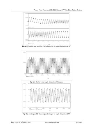
![Power Flow Control of STATCOM and UPFC in Distribution System
DOI: 10.9790/1676-10223139 www.iosrjournals.org 33 | Page
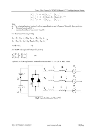
III. Series Compensator
Fig.2 represents the SVC connected to Network bus for regulating the local load reactive power.
Control
Block
~
C
C
10 MW
8 MVAR+-
Fig.2. STATCOM connected to the network
The control of the SVC was designed to compensate the reactive power of the local load.
To achieve a simple design of the control, equations depicted above must be transformed in d-q Frame
and linearized under the following assumptions [6].
Disturbance is small
The second-order terms are dropped
The quiescent operating o is near zero
The annotation is introduced to indicate the perturbed values.
We obtain equation (6) in state space form
0
0
1
020
0 L
co
do
qo
co
do
qo V
L
U
i
i
CD
LDLR
LR
U
i
i
dt
d
(6)
co
do
qo
L
U
i
i
VQc 00
Small signal equivalent model system is used to calculate the transfer function of the system equation (7).
)(
)(
)(
)(
)(
sB
sA
s
sQ
sG C
(7)
LC
D
s
L
R
s
L
V
sA L
2
)(
2
2
2
CL
RD
s
LC
D
L
R
s
L
R
ssB 2
2
2
22
23
22
2
)(
](https://image.slidesharecdn.com/d010223139-160705060521/85/D010223139-3-320.jpg)

![Power Flow Control of STATCOM and UPFC in Distribution System
DOI: 10.9790/1676-10223139 www.iosrjournals.org 38 | Page
In equation (13), the term Qconv1 which is equal to
B
conv
iconv
S
S
VI q
1
1 enables variable Iconv1q to be set as
parameter. This formulation of the model makes the computation of the sensitivities easy to be implemented in
straight forward manner.
The total active power loss is formulated as
n
m
n
k
mkmkkmloss GVVVP
1 1
cos, (15)
Since the loss minimization is of concern, the sensitivity is to be computed. Change in the loss ∆Ploss is
expressed as
p
p
P
y
y
P
x
x
P
pyxP losslossloss
loss
,, (16)
From equation (9), changes ∆x and ∆y with respect to ∆p are
pgfggfAggy
pfggfAx
pppyysxy
ppyys
111
11
(17)
Since the partial derivatives are as follows
and
p
P
x
P lossloss
0;0
(18)
Then the sensitivity
dp
dPloss
is finally expressed as
pppyysxy
lossloss
gfggfAgg
y
P
dP
dP
111
(19)
In this formulation fp = 0, enabling some more simplification, where gp is a three column matrix (gr ,
gγ , gIconv1q) simply obtained by differentiating network equations (11) to (13) with respect to the UPFC’s set of
control parameters (r, γ, Iconv1q).
VI. Conclusion
In this paper STATCOM and Unified Power flow Controller circuits were successfully simulated. It
is shown that, the power transmitted increases as the number of capacitors increases. Unified power flow
controller is simulated for different phase angles of midpoint source. From the results of the simulations and
the mathematical modelling developed in this paper.
References
[1]. S. Mori, K. Matsuno, T. Hasegawa, S. Ohnishi, M. Takeda, M. Seto, S. Murakami, F. Ishiguro, “Development of a Large Static
VAR Generator Using Self-Commutated Inverters for Improving Power System Stability,” IEEE Transactions on Power Systems, Vol.
8, No. 1, February,2013, pp. 371-377.
[2]. M.Hirakawa, H. Somiya, Y. Mino, K. Baba, S. Murakami, Y. Watanabe, “Application of Self-Commutated Inverters to Substation
Reactive Power Control,” CIGRE Paper 23-205, Paris Session, 2012.
[3]. C. Schauder, M. Gernhardt, E. Stacey, T. Lemak, L. Gyugyi, T.W. Cease, A. Edris, M. Wilhelm, “TVA STATCOM Project: Design,
Installation, and Commissioning,” CIGRE Paper 14-106, Paris General Session, 2013.
[4]. C. Schauder, “STATCOM for Compensation of Large Electric Arc Furnace Installations,” Proceedings of the IEEE PES Summer
Power Meeting, Edmonton, Alberta, July 2013, pp. 1109-1112.
n
k
mkmkk
m
loss
n
mk
k
mkmkkm
m
loss
loss
GV
V
P
GVV
P
y
P
1
1
cos2
sin2
](https://image.slidesharecdn.com/d010223139-160705060521/85/D010223139-8-320.jpg)
![Power Flow Control of STATCOM and UPFC in Distribution System
DOI: 10.9790/1676-10223139 www.iosrjournals.org 39 | Page
[5]. D.J. Hanson, C. Horwill, B.D. Gemmell, D.R. Monkhouse, “A STATCOM- Based Relocatable SVC Project in the UK for National
Grid,” Proceedings of the IEEE PES Winter Power Meeting, New York, January 2012.
[6]. C. Schauder, E. Stacey, M. Lund, L. Gyugyi, L. Kovalsky, A. Keri, A. Mehraban, A. Edris, "AEP UPFC Project: Installation,
Commissioning and Operation of The ±160 MVA STATCOM(Phase I)," IEEE Transactions on Power Delivery Vol. 13, No. 4,
October 2012, pp. 1530- 1535.
[7]. B.A. Renz, A.J.F. Keri, A.S. Mehraban, J.P. Kessinger, C.D. Schauder, L. Gyugyi, L.J. Kovalsky, A.A. Edris, “World’s First Unified
Power Flow Controller on the AEP System,” CIGRE Paper 14-107, Paris Session, 2013.
[8]. B. Fardanesh, M. Henderson, B. Shperling, S. Zelingher, L. Gyugyi, C. Schauder, B. Lam, J. Mountford, R. Adapa, A. Edris,
“Convertible Static Compensator Application to the New York Transmission System,” CIGRE Paper 14-103, Paris Session, 2013.
[9]. H. Suzuki, M. Takeda, G. Reed, “Application of Voltage Source Converter Technology to a Back-to-Back DC Link,” Presented at
the Panel Session on FACTS Controllers: Applications and Operational Experience, Proceedings of the IEEE PES Summer Power
Meeting, Edmonton, Alberta, July 2009.
[10]. T. Larsson A. Edris, D. Kidd, F. Aboytes, “Eagle Pass Back-to-Back Tie: a Dual Purpose Application of Voltage Source Converter
Technology,” Proceedings of the 2001 IEEE PES Summer Power Meeting, Vancouver, BC, July 2008.
[11]. G.Aspland, K. Eriksson, O. Tollerz, “HVDC Light, A Tool for Electric Power Transmission to Distant Loads,” VI SEPOPE
Conference, Salvador, Brazil, May, 2008.
[12]. N.G. Hingorani, “Introducing Custom Power,” IEEE Spectrum, June 2009.](https://image.slidesharecdn.com/d010223139-160705060521/85/D010223139-9-320.jpg)

This document summarizes a study on using STATCOM and UPFC devices to control power flow in a distribution system. It presents the mathematical models of STATCOM and UPFC, including their control design procedures. Simulation results show that STATCOM effectively regulates local reactive power load and UPFC controls real power flow by varying the phase angle of injected voltage. The study demonstrates how FACTS devices like STATCOM and UPFC can improve power flow control in distribution systems.


![6.[36 45]seven level modified cascaded inverter for induction motor drive app...](https://cdn.slidesharecdn.com/ss_thumbnails/6-36-45sevenlevelmodifiedcascadedinverterforinductionmotordriveapplications-111118181646-phpapp02-thumbnail.jpg?width=640&height=640&fit=bounds)