Downloaded 984 times
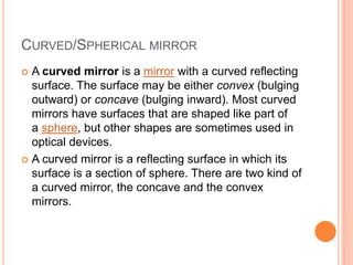
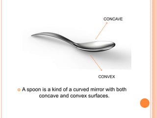

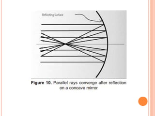
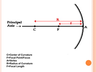
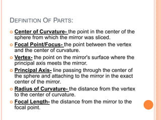
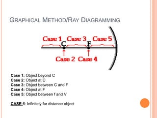
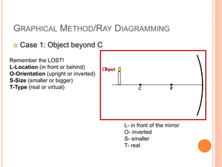
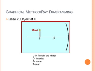
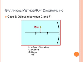
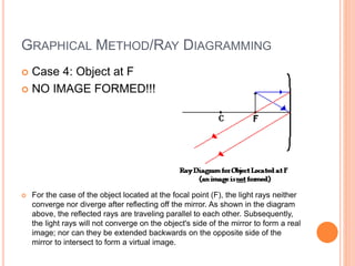
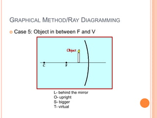

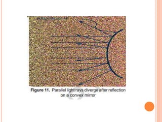
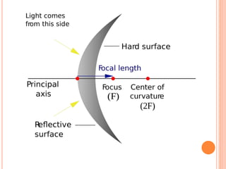
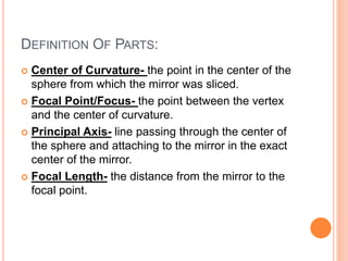
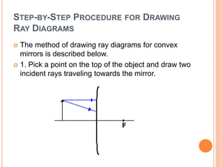
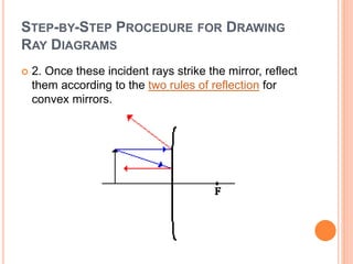
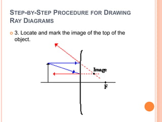
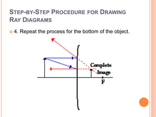

This document discusses curved mirrors, including concave and convex mirrors. It defines key terms like center of curvature, focal point, vertex, radius of curvature, and focal length. The document explains that concave mirrors form real, inverted images between the focal point and center of curvature, and virtual, upright images beyond the focal point. Convex mirrors always form virtual, upright images that are smaller than the object. Diagrams demonstrate the ray tracing method for different object positions with concave and convex mirrors.


![Lens and Mirrors [Autosaved] for Grade 10.pptx](https://cdn.slidesharecdn.com/ss_thumbnails/lensandmirrorsautosaved-240111005021-d88c59fc-thumbnail.jpg?width=640&height=640&fit=bounds)


