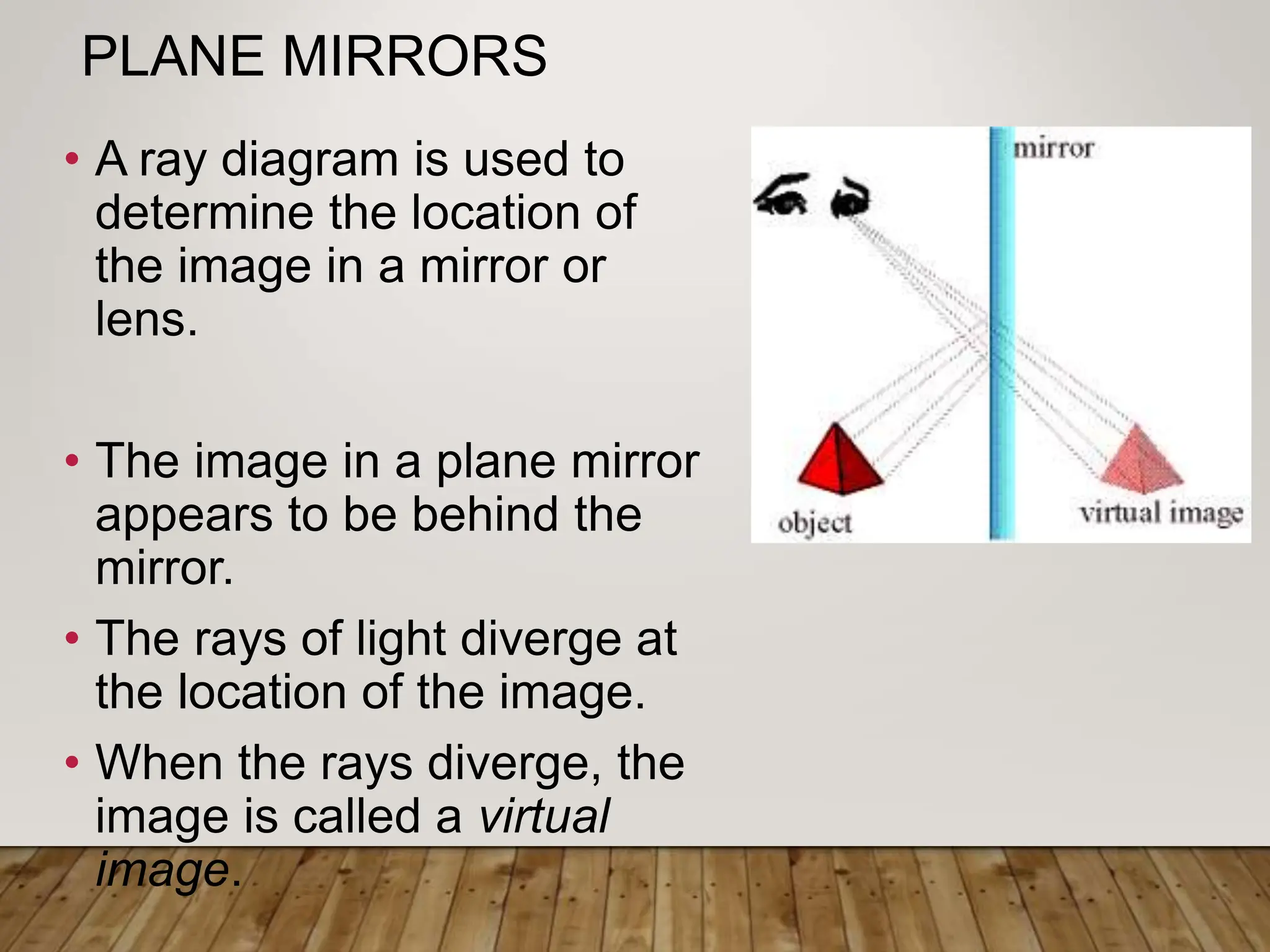
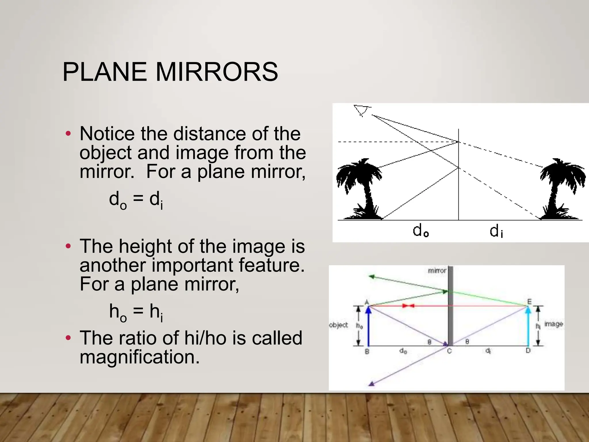
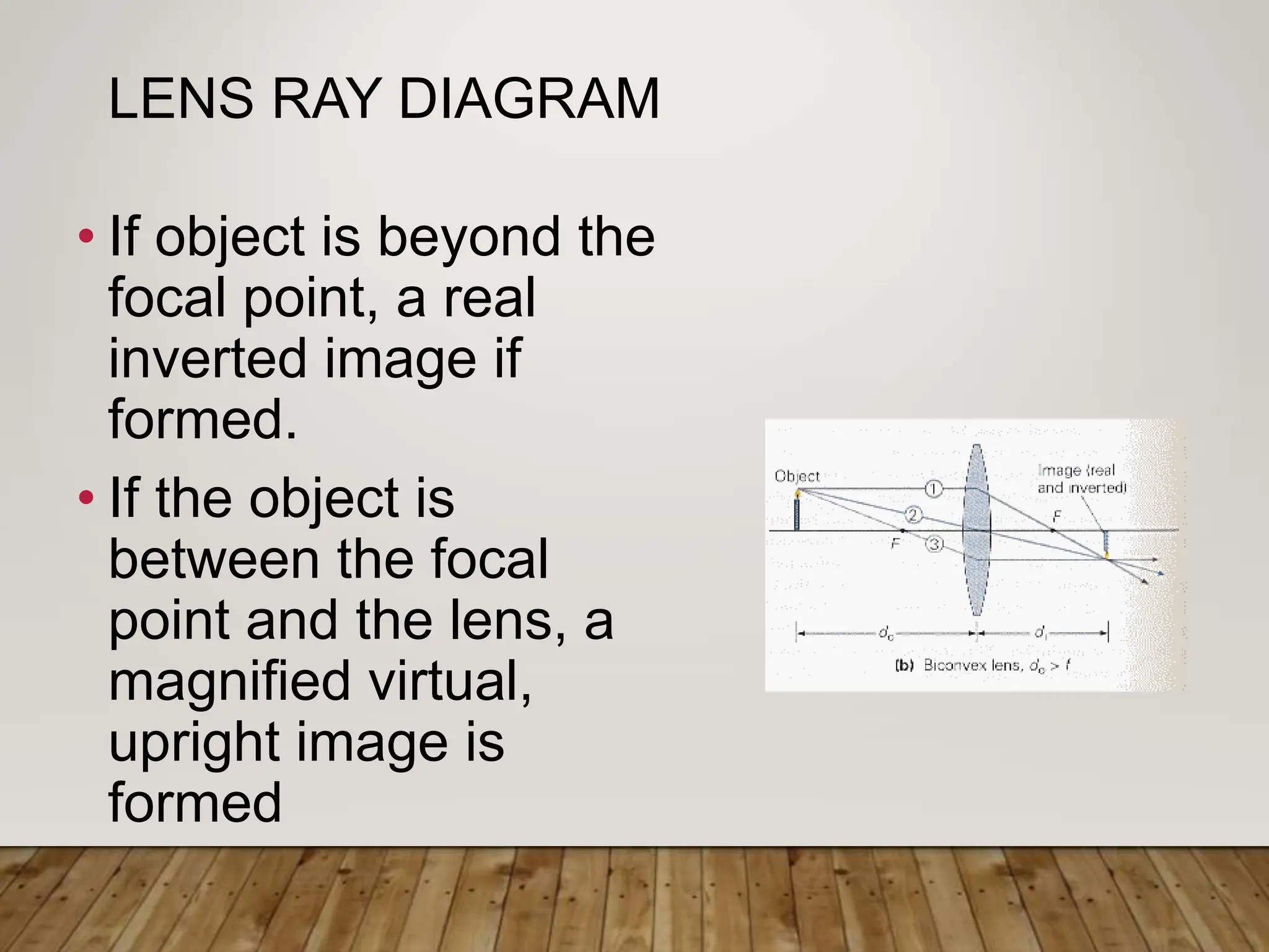
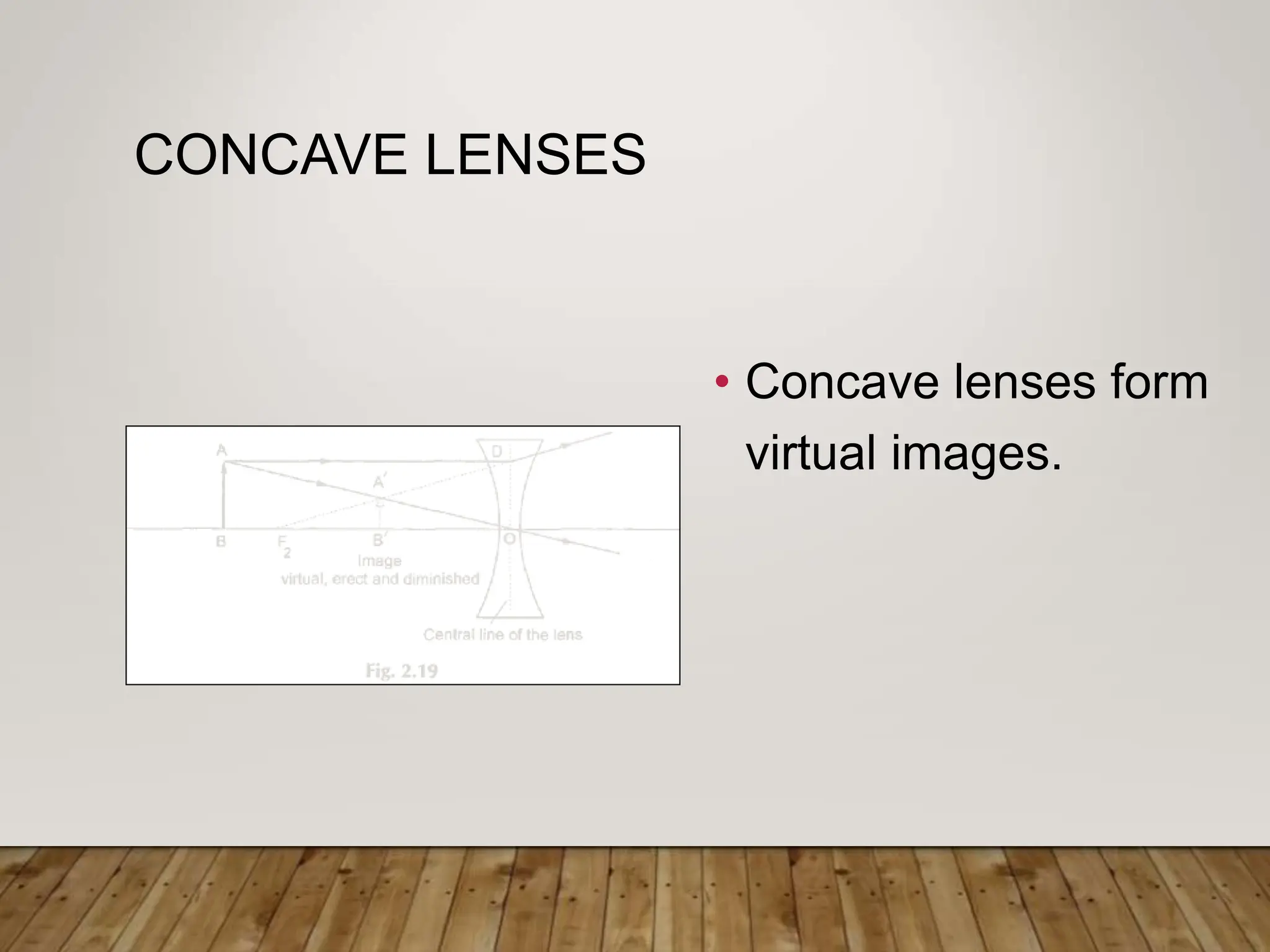
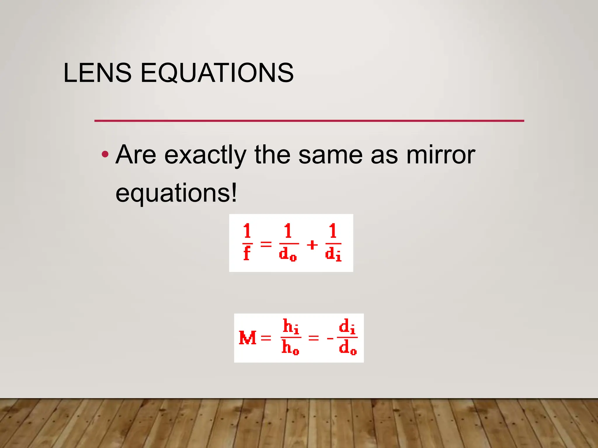
MIRRORS AND
LENSES
PREPARED BY: TYPE YOUR NAME HERE
MIRRORS
• Mirrors form images using the property of light
called reflection, unlike lenses which form
images using refraction.
• Mirrors are smooth reflecting surfaces.
• A plane mirror is a flat surface. Usually it is
glass coated with a reflective metallic
substance.
PLANE MIRRORS
• A ray diagram is used to
determine the location of
the image in a mirror or
lens.
• The image in a plane mirror
appears to be behind the
mirror.
• The rays of light diverge at
the location of the image.
• When the rays diverge, the
image is called a virtual
image.
PLANE MIRRORS
• Notice the distance of the
object and image from the
mirror. For a plane mirror,
do = di
• The height of the image is
another important feature.
For a plane mirror,
ho = hi
• The ratio of hi/ho is called
magnification.
PLANE MIRRORS
• Plane mirrors form virtual images.
• Image distance is equal to object
distance. do = di
• Magnification = 1
EXAMPLE
•What is the minimum vertical
length of a plane mirror
needed for a person to see a
complete head to toe image of
himself?
SPHERICAL MIRRORS
•Spherical mirrors are reflecting
surfaces with spherical
geometry.
•For reflections on the inside
surface, the mirror is called
concave.
•For reflections on the outside
surface, the mirror is called
convex.
CONCAVE MIRRORS
• Concave mirrors focus
light at a single point.
• Light rays that travel
parallel to the mirror
reflect through the focal
point.
• The focal point is half of
the radius of curvature.
• Since light rays converge,
the image formed is real.
You could project an
image on a carefully
placed card.
CONCAVE MIRRORS – RAY
DIAGRAMS
• Optical Axis - a line through the center of
the mirror that intersects the surface of
the mirror.
• Center of Curvature – center of the circle
• Focal point – the point at which reflected
rays intersect
RAY DIAGRAMS
• Draw the mirror, the optical axis, the center of
curvature,and the focal point.
• Draw the object at the appropriate position.
1. Draw the first ray from the object to the mirror parallel to
the optical axis, and reflecting through the focal point.
2. Draw the second ray through the center of curvature.
3. A third ray travels from the object through the focal point
and to the mirror. It reflects parallel to the mirror.
• An image will be formed where the rays converge.
CONCAVE MIRROR RAY DIAGRAM
•Notice the object is
placed beyond C.
•Three rays are
drawn.
•The image is real,
inverted, located
between C and F,
and reduced.
CONCAVE MIRRORS – THREE
SITUATIONS
• If do >C, then f<di<C
and is real, reduced,
inverted.
• If f<do<C, then di>C
and is real, inverted,
and enlarged. (no
picture)
• If do <f, then image is
virtual and enlarged.
MIRROR EQUATIONS
• The image and object distances are related by
• The magnification can be found using
SIGN CONVENTIONS FOR
SPHERICAL MIRRORS
EXAMPLE
•A concave mirror has a radius
of curvature of 30cm. If an
object is placed a)45cm b) 20
cm c) 10 cm from the mirror,
where is the image formed
and what are its
characteristics?
EXAMPLE
• An object is placed 20cm in front
of a diverging mirror that has a
focal length of -15cm. Use a ray
diagram to determine whether the
image formed is real or virtual.
Find the location of the image
using equations.
SPHERICAL ABERRATIONS
• Spherical mirrors
focus light well for
small angles of
incidence (and
reflection) but
produce blurry images
for larger angles of
incidence.
• Parabolic mirrors
focus parallel rays
from distant objects at
one focal point.
LENSES
• Lenses focus light by refracting light to
form an image.
• Biconvex lenses are convex on both
surfaces and cause rays to converge.
• Biconcave lenses are concave on both
surfaces and cause light to diverge.
LENSES
THREE RAYS TO DRAW!
• First ray: parallel to optical axis and
refracting through focal point.
• Second ray: called the chief ray passes
from the object through the center of the
lens un-refracted.
• Third ray: through the focal point and
refracting parallel to optical axis.
LENS RAY DIAGRAM
• If object is beyond the
focal point, a real
inverted image if
formed.
• If the object is
between the focal
point and the lens, a
magnified virtual,
upright image is
formed
CONCAVE LENSES
• Concave lenses form
virtual images.
LENS EQUATIONS
• Are exactly the same as mirror
equations!
EXAMPLE
• An object is 30 cm in front of a
biconvex lens of focal length 20
cm. Use a ray diagram to locate
the image. Discuss the
characteristics of the image.
HOMEWORK
• Pg 755 # 45, 49, 54, 55, 59, 62,
63, 69 – 71, 75
• Begin to prepare for Ch 22,23
exam on MONDAY.
COMBINATIONS OF LENSES
• The image of the first lens becomes the object
of the second lens!
• If the image of the first lens is on the opposite
side of the second lens, consider the image of
the first lens to be a virtual object for the
second lens and do becomes negative.
• Magnification of the total Mtot = M1M2
EXAMPLE
• Consider two lenses similar to those
illustrated in fig 23.19. Suppose the
object is 20 cm in front of lens L1
which has focal length of 15 cm. Lens
L2, with focal length of 12 cm, is 26 cm
from L1. What is the location of the
final image?
CONTENT, IMAGES, TEXT, ETC. USED BELONG TO THE RIGHTFUL
OWNER. NO COPYRIGHT INFRINGEMENT INTENDED.

G10 Science Q2-Week 8- Properties of Mirror.ppt

  • 1.
  • 2.
    MIRRORS • Mirrors formimages using the property of light called reflection, unlike lenses which form images using refraction. • Mirrors are smooth reflecting surfaces. • A plane mirror is a flat surface. Usually it is glass coated with a reflective metallic substance.
  • 3.
    PLANE MIRRORS • Aray diagram is used to determine the location of the image in a mirror or lens. • The image in a plane mirror appears to be behind the mirror. • The rays of light diverge at the location of the image. • When the rays diverge, the image is called a virtual image.
  • 4.
    PLANE MIRRORS • Noticethe distance of the object and image from the mirror. For a plane mirror, do = di • The height of the image is another important feature. For a plane mirror, ho = hi • The ratio of hi/ho is called magnification.
  • 5.
    PLANE MIRRORS • Planemirrors form virtual images. • Image distance is equal to object distance. do = di • Magnification = 1
  • 6.
    EXAMPLE •What is theminimum vertical length of a plane mirror needed for a person to see a complete head to toe image of himself?
  • 7.
    SPHERICAL MIRRORS •Spherical mirrorsare reflecting surfaces with spherical geometry. •For reflections on the inside surface, the mirror is called concave. •For reflections on the outside surface, the mirror is called convex.
  • 8.
    CONCAVE MIRRORS • Concavemirrors focus light at a single point. • Light rays that travel parallel to the mirror reflect through the focal point. • The focal point is half of the radius of curvature. • Since light rays converge, the image formed is real. You could project an image on a carefully placed card.
  • 9.
    CONCAVE MIRRORS –RAY DIAGRAMS • Optical Axis - a line through the center of the mirror that intersects the surface of the mirror. • Center of Curvature – center of the circle • Focal point – the point at which reflected rays intersect
  • 10.
    RAY DIAGRAMS • Drawthe mirror, the optical axis, the center of curvature,and the focal point. • Draw the object at the appropriate position. 1. Draw the first ray from the object to the mirror parallel to the optical axis, and reflecting through the focal point. 2. Draw the second ray through the center of curvature. 3. A third ray travels from the object through the focal point and to the mirror. It reflects parallel to the mirror. • An image will be formed where the rays converge.
  • 11.
    CONCAVE MIRROR RAYDIAGRAM •Notice the object is placed beyond C. •Three rays are drawn. •The image is real, inverted, located between C and F, and reduced.
  • 12.
    CONCAVE MIRRORS –THREE SITUATIONS • If do >C, then f<di<C and is real, reduced, inverted. • If f<do<C, then di>C and is real, inverted, and enlarged. (no picture) • If do <f, then image is virtual and enlarged.
  • 13.
    MIRROR EQUATIONS • Theimage and object distances are related by • The magnification can be found using
  • 14.
  • 15.
    EXAMPLE •A concave mirrorhas a radius of curvature of 30cm. If an object is placed a)45cm b) 20 cm c) 10 cm from the mirror, where is the image formed and what are its characteristics?
  • 16.
    EXAMPLE • An objectis placed 20cm in front of a diverging mirror that has a focal length of -15cm. Use a ray diagram to determine whether the image formed is real or virtual. Find the location of the image using equations.
  • 17.
    SPHERICAL ABERRATIONS • Sphericalmirrors focus light well for small angles of incidence (and reflection) but produce blurry images for larger angles of incidence. • Parabolic mirrors focus parallel rays from distant objects at one focal point.
  • 18.
    LENSES • Lenses focuslight by refracting light to form an image. • Biconvex lenses are convex on both surfaces and cause rays to converge. • Biconcave lenses are concave on both surfaces and cause light to diverge.
  • 19.
  • 20.
    THREE RAYS TODRAW! • First ray: parallel to optical axis and refracting through focal point. • Second ray: called the chief ray passes from the object through the center of the lens un-refracted. • Third ray: through the focal point and refracting parallel to optical axis.
  • 21.
    LENS RAY DIAGRAM •If object is beyond the focal point, a real inverted image if formed. • If the object is between the focal point and the lens, a magnified virtual, upright image is formed
  • 22.
    CONCAVE LENSES • Concavelenses form virtual images.
  • 23.
    LENS EQUATIONS • Areexactly the same as mirror equations!
  • 24.
    EXAMPLE • An objectis 30 cm in front of a biconvex lens of focal length 20 cm. Use a ray diagram to locate the image. Discuss the characteristics of the image.
  • 25.
    HOMEWORK • Pg 755# 45, 49, 54, 55, 59, 62, 63, 69 – 71, 75 • Begin to prepare for Ch 22,23 exam on MONDAY.
  • 26.
    COMBINATIONS OF LENSES •The image of the first lens becomes the object of the second lens! • If the image of the first lens is on the opposite side of the second lens, consider the image of the first lens to be a virtual object for the second lens and do becomes negative. • Magnification of the total Mtot = M1M2
  • 28.
    EXAMPLE • Consider twolenses similar to those illustrated in fig 23.19. Suppose the object is 20 cm in front of lens L1 which has focal length of 15 cm. Lens L2, with focal length of 12 cm, is 26 cm from L1. What is the location of the final image?
  • 29.
    CONTENT, IMAGES, TEXT,ETC. USED BELONG TO THE RIGHTFUL OWNER. NO COPYRIGHT INFRINGEMENT INTENDED.