Downloaded 128 times


![Representing Objects Interested in object’s boundary (or manifold) Various approaches Procedural representations Often fractal Explicit polygon (triangle) meshes By far, the most popular method Curved surface patches Often displacement mapped Implicit representation Blobby, volumetric Sierpinski gasket Utah Teapot Blobby modeling in RenderMan Quake 2 key frame triangle meshes Fractal tree [Philip Winston]](https://image.slidesharecdn.com/07objects-120210171804-phpapp01/75/CS-354-Object-Viewing-and-Representation-34-2048.jpg)
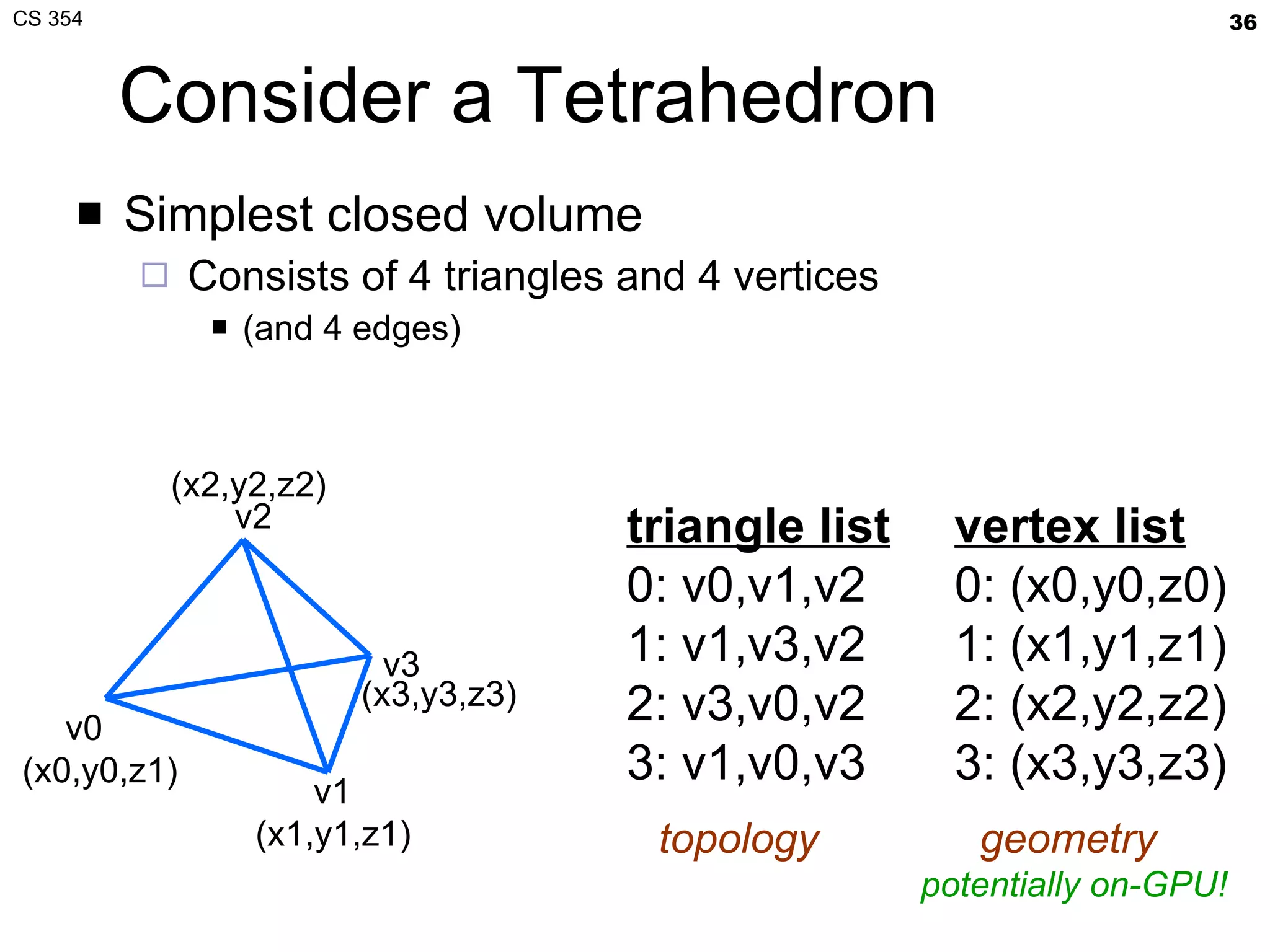


- The document summarizes a lecture on viewing and representing 3D objects in computer graphics. It discusses representing objects as triangle meshes and storing vertex data in arrays indexed by triangle lists. It also covers transforms like glFrustum and gluLookAt for viewing, and examples of modeling transforms. - Common ways to represent 3D objects include procedural, explicit polygon meshes, and implicit surfaces. Triangle meshes stored with unique vertex positions and triangle indices are popular due to efficiency and compatibility with OpenGL/GPU rendering. - The lecture also covered projection transforms, modeling transforms, lighting, and "look at" camera positioning for 3D viewing. Next lecture will discuss mesh properties and OpenGL rendering details.


![Vibe Coding vs. Spec-Driven Development [Free Meetup]](https://cdn.slidesharecdn.com/ss_thumbnails/vibecodingvsspecdrivendevelopment-251209105622-43f455e7-thumbnail.jpg?width=640&height=640&fit=bounds)


