Downloaded 81 times
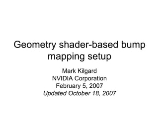


![Geometry Shader in Cg TRIANGLE void md2bump_geometry( AttribArray < float4 > position : POSITION , AttribArray < float2 > texCoord : TEXCOORD0 , AttribArray < float3 > objPosition : TEXCOORD1 , AttribArray < float3 > objNormal : TEXCOORD2 , AttribArray < float3 > objView : TEXCOORD3 , AttribArray < float3 > objLight : TEXCOORD4 ) { float3 dXYZdU = objPosition[1] - objPosition[0]; float dSdU = texCoord[1].s - texCoord[0].s; float3 dXYZdV = objPosition[2] - objPosition[0]; float dSdV = texCoord[2].s - texCoord[0].s; float3 tangent = normalize (dSdV * dXYZdU - dSdU * dXYZdV); for ( int i=0; i<3; i++) { float3 normal = objNormal[i], binormal = cross (tangent,normal); float3x3 basis = float3x3 ( tangent , binormal, normal); float3 surfaceLightVector : TEXCOORD1 = mul (basis, objLight[i]); float3 surfaceViewVector : TEXCOORD2 = mul (basis, objView[i]); emitVertex (position[i], texCoord[i], surfaceLightVector, surfaceViewVector); } } warning: not tolerant of mirroring (see next version)](https://image.slidesharecdn.com/geometryshaderbasedbumpmappingsetup-120301034520-phpapp02/85/Geometry-Shader-based-Bump-Mapping-Setup-3-320.jpg)


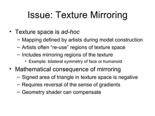

![Mirroring-tolerant Geometry Shader in Cg TRIANGLE void md2bump_geometry( AttribArray < float4 > position : POSITION , AttribArray < float2 > texCoord : TEXCOORD0 , AttribArray < float3 > objPosition : TEXCOORD1 , AttribArray < float3 > objNormal : TEXCOORD2 , AttribArray < float3 > objView : TEXCOORD3 , AttribArray < float3 > objLight : TEXCOORD4 ) { float3 dXYZdU = objPosition[1] - objPosition[0]; float dSdU = texCoord[1].s - texCoord[0].s; float3 dXYZdV = objPosition[2] - objPosition[0]; float dSdV = texCoord[2].s - texCoord[0].s; float3 tangent = normalize (dSdV * dXYZdU - dSdU * dXYZdV); float area = determinant ( float2x2 (dSTdV, dSTdU)); float3 orientedTangent = area >= 0 ? tangent : -tangent; for ( int i=0; i<3; i++) { float3 normal = objNormal[i], binormal = cross (tangent,normal); float3x3 basis = float3x3 (orientedTangent, binormal, normal); float3 surfaceLightVector : TEXCOORD1 = mul (basis, objLight[i]); float3 surfaceViewVector : TEXCOORD2 = mul (basis, objView[i]); emitVertex (position[i], texCoord[i], surfaceLightVector, surfaceViewVector); } } additional & changed code for mirroring](https://image.slidesharecdn.com/geometryshaderbasedbumpmappingsetup-120301034520-phpapp02/85/Geometry-Shader-based-Bump-Mapping-Setup-11-320.jpg)
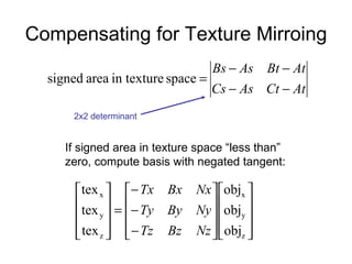
![Discarding Triangles Significantly Back Facing w.r.t. the Light TRIANGLE void md2bump_geometry( AttribArray < float4 > position : POSITION , AttribArray < float2 > texCoord : TEXCOORD0 , AttribArray < float3 > objPosition : TEXCOORD1 , AttribArray < float3 > objNormal : TEXCOORD2 , AttribArray < float3 > objView : TEXCOORD3 , AttribArray < float3 > objLight : TEXCOORD4 ) { float3 dXYZdU = objPosition[1] - objPosition[0]; float dSdU = texCoord[1].s - texCoord[0].s; float3 dXYZdV = objPosition[2] - objPosition[0]; float dSdV = texCoord[2].s - texCoord[0].s; float3 tangent = normalize (dSdV * dXYZdU - dSdU * dXYZdV); float maxLightZ, maxLightThreshold = -0.3; for ( int i=0; i<3; i++) { float3 normal = objNormal[i], binormal = cross (tangent,normal); float3x3 basis = float3x3 ( tangent , binormal, normal); float3 surfaceLightVector : TEXCOORD1 = mul (basis, objLight[i]); maxLightZ = i==0 ? normalize(surfaceLightVector).z : max(maxLightZ, normalize(surfaceLightVector).z); float3 surfaceViewVector : TEXCOORD2 = mul (basis, objView[i]); if (i < 2 || maxLightZ > maxLightThreshold) emitVertex (position[i], texCoord[i], surfaceLightVector, surfaceViewVector); } }](https://image.slidesharecdn.com/geometryshaderbasedbumpmappingsetup-120301034520-phpapp02/85/Geometry-Shader-based-Bump-Mapping-Setup-12-320.jpg)

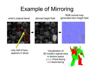
![Geometry Shader in Cg Sans Normals TRIANGLE void md2bump_geometry_sans_normal( AttribArray < float4 > position : POSITION , AttribArray < float2 > texCoord : TEXCOORD0 , AttribArray < float3 > objPosition : TEXCOORD1 , // IGNORE per-vertex normal! AttribArray < float3 > objView : TEXCOORD3 , AttribArray < float3 > objLight : TEXCOORD4 ) { float3 dXYZdU = objPosition[1] - objPosition[0]; float2 dSTdU = texCoord[1] - texCoord[0]; float3 dXYZdV = objPosition[2] - objPosition[0]; float2 dSTdV = texCoord[2] - texCoord[0]; float3 tangent = normalize (dSTdV.s * dXYZdU - dSTdU.s * dXYZdV); float3 tangent2 = normalize (dSTdV.t * dXYZdU - dSTdU.t * dXYZdV); float area = determinant (float2x2(dSTdV, dSTdU)); tangent = area >= 0 ? tangent : -tangent; float3 normal = cross(tangent2,tangent); tangent2 = area >= 0 ? tangent2 : -tangent2; for ( int i=0; i<3; i++) { float3x3 basis = float3x3 (tangent, tangent2, normal); float3 surfaceLightVector : TEXCOORD1 = mul(basis, objLight[i]); float3 surfaceViewVector : TEXCOORD2 = mul(basis, objView[i]); emitVertex (position[i], texCoord[i], surfaceLightVector, surfaceViewVector); } }](https://image.slidesharecdn.com/geometryshaderbasedbumpmappingsetup-120301034520-phpapp02/85/Geometry-Shader-based-Bump-Mapping-Setup-15-320.jpg)
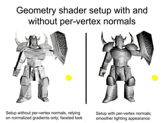


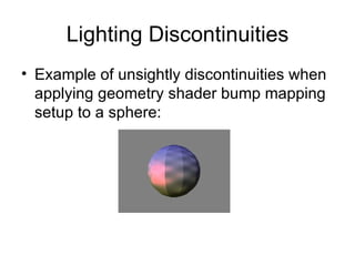


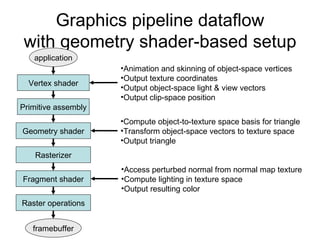
The document describes a geometry shader-based approach to bump mapping that has several advantages over traditional CPU-based approaches. The geometry shader constructs an object-to-texture space mapping for each triangle, allowing lighting computations to be done efficiently in texture space in the pixel shader. It addresses issues like texture mirroring and lighting discontinuities. Examples and Cg source code are provided to illustrate the technique.


![Class[5][9th jul] [three js-meshes_geometries_and_primitives]](https://cdn.slidesharecdn.com/ss_thumbnails/class59thjul-threejsmeshesgeometriesandprimitivestemp-210726102924-thumbnail.jpg?width=640&height=640&fit=bounds)