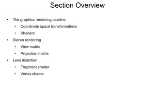
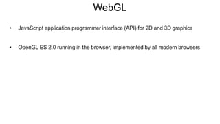
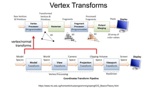
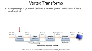
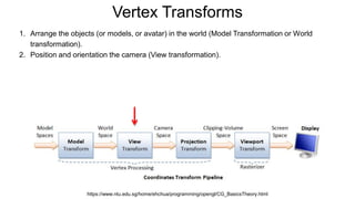
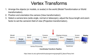
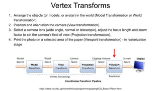
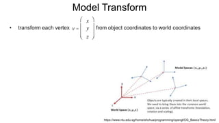
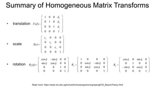
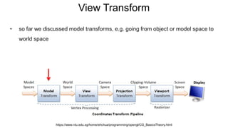
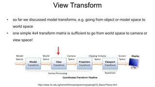
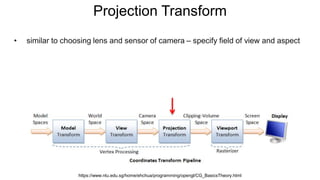
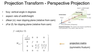
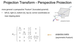
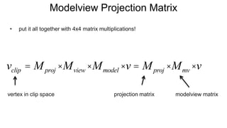
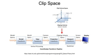
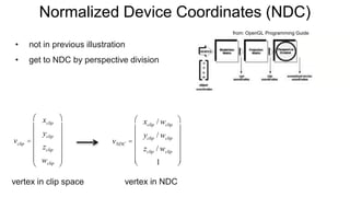
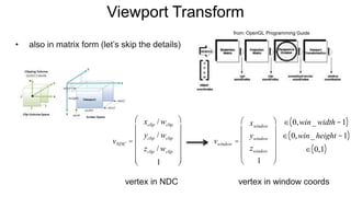
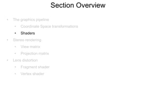
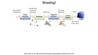
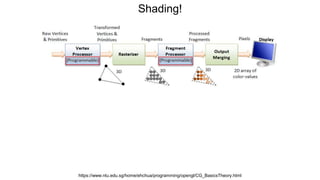
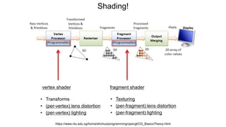
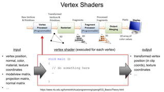
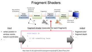
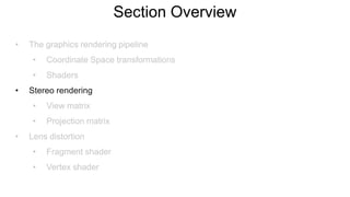
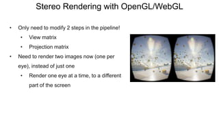
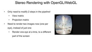
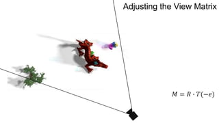
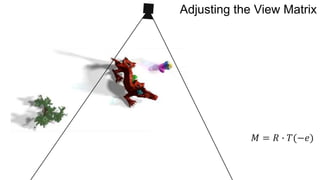
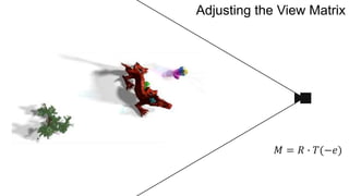
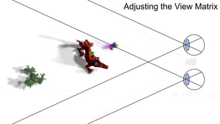
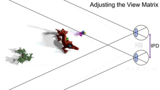
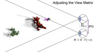
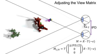
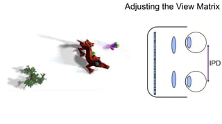
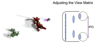
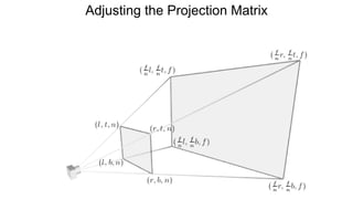
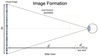
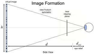
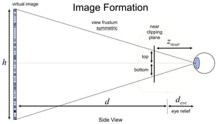
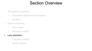
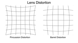
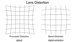
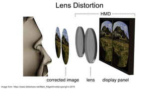
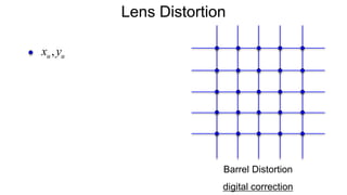
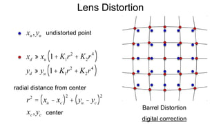
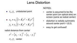
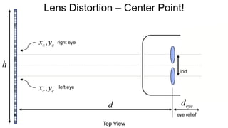
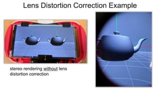
Build Your Own VR Display
The Graphics Pipeline, Stereo Rendering, and Lens Distortion
Robert Konrad
Stanford University
stanford.edu/class/ee267/
Image courtesy of Robo Recall
Albrecht Dürer, “Underweysung der Messung mit dem Zirckel und Richtscheyt”, 1525
Section Overview
• The graphics rendering pipeline
• Coordinate space transformations
• Shaders
• Stereo rendering
• View matrix
• Projection matrix
• Lens distortion
• Fragment shader
• Vertex shader
WebGL
• JavaScript application programmer interface (API) for 2D and 3D graphics
• OpenGL ES 2.0 running in the browser, implemented by all modern browsers
WebGL
• JavaScript application programmer interface (API) for 2D and 3D graphics
• OpenGL ES 2.0 running in the browser, implemented by all modern browsers
WebGL
• JavaScript application programmer interface (API) for 2D and 3D graphics
• OpenGL ES 2.0 running in the browser, implemented by all modern browsers
WebGL
• JavaScript application programmer interface (API) for 2D and 3D graphics
• OpenGL ES 2.0 running in the browser, implemented by all modern browsers
WebGL
• JavaScript application programmer interface (API) for 2D and 3D graphics
• OpenGL ES 2.0 running in the browser, implemented by all modern browsers
WebGL
• JavaScript application programmer interface (API) for 2D and 3D graphics
• OpenGL ES 2.0 running in the browser, implemented by all modern browsers
three.js
• cross-browser JavaScript library/API
• higher-level library that provides a lot of useful helper functions, tools, and
abstractions around WebGL – easy and convenient to use
• https://threejs.org/
• simple examples: https://threejs.org/examples/
• great introduction (in WebGL):
http://davidscottlyons.com/threejs/presentations/frontporch14/
Computer Graphics!
• at the most basic level: conversion from 3D scene description to 2D image
• what do you need to describe a static scene?
• 3D geometry and transformations
• lights
• material properties / textures
• Represent object surfaces as a set of primitive shapes
• Points / Lines / Triangles / Quad (rilateral) s
Tesselation
The Graphics Pipeline
https://www.ntu.edu.sg/home/ehchua/programming/opengl/CG_BasicsTheory.html
1. Vertex Processing: Process and transform individual vertices with attributes (position, color, vertex
normals, texture coordinates, etc.)
The Graphics Pipeline
https://www.ntu.edu.sg/home/ehchua/programming/opengl/CG_BasicsTheory.html
1. Vertex Processing: Process and transform individual vertices with attributes (position, color, vertex
normals, texture coordinates, etc.)
2. Rasterization: Convert each primitive (connected vertices) into a set of fragments. A fragment can
be treated as a pixel in 3D spaces, which is aligned with the pixel grid, with attributes interpolated
from the vertices.
3. Fragment Processing: Process individual fragments.
4. Output Merging: Combine the fragments of all primitives (in 3D space) into 2D color-pixel for the
display.
Coordinate Systems
• right hand coordinate system
• a few different coordinate systems:
• object coordinates
• world coordinates
• viewing coordinates
• also clip, normalized device, and
window coordinates
wikipedia
Vertex Transforms
https://www.ntu.edu.sg/home/ehchua/programming/opengl/CG_BasicsTheory.html
Vertex Transforms
https://www.ntu.edu.sg/home/ehchua/programming/opengl/CG_BasicsTheory.html
vertex/normal
transforms
Vertex Transforms
https://www.ntu.edu.sg/home/ehchua/programming/opengl/CG_BasicsTheory.html
1. Arrange the objects (or models, or avatar) in the world (Model Transformation or World
transformation).
Vertex Transforms
https://www.ntu.edu.sg/home/ehchua/programming/opengl/CG_BasicsTheory.html
1. Arrange the objects (or models, or avatar) in the world (Model Transformation or World
transformation).
2. Position and orientation the camera (View transformation).
Vertex Transforms
https://www.ntu.edu.sg/home/ehchua/programming/opengl/CG_BasicsTheory.html
1. Arrange the objects (or models, or avatar) in the world (Model Transformation or World
transformation).
2. Position and orientation the camera (View transformation).
3. Select a camera lens (wide angle, normal or telescopic), adjust the focus length and zoom
factor to set the camera's field of view (Projection transformation).
4. Print the photo on a selected area of the paper (Viewport transformation) - in rasterization
stage
Model Transform
• transform each vertex from object coordinates to world coordinates
https://www.ntu.edu.sg/home/ehchua/programming/opengl/CG_BasicsTheory.html
v =
x
y
z
æ
è
ç
ç
ç
ö
ø
÷
÷
÷
Summary of Homogeneous Matrix Transforms
• translation
• scale
• rotation Rx =
1 0 0 0
0 cosq -sinq 0
0 sinq cosq 0
0 0 0 1
æ
è
ç
ç
ç
ç
ö
ø
÷
÷
÷
÷
Ry =
cosq 0 sinq 0
0 1 0 0
-sinq 0 cosq 0
0 0 0 1
æ
è
ç
ç
ç
ç
ö
ø
÷
÷
÷
÷
Read more: https://www.ntu.edu.sg/home/ehchua/programming/opengl/CG_BasicsTheory.html
T(d) =
1 0 0 dx
0 1 0 dy
0 0 1 dz
0 0 0 1
æ
è
ç
ç
ç
ç
ç
ö
ø
÷
÷
÷
÷
÷
S(s) =
sx 0 0 0
0 sy 0 0
0 0 sz 0
0 0 0 1
æ
è
ç
ç
ç
ç
ç
ö
ø
÷
÷
÷
÷
÷
Rz (q) =
cosq -sinq 0 0
sinq cosq 0 0
0 0 1 0
0 0 0 1
æ
è
ç
ç
ç
ç
ö
ø
÷
÷
÷
÷
Summary of Homogeneous Matrix Transforms
• translation inverse translation
• scale inverse scale
• rotation inverse rotation
T(d) =
1 0 0 dx
0 1 0 dy
0 0 1 dz
0 0 0 1
æ
è
ç
ç
ç
ç
ç
ö
ø
÷
÷
÷
÷
÷
S(s) =
sx 0 0 0
0 sy 0 0
0 0 sz 0
0 0 0 1
æ
è
ç
ç
ç
ç
ç
ö
ø
÷
÷
÷
÷
÷
Rz (q) =
cosq -sinq 0 0
sinq cosq 0 0
0 0 1 0
0 0 0 1
æ
è
ç
ç
ç
ç
ö
ø
÷
÷
÷
÷
Read more: https://www.ntu.edu.sg/home/ehchua/programming/opengl/CG_BasicsTheory.html
T -1
(d) = T(-d) =
1 0 0 -dx
0 1 0 -dy
0 0 1 -dz
0 0 0 1
æ
è
ç
ç
ç
ç
ç
ö
ø
÷
÷
÷
÷
÷
S-1
(s) = S
1
s
æ
èç
ö
ø÷ =
1/ sx 0 0 0
0 1/ sy 0 0
0 0 1/ sz 0
0 0 0 1
æ
è
ç
ç
ç
ç
ç
ö
ø
÷
÷
÷
÷
÷
Rz
-1
(q) = Rz -q( ) =
cos-q -sin-q 0 0
sin-q cos-q 0 0
0 0 1 0
0 0 0 1
æ
è
ç
ç
ç
ç
ö
ø
÷
÷
÷
÷
Summary of Homogeneous Matrix Transforms
• successive transforms:
• inverse successive transforms:
v' = T ×S×Rz ×Rx ×T ×v
Read more: https://www.ntu.edu.sg/home/ehchua/programming/opengl/CG_BasicsTheory.html
v = T ×S× Rz × Rx ×T( )
-1
×v'
= T -1
× Rx
-1
× Rz
-1
×S-1
×T -1
×v'
Attention!
• rotations and translations (or transforms in general) are not commutative!
• make sure you get the correct order!
View Transform
• so far we discussed model transforms, e.g. going from object or model space to
world space
https://www.ntu.edu.sg/home/ehchua/programming/opengl/CG_BasicsTheory.html
View Transform
• so far we discussed model transforms, e.g. going from object or model space to
world space
• one simple 4x4 transform matrix is sufficient to go from world space to camera or
view space!
https://www.ntu.edu.sg/home/ehchua/programming/opengl/CG_BasicsTheory.html
View Transform
specify camera by
• eye position
• reference position
• up vector
eye =
eyex
eyey
eyez
æ
è
ç
ç
ç
ö
ø
÷
÷
÷
up =
upx
upy
upz
æ
è
ç
ç
ç
ö
ø
÷
÷
÷
center =
centerx
centery
centerz
æ
è
ç
ç
ç
ö
ø
÷
÷
÷
View Transform
specify camera by
• eye position
• reference position
• up vector up =
upx
upy
upz
æ
è
ç
ç
ç
ö
ø
÷
÷
÷
center =
centerx
centery
centerz
æ
è
ç
ç
ç
ö
ø
÷
÷
÷
compute 3 vectors:
eye =
eyex
eyey
eyez
æ
è
ç
ç
ç
ö
ø
÷
÷
÷
xc
=
up ´ zc
up ´ zc
yc
= zc
´ xc
zc
=
eye- center
eye- center
View Transform
view transform is translation into eye position,
followed by rotation
xc
=
up ´ zc
up ´ zc
yc
= zc
´ xc
compute 3 vectors:M
zc
=
eye- center
eye- center
View Transform
view transform is translation into eye position,
followed by rotation
xc
=
up ´ zc
up ´ zc
yc
= zc
´ xc
compute 3 vectors:M
zc
=
eye- center
eye- center
M = R×T(-e) =
xx
c
xy
c
xz
c
0
yx
c
yy
c
yz
c
0
zx
c
zy
c
zz
c
0
0 0 0 1
æ
è
ç
ç
ç
ç
ç
ö
ø
÷
÷
÷
÷
÷
1 0 0 -eyex
0 1 0 -eyey
0 0 1 -eyez
0 0 0 1
æ
è
ç
ç
ç
ç
ç
ö
ø
÷
÷
÷
÷
÷
View Transform
view transform is translation into eye position,
followed by rotation
M
M = R×T(-e) =
xx
c
xy
c
xz
c
- xx
c
eyex + xy
c
eyey + xz
c
eyez( )
yx
c
yy
c
yz
c
- yx
c
eyex + yy
c
eyey + yz
c
eyez( )
zx
c
zy
c
zz
c
- zx
c
eyex + zy
c
eyey + zz
c
eyez( )
0 0 0 1
æ
è
ç
ç
ç
ç
ç
ç
ö
ø
÷
÷
÷
÷
÷
÷
View Transform
• in camera/view space, the camera is at the origin, looking into negative z
• modelview matrix is combined model (rotations, translations, scales) and view
matrix!
https://www.ntu.edu.sg/home/ehchua/programming/opengl/CG_BasicsTheory.html
View Transform
• in camera/view space, the camera is at the origin, looking into negative z
vodacek.zvb.cz
x
x
z
z
up
e
Projection Transform
• similar to choosing lens and sensor of camera – specify field of view and aspect
https://www.ntu.edu.sg/home/ehchua/programming/opengl/CG_BasicsTheory.html
Projection Transform - Perspective Projection
• fovy: vertical angle in degrees
• aspect: ratio of width/height
• zNear (n): near clipping plane (relative from cam)
• zFar (f): far clipping plane (relative from cam)
M proj =
f
aspect
0 0 0
0 f 0 0
0 0
n + f
n - f
2× f ×n
n - f
0 0 -1 0
æ
è
ç
ç
ç
ç
ç
ç
ç
ö
ø
÷
÷
÷
÷
÷
÷
÷
f = cot( fovy / 2)
projection matrix
(symmetric frustum)
Projection Transform - Perspective Projection
more general: a perspective “frustum” (truncated pyramid)
• left (l), right (r), bottom (b), top (t): corner coordinates on
near clipping plane
M proj =
2n
r - l
0
r + l
r - l
0
0
2n
t - b
t + b
t - b
0
0 0 -
f + n
f - n
-2× f ×n
f - n
0 0 -1 0
æ
è
ç
ç
ç
ç
ç
ç
ç
ç
ö
ø
÷
÷
÷
÷
÷
÷
÷
÷
projection matrix
(asymmetric frustum)
perspective frustum
Modelview Projection Matrix
• put it all together with 4x4 matrix multiplications!
projection matrix modelview matrixvertex in clip space
vclip = Mproj ×Mview ×Mmodel ×v = Mproj ×Mmv ×v
Clip Space
https://www.ntu.edu.sg/home/ehchua/programming/opengl/CG_BasicsTheory.html
Normalized Device Coordinates (NDC)
• not in previous illustration
• get to NDC by perspective division
from: OpenGL Programming Guide
vclip =
xclip
yclip
zclip
wclip
æ
è
ç
ç
ç
ç
ç
ö
ø
÷
÷
÷
÷
÷
vNDC =
xclip / wclip
yclip / wclip
zclip / wclip
1
æ
è
ç
ç
ç
ç
ç
ö
ø
÷
÷
÷
÷
÷
vertex in clip space vertex in NDC
Viewport Transform
• also in matrix form (let’s skip the details)
from: OpenGL Programming Guide
vNDC =
xclip / wclip
yclip / wclip
zclip / wclip
1
æ
è
ç
ç
ç
ç
ç
ö
ø
÷
÷
÷
÷
÷
vertex in NDC
vwindow =
xwindow
ywindow
zwindow
1
æ
è
ç
ç
ç
ç
ö
ø
÷
÷
÷
÷
Î 0,win_width -1( )
Î 0,win_height -1( )
Î 0,1( )
vertex in window coords
Section Overview
• The graphics pipeline
• Coordinate Space transformations
• Shaders
• Stereo rendering
• View matrix
• Projection matrix
• Lens distortion
• Fragment shader
• Vertex shader
Shading!
https://www.ntu.edu.sg/home/ehchua/programming/opengl/CG_BasicsTheory.html
Shading!
https://www.ntu.edu.sg/home/ehchua/programming/opengl/CG_BasicsTheory.html
Vertex and Fragment Shaders
• shaders are small programs that are executed in parallel on the GPU for each
vertex (vertex shader) or each fragment (fragment shader)
• vertex shader:
• modelview projection transform of vertex & normal (see last lecture)
• if per-vertex lighting: do lighting calculations here (otherwise omit)
• fragment shader:
• assign final color to each fragment
• if per-fragment lighting: do all lighting calculations here (otherwise omit)
Shading!
https://www.ntu.edu.sg/home/ehchua/programming/opengl/CG_BasicsTheory.html
vertex shader fragment shader
• Transforms
• (per-vertex) lens distortion
• (per-vertex) lighting
• Texturing
• (per-fragment) lens distortion
• (per-fragment) lighting
Vertex Shaders
https://www.ntu.edu.sg/home/ehchua/programming/opengl/CG_BasicsTheory.html
vertex shader (executed for each vertex)input output
• vertex position,
normal, color,
material, texture
coordinates
• modelview matrix,
projection matrix,
normal matrix
• …
• transformed vertex
position (in clip
coords), texture
coordinates
• …
void main ()
{
// do something here
…
}
Fragment Shaders
https://www.ntu.edu.sg/home/ehchua/programming/opengl/CG_BasicsTheory.html
input output
• vertex position in
window coords,
texture coordinates
• …
• fragment color
• fragment depth
• …
void main ()
{
// do something here
…
}
fragment shader (executed for each fragment)
Why Do We Need Shaders?
• massively parallel computing
• single instruction multiple data (SIMD) paradigm  GPUs are
designed to be parallel processors
• vertex shaders are independently executed for each vertex on
GPU (in parallel)
• fragment shaders are independently executed for each
fragment on GPU (in parallel)
• most important: vertex transforms and lighting & shading calculations
• shading: how to compute color of each fragment (e.g. interpolate colors)
1. Flat shading
2. Gouraud shading (per-vertex shading)
3. Phong shading (per-fragment shading)
• other: render motion blur, depth of field, physical simulation, …
courtesy: Intergraph Computer Systems
Why Do We Need Shaders?
Shading Languages
• Cg (C for Graphics – NVIDIA, deprecated)
• GLSL (GL Shading Language – OpenGL)
• HLSL (High Level Shading Language - MS Direct3D)
OpenGL Shading Language (GLSL)
• high-level programming language for shaders
• syntax similar to C (i.e. has main function and many other similarities)
• usually very short programs that are executed in parallel on GPU
• good introduction / tutorial:
https://www.opengl.org/sdk/docs/tutorials/TyphoonLabs/
• versions of OpenGL, WebGL, GLSL can get confusing
• here’s what we use:
• WebGL 1.0 - based on OpenGL ES 2.0
• GLSL 1.10 - shader preprocessor: #version 110
• reason: three.js doesn’t support WebGL 2.0 yet
OpenGL Shading Language (GLSL)
Section Overview
• The graphics rendering pipeline
• Coordinate Space transformations
• Shaders
• Stereo rendering
• View matrix
• Projection matrix
• Lens distortion
• Fragment shader
• Vertex shader
Depth Perception monocular cues
• perspective
• relative object size
• absolute size
• occlusion
• accommodation
• retinal blur
• motion parallax
• texture gradients
• shading
• …
wikipedia
binocular cues
• (con)vergence
• disparity / parallax
• …
binocular disparity motion parallax accommodation/blurconvergence
current glasses-based (stereoscopic) displays
near-term: light field displays
longer-term: holographic displays
Depth Perception
Depth Perception
Cutting&Vishton,1995
Walker, Lewis E., 1865. Hon. Abraham Lincoln, President of the United States. Library of CongressCharles Wheatstone., 1841. Stereoscope.
Stereoscopic Displays
Parallax
• parallax is the relative distance of a 3D point projected into the 2 stereo images
case 1 case 2 case 3
http://paulbourke.net/stereographics/stereorender/
Parallax
• visual system only uses horizontal parallax, no vertical parallax!
• naïve toe-in method creates vertical parallax  visual discomfort
Toe-in = incorrect! Off-axis = correct!
http://paulbourke.net/stereographics/stereorender/
Parallax – well done
1862
“Tending wounded Union soldiers at
Savage's Station, Virginia, during the
Peninsular Campaign”,
Library of Congress Prints and
Photographs Division
Parallax – not well done
All Current-generation VR HMDs are
“Simple Magnifiers”
Stereo Rendering for HMDs
Image Formation
HMD
lens
Side View
micro
display
Image Formation
HMD
lens
Side View
deye
eye relief
micro
display
f
d'
h'
Image Formation
HMD
virtual image
Side View
d
h
deye
eye relief
lens
micro
display
f
d'
h'
Image Formation
HMD
virtual image
Side View
d
1
d
+
1
d'
=
1
f
Û d =
1
1
f
-
1
d'
Gaussian thin lens formula:
h
deye
eye relief
lens
micro
display
f
d'
h'
Image Formation
HMD
virtual image
Side View
d
1
d
+
1
d'
=
1
f
Û d =
1
1
f
-
1
d'
Gaussian thin lens formula:
Magnification:
M =
f
f - d'
Þ h = Mh'
h
deye
eye relief
lens
micro
display
f
d'
h'
Stereo Rendering with OpenGL/WebGL
• Only need to modify 2 steps in the pipeline!
• View matrix
• Projection matrix
• Need to render two images now (one per
eye), instead of just one
• Render one eye at a time, to a different
part of the screen
Stereo Rendering with OpenGL/WebGL
• Only need to modify 2 steps in the pipeline!
• View matrix
• Projection matrix
• Need to render two images now (one per
eye), instead of just one
• Render one eye at a time, to a different
part of the screen
Stereo Rendering with OpenGL/WebGL
• Only need to modify 2 steps in the pipeline!
• View matrix
• Projection matrix
• Need to render two images now (one per
eye), instead of just one
• Render one eye at a time, to a different
part of the screen
Stereo Rendering with OpenGL/WebGL
• Only need to modify 2 steps in the pipeline!
• View matrix
• Projection matrix
• Need to render two images now (one per
eye), instead of just one
• Render one eye at a time, to a different
part of the screen
𝑀 = 𝑅 ∙ 𝑇(−𝑒)
Adjusting the View Matrix
𝑀 = 𝑅 ∙ 𝑇(−𝑒)
Adjusting the View Matrix
𝑀 = 𝑅 ∙ 𝑇(−𝑒)
Adjusting the View Matrix
𝑀 = 𝑅 ∙ 𝑇(−𝑒)
Adjusting the View Matrix
IPD
𝑀 = 𝑅 ∙ 𝑇(−𝑒)
Adjusting the View Matrix
IPD
𝑀 = 𝑅 ∙ 𝑇(−𝑒)
Z
X
Adjusting the View Matrix
IPD
𝑀 = 𝑅 ∙ 𝑇(−𝑒)
Z
X
𝑀𝐿/𝑅 = 𝑇
±𝐼𝑃𝐷/2
0
0
𝑅 ∙ 𝑇(−𝑒)
Adjusting the View Matrix
IPD
Adjusting the View Matrix
IPD
Adjusting the View Matrix
IPD
Adjusting the View Matrix
IPD
Adjusting the View Matrix
Adjusting the Projection Matrix
Image Formation
HMD
virtual image
Side View
d
1
d
+
1
d'
=
1
f
Û d =
1
1
f
-
1
d'
Gaussian thin lens formula:
Magnification:
M =
f
f - d'
Þ h = Mh'
h
deye
eye relief
lens
micro
display
f
d'
h'
Image Formation
virtual image
Side View
d
h
eye relief
deye
view frustum
symmetric
Image Formation
virtual image
Side View
d
h
eye relief
deye
view frustum
symmetric near
clipping
plane
Image Formation
virtual image
Side View
d
h
eye relief
deye
view frustum
symmetric
znear
top
bottom
near
clipping
plane
Image Formation
virtual image
Side View
d
h
eye relief
deye
view frustum
symmetric
znear
top
bottom
similar triangles:
near
clipping
plane
top = znear
h
2 d + deye( )
bottom = -znear
h
2 d + deye( )
Image Formation
Top View
eye relief
deye
ipd
d'
w'
HMD
Image Formation – Left Eye
HMD
Top View
deye
eye relief
w'
2
ipd/2
HMD
virtual image
Top View
d
w1
deye
eye relief
w2
ipd/2
Image Formation – Left Eye
HMD
virtual image
Top View
d
w1
deye
eye relief
w2
w1 = M
ipd
2
w2 = M
w'- ipd
2
æ
èç
ö
ø÷
ipd/2
Image Formation – Left Eye
virtual image
Top View
d
eye relief
deye
view frustum
asymmetric
znear
near
clipping
plane
w1
w2
Image Formation – Left Eye
virtual image
Top View
d
eye relief
deye
view frustum
asymmetric
znear
right
left
near
clipping
plane
w1
w2
Image Formation – Left Eye
virtual image
Top View
d
eye relief
deye
view frustum
asymmetric
znear
right
left
similar triangles:
right = znear
w1
d + deye
left = -znear
w2
d + deye
near
clipping
plane
w1
w2
Image Formation – Left Eye
virtual image
Top View
d
eye relief
deye
view frustum
asymmetric
w1
w2
Image Formation – Right Eye
w1 = M
ipd
2
w2 = M
w'- ipd
2
æ
èç
ö
ø÷
virtual image
Top View
d
eye relief
deye
view frustum
asymmetric
znear
right
left
similar triangles:
right = znear
w2
d + deye
left = -znear
w1
d + deye
w1
w2
Image Formation – Right Eye
Prototype Specs
• ViewMaster VR Starter Pack (same specs as Google
Cardboard 1):
• lenses focal length: 45 mm
• lenses diameter: 25 mm
• interpupillary distance: 60 mm
• distance between lenses and screen: 42 mm
• Topfoison 6” LCD: width 132.5 mm, height 74.5 mm
(1920x1080 pixels)
Image Formation
• use these formulas to compute the perspective matrix in
WebGL
• you can use:
THREE.Matrix4().makePerspective(left,right,top,bottom,near,far)
THREE.Matrix4().lookAt(eye,center,up)
• that’s all you need to render stereo images on the HMD
Image Formation for More Complex Optics
• especially important in free-form optics, off-axis optical
configurations & AR
• use ray tracing – some nonlinear mapping from view frustum to
microdisplay pixels
• much more computationally challenging & sensitive to precise
calibration; our HMD and most magnifier-based designs will
work with what we discussed so far
Section Overview
• The graphics pipeline
• Coordinate Space transformations
• Shaders
• Stereo rendering
• View matrix
• Projection matrix
• Lens distortion
• Fragment shader
• Vertex shader
All lenses introduce image distortion, chromatic
aberrations, and other artifacts – we need to correct
for them as best as we can in software!
image from: https://www.slideshare.net/Mark_Kilgard/nvidia-opengl-in-2016
• grid seen through HMD lens
• lateral (xy) distortion of the
image
• chromatic aberrations:
distortion is wavelength
dependent!
Lens Distortion
Pincussion Distortion
Lens Distortion
Barrel Distortion
Pincussion Distortion
optical
Lens Distortion
Barrel Distortion
digital correction
Lens Distortion
image from: https://www.slideshare.net/Mark_Kilgard/nvidia-opengl-in-2016
Lens Distortion
Barrel Distortion
digital correction
xu,yu
Lens Distortion
Barrel Distortion
digital correction
xd » xu 1+ K1r2
+ K2r4
( )
yd » yu 1+ K1r2
+ K2r4
( )
xu,yu
r2
= xu - xc( )2
+ yu - yc( )2
undistorted point
xc,yc
radial distance from center
center
Lens Distortion
xd » xu 1+ K1r2
+ K2r4
( )
yd » yu 1+ K1r2
+ K2r4
( )
xu,yu
r2
= xu - xc( )2
+ yu - yc( )2
undistorted point
xc,yc
radial distance from center
center
NOTES:
• center is assumed to be the
center point (on optical axis) on
screen (same as lookat center)
• distortion is radially symmetric
around center point = (0,0)
• easy to get confused!
Lens Distortion – Center Point!
Top View
d
h
eye relief
deye
right eye
xc,yc
xc,yc
left eye
ipd
Lens Distortion Correction Example
stereo rendering without lens
distortion correction
Lens Distortion Correction Example
stereo rendering with lens
distortion correction
Where do we implement lens distortion correction?
• End goal: move pixels around according to optical
distortion parameters of the lenses
Where do we implement lens distortion correction?
• End goal: move pixels around according to optical
distortion parameters of the lenses
https://www.ntu.edu.sg/home/ehchua/programming/opengl/CG_BasicsTheory.html
Section Overview
• The graphics rendering pipeline
• Coordinate Space transformations
• Shaders
• Stereo rendering
• View matrix
• Projection matrix
• Lens distortion
• Fragment shader
• Vertex shader
Section Overview
Want to learn more?
• https://stanford.edu/class/ee267/
• “Fundamentals of Computer Graphics”,
Shirley and Marschner
• The graphics rendering pipeline
• Coordinate Space transformations
• Shaders
• Stereo rendering
• View matrix
• Projection matrix
• Lens distortion
• Fragment shader
• Vertex shader

Build Your Own VR Display Course - SIGGRAPH 2017: Part 2

  • 1.
    Build Your OwnVR Display The Graphics Pipeline, Stereo Rendering, and Lens Distortion Robert Konrad Stanford University stanford.edu/class/ee267/
  • 2.
    Image courtesy ofRobo Recall
  • 3.
    Albrecht Dürer, “Underweysungder Messung mit dem Zirckel und Richtscheyt”, 1525
  • 4.
    Section Overview • Thegraphics rendering pipeline • Coordinate space transformations • Shaders • Stereo rendering • View matrix • Projection matrix • Lens distortion • Fragment shader • Vertex shader
  • 5.
    WebGL • JavaScript applicationprogrammer interface (API) for 2D and 3D graphics • OpenGL ES 2.0 running in the browser, implemented by all modern browsers
  • 6.
    WebGL • JavaScript applicationprogrammer interface (API) for 2D and 3D graphics • OpenGL ES 2.0 running in the browser, implemented by all modern browsers
  • 7.
    WebGL • JavaScript applicationprogrammer interface (API) for 2D and 3D graphics • OpenGL ES 2.0 running in the browser, implemented by all modern browsers
  • 8.
    WebGL • JavaScript applicationprogrammer interface (API) for 2D and 3D graphics • OpenGL ES 2.0 running in the browser, implemented by all modern browsers
  • 9.
    WebGL • JavaScript applicationprogrammer interface (API) for 2D and 3D graphics • OpenGL ES 2.0 running in the browser, implemented by all modern browsers
  • 10.
    WebGL • JavaScript applicationprogrammer interface (API) for 2D and 3D graphics • OpenGL ES 2.0 running in the browser, implemented by all modern browsers
  • 11.
    three.js • cross-browser JavaScriptlibrary/API • higher-level library that provides a lot of useful helper functions, tools, and abstractions around WebGL – easy and convenient to use • https://threejs.org/ • simple examples: https://threejs.org/examples/ • great introduction (in WebGL): http://davidscottlyons.com/threejs/presentations/frontporch14/
  • 12.
    Computer Graphics! • atthe most basic level: conversion from 3D scene description to 2D image • what do you need to describe a static scene? • 3D geometry and transformations • lights • material properties / textures • Represent object surfaces as a set of primitive shapes • Points / Lines / Triangles / Quad (rilateral) s
  • 13.
  • 14.
    The Graphics Pipeline https://www.ntu.edu.sg/home/ehchua/programming/opengl/CG_BasicsTheory.html 1.Vertex Processing: Process and transform individual vertices with attributes (position, color, vertex normals, texture coordinates, etc.)
  • 15.
    The Graphics Pipeline https://www.ntu.edu.sg/home/ehchua/programming/opengl/CG_BasicsTheory.html 1.Vertex Processing: Process and transform individual vertices with attributes (position, color, vertex normals, texture coordinates, etc.) 2. Rasterization: Convert each primitive (connected vertices) into a set of fragments. A fragment can be treated as a pixel in 3D spaces, which is aligned with the pixel grid, with attributes interpolated from the vertices.
  • 16.
    The Graphics Pipeline https://www.ntu.edu.sg/home/ehchua/programming/opengl/CG_BasicsTheory.html 1.Vertex Processing: Process and transform individual vertices with attributes (position, color, vertex normals, texture coordinates, etc.) 2. Rasterization: Convert each primitive (connected vertices) into a set of fragments. A fragment can be treated as a pixel in 3D spaces, which is aligned with the pixel grid, with attributes interpolated from the vertices. 3. Fragment Processing: Process individual fragments.
  • 17.
    The Graphics Pipeline https://www.ntu.edu.sg/home/ehchua/programming/opengl/CG_BasicsTheory.html 1.Vertex Processing: Process and transform individual vertices with attributes (position, color, vertex normals, texture coordinates, etc.) 2. Rasterization: Convert each primitive (connected vertices) into a set of fragments. A fragment can be treated as a pixel in 3D spaces, which is aligned with the pixel grid, with attributes interpolated from the vertices. 3. Fragment Processing: Process individual fragments. 4. Output Merging: Combine the fragments of all primitives (in 3D space) into 2D color-pixel for the display.
  • 18.
    Coordinate Systems • righthand coordinate system • a few different coordinate systems: • object coordinates • world coordinates • viewing coordinates • also clip, normalized device, and window coordinates wikipedia
  • 19.
  • 20.
  • 21.
    Vertex Transforms https://www.ntu.edu.sg/home/ehchua/programming/opengl/CG_BasicsTheory.html 1. Arrangethe objects (or models, or avatar) in the world (Model Transformation or World transformation).
  • 22.
    Vertex Transforms https://www.ntu.edu.sg/home/ehchua/programming/opengl/CG_BasicsTheory.html 1. Arrangethe objects (or models, or avatar) in the world (Model Transformation or World transformation). 2. Position and orientation the camera (View transformation).
  • 23.
    Vertex Transforms https://www.ntu.edu.sg/home/ehchua/programming/opengl/CG_BasicsTheory.html 1. Arrangethe objects (or models, or avatar) in the world (Model Transformation or World transformation). 2. Position and orientation the camera (View transformation). 3. Select a camera lens (wide angle, normal or telescopic), adjust the focus length and zoom factor to set the camera's field of view (Projection transformation).
  • 24.
    Vertex Transforms https://www.ntu.edu.sg/home/ehchua/programming/opengl/CG_BasicsTheory.html 1. Arrangethe objects (or models, or avatar) in the world (Model Transformation or World transformation). 2. Position and orientation the camera (View transformation). 3. Select a camera lens (wide angle, normal or telescopic), adjust the focus length and zoom factor to set the camera's field of view (Projection transformation). 4. Print the photo on a selected area of the paper (Viewport transformation) - in rasterization stage
  • 25.
    Model Transform • transformeach vertex from object coordinates to world coordinates https://www.ntu.edu.sg/home/ehchua/programming/opengl/CG_BasicsTheory.html v = x y z æ è ç ç ç ö ø ÷ ÷ ÷
  • 26.
    Summary of HomogeneousMatrix Transforms • translation • scale • rotation Rx = 1 0 0 0 0 cosq -sinq 0 0 sinq cosq 0 0 0 0 1 æ è ç ç ç ç ö ø ÷ ÷ ÷ ÷ Ry = cosq 0 sinq 0 0 1 0 0 -sinq 0 cosq 0 0 0 0 1 æ è ç ç ç ç ö ø ÷ ÷ ÷ ÷ Read more: https://www.ntu.edu.sg/home/ehchua/programming/opengl/CG_BasicsTheory.html T(d) = 1 0 0 dx 0 1 0 dy 0 0 1 dz 0 0 0 1 æ è ç ç ç ç ç ö ø ÷ ÷ ÷ ÷ ÷ S(s) = sx 0 0 0 0 sy 0 0 0 0 sz 0 0 0 0 1 æ è ç ç ç ç ç ö ø ÷ ÷ ÷ ÷ ÷ Rz (q) = cosq -sinq 0 0 sinq cosq 0 0 0 0 1 0 0 0 0 1 æ è ç ç ç ç ö ø ÷ ÷ ÷ ÷
  • 27.
    Summary of HomogeneousMatrix Transforms • translation inverse translation • scale inverse scale • rotation inverse rotation T(d) = 1 0 0 dx 0 1 0 dy 0 0 1 dz 0 0 0 1 æ è ç ç ç ç ç ö ø ÷ ÷ ÷ ÷ ÷ S(s) = sx 0 0 0 0 sy 0 0 0 0 sz 0 0 0 0 1 æ è ç ç ç ç ç ö ø ÷ ÷ ÷ ÷ ÷ Rz (q) = cosq -sinq 0 0 sinq cosq 0 0 0 0 1 0 0 0 0 1 æ è ç ç ç ç ö ø ÷ ÷ ÷ ÷ Read more: https://www.ntu.edu.sg/home/ehchua/programming/opengl/CG_BasicsTheory.html T -1 (d) = T(-d) = 1 0 0 -dx 0 1 0 -dy 0 0 1 -dz 0 0 0 1 æ è ç ç ç ç ç ö ø ÷ ÷ ÷ ÷ ÷ S-1 (s) = S 1 s æ èç ö ø÷ = 1/ sx 0 0 0 0 1/ sy 0 0 0 0 1/ sz 0 0 0 0 1 æ è ç ç ç ç ç ö ø ÷ ÷ ÷ ÷ ÷ Rz -1 (q) = Rz -q( ) = cos-q -sin-q 0 0 sin-q cos-q 0 0 0 0 1 0 0 0 0 1 æ è ç ç ç ç ö ø ÷ ÷ ÷ ÷
  • 28.
    Summary of HomogeneousMatrix Transforms • successive transforms: • inverse successive transforms: v' = T ×S×Rz ×Rx ×T ×v Read more: https://www.ntu.edu.sg/home/ehchua/programming/opengl/CG_BasicsTheory.html v = T ×S× Rz × Rx ×T( ) -1 ×v' = T -1 × Rx -1 × Rz -1 ×S-1 ×T -1 ×v'
  • 29.
    Attention! • rotations andtranslations (or transforms in general) are not commutative! • make sure you get the correct order!
  • 30.
    View Transform • sofar we discussed model transforms, e.g. going from object or model space to world space https://www.ntu.edu.sg/home/ehchua/programming/opengl/CG_BasicsTheory.html
  • 31.
    View Transform • sofar we discussed model transforms, e.g. going from object or model space to world space • one simple 4x4 transform matrix is sufficient to go from world space to camera or view space! https://www.ntu.edu.sg/home/ehchua/programming/opengl/CG_BasicsTheory.html
  • 32.
    View Transform specify cameraby • eye position • reference position • up vector eye = eyex eyey eyez æ è ç ç ç ö ø ÷ ÷ ÷ up = upx upy upz æ è ç ç ç ö ø ÷ ÷ ÷ center = centerx centery centerz æ è ç ç ç ö ø ÷ ÷ ÷
  • 33.
    View Transform specify cameraby • eye position • reference position • up vector up = upx upy upz æ è ç ç ç ö ø ÷ ÷ ÷ center = centerx centery centerz æ è ç ç ç ö ø ÷ ÷ ÷ compute 3 vectors: eye = eyex eyey eyez æ è ç ç ç ö ø ÷ ÷ ÷ xc = up ´ zc up ´ zc yc = zc ´ xc zc = eye- center eye- center
  • 34.
    View Transform view transformis translation into eye position, followed by rotation xc = up ´ zc up ´ zc yc = zc ´ xc compute 3 vectors:M zc = eye- center eye- center
  • 35.
    View Transform view transformis translation into eye position, followed by rotation xc = up ´ zc up ´ zc yc = zc ´ xc compute 3 vectors:M zc = eye- center eye- center M = R×T(-e) = xx c xy c xz c 0 yx c yy c yz c 0 zx c zy c zz c 0 0 0 0 1 æ è ç ç ç ç ç ö ø ÷ ÷ ÷ ÷ ÷ 1 0 0 -eyex 0 1 0 -eyey 0 0 1 -eyez 0 0 0 1 æ è ç ç ç ç ç ö ø ÷ ÷ ÷ ÷ ÷
  • 36.
    View Transform view transformis translation into eye position, followed by rotation M M = R×T(-e) = xx c xy c xz c - xx c eyex + xy c eyey + xz c eyez( ) yx c yy c yz c - yx c eyex + yy c eyey + yz c eyez( ) zx c zy c zz c - zx c eyex + zy c eyey + zz c eyez( ) 0 0 0 1 æ è ç ç ç ç ç ç ö ø ÷ ÷ ÷ ÷ ÷ ÷
  • 37.
    View Transform • incamera/view space, the camera is at the origin, looking into negative z • modelview matrix is combined model (rotations, translations, scales) and view matrix! https://www.ntu.edu.sg/home/ehchua/programming/opengl/CG_BasicsTheory.html
  • 38.
    View Transform • incamera/view space, the camera is at the origin, looking into negative z vodacek.zvb.cz x x z z up e
  • 39.
    Projection Transform • similarto choosing lens and sensor of camera – specify field of view and aspect https://www.ntu.edu.sg/home/ehchua/programming/opengl/CG_BasicsTheory.html
  • 40.
    Projection Transform -Perspective Projection • fovy: vertical angle in degrees • aspect: ratio of width/height • zNear (n): near clipping plane (relative from cam) • zFar (f): far clipping plane (relative from cam) M proj = f aspect 0 0 0 0 f 0 0 0 0 n + f n - f 2× f ×n n - f 0 0 -1 0 æ è ç ç ç ç ç ç ç ö ø ÷ ÷ ÷ ÷ ÷ ÷ ÷ f = cot( fovy / 2) projection matrix (symmetric frustum)
  • 41.
    Projection Transform -Perspective Projection more general: a perspective “frustum” (truncated pyramid) • left (l), right (r), bottom (b), top (t): corner coordinates on near clipping plane M proj = 2n r - l 0 r + l r - l 0 0 2n t - b t + b t - b 0 0 0 - f + n f - n -2× f ×n f - n 0 0 -1 0 æ è ç ç ç ç ç ç ç ç ö ø ÷ ÷ ÷ ÷ ÷ ÷ ÷ ÷ projection matrix (asymmetric frustum) perspective frustum
  • 42.
    Modelview Projection Matrix •put it all together with 4x4 matrix multiplications! projection matrix modelview matrixvertex in clip space vclip = Mproj ×Mview ×Mmodel ×v = Mproj ×Mmv ×v
  • 43.
  • 44.
    Normalized Device Coordinates(NDC) • not in previous illustration • get to NDC by perspective division from: OpenGL Programming Guide vclip = xclip yclip zclip wclip æ è ç ç ç ç ç ö ø ÷ ÷ ÷ ÷ ÷ vNDC = xclip / wclip yclip / wclip zclip / wclip 1 æ è ç ç ç ç ç ö ø ÷ ÷ ÷ ÷ ÷ vertex in clip space vertex in NDC
  • 45.
    Viewport Transform • alsoin matrix form (let’s skip the details) from: OpenGL Programming Guide vNDC = xclip / wclip yclip / wclip zclip / wclip 1 æ è ç ç ç ç ç ö ø ÷ ÷ ÷ ÷ ÷ vertex in NDC vwindow = xwindow ywindow zwindow 1 æ è ç ç ç ç ö ø ÷ ÷ ÷ ÷ Î 0,win_width -1( ) Î 0,win_height -1( ) Î 0,1( ) vertex in window coords
  • 46.
    Section Overview • Thegraphics pipeline • Coordinate Space transformations • Shaders • Stereo rendering • View matrix • Projection matrix • Lens distortion • Fragment shader • Vertex shader
  • 47.
  • 48.
  • 49.
    Vertex and FragmentShaders • shaders are small programs that are executed in parallel on the GPU for each vertex (vertex shader) or each fragment (fragment shader) • vertex shader: • modelview projection transform of vertex & normal (see last lecture) • if per-vertex lighting: do lighting calculations here (otherwise omit) • fragment shader: • assign final color to each fragment • if per-fragment lighting: do all lighting calculations here (otherwise omit)
  • 50.
    Shading! https://www.ntu.edu.sg/home/ehchua/programming/opengl/CG_BasicsTheory.html vertex shader fragmentshader • Transforms • (per-vertex) lens distortion • (per-vertex) lighting • Texturing • (per-fragment) lens distortion • (per-fragment) lighting
  • 51.
    Vertex Shaders https://www.ntu.edu.sg/home/ehchua/programming/opengl/CG_BasicsTheory.html vertex shader(executed for each vertex)input output • vertex position, normal, color, material, texture coordinates • modelview matrix, projection matrix, normal matrix • … • transformed vertex position (in clip coords), texture coordinates • … void main () { // do something here … }
  • 52.
    Fragment Shaders https://www.ntu.edu.sg/home/ehchua/programming/opengl/CG_BasicsTheory.html input output •vertex position in window coords, texture coordinates • … • fragment color • fragment depth • … void main () { // do something here … } fragment shader (executed for each fragment)
  • 53.
    Why Do WeNeed Shaders? • massively parallel computing • single instruction multiple data (SIMD) paradigm  GPUs are designed to be parallel processors • vertex shaders are independently executed for each vertex on GPU (in parallel) • fragment shaders are independently executed for each fragment on GPU (in parallel)
  • 54.
    • most important:vertex transforms and lighting & shading calculations • shading: how to compute color of each fragment (e.g. interpolate colors) 1. Flat shading 2. Gouraud shading (per-vertex shading) 3. Phong shading (per-fragment shading) • other: render motion blur, depth of field, physical simulation, … courtesy: Intergraph Computer Systems Why Do We Need Shaders?
  • 55.
    Shading Languages • Cg(C for Graphics – NVIDIA, deprecated) • GLSL (GL Shading Language – OpenGL) • HLSL (High Level Shading Language - MS Direct3D)
  • 56.
    OpenGL Shading Language(GLSL) • high-level programming language for shaders • syntax similar to C (i.e. has main function and many other similarities) • usually very short programs that are executed in parallel on GPU • good introduction / tutorial: https://www.opengl.org/sdk/docs/tutorials/TyphoonLabs/
  • 57.
    • versions ofOpenGL, WebGL, GLSL can get confusing • here’s what we use: • WebGL 1.0 - based on OpenGL ES 2.0 • GLSL 1.10 - shader preprocessor: #version 110 • reason: three.js doesn’t support WebGL 2.0 yet OpenGL Shading Language (GLSL)
  • 58.
    Section Overview • Thegraphics rendering pipeline • Coordinate Space transformations • Shaders • Stereo rendering • View matrix • Projection matrix • Lens distortion • Fragment shader • Vertex shader
  • 59.
    Depth Perception monocularcues • perspective • relative object size • absolute size • occlusion • accommodation • retinal blur • motion parallax • texture gradients • shading • … wikipedia binocular cues • (con)vergence • disparity / parallax • …
  • 60.
    binocular disparity motionparallax accommodation/blurconvergence current glasses-based (stereoscopic) displays near-term: light field displays longer-term: holographic displays Depth Perception
  • 61.
  • 62.
    Walker, Lewis E.,1865. Hon. Abraham Lincoln, President of the United States. Library of CongressCharles Wheatstone., 1841. Stereoscope. Stereoscopic Displays
  • 63.
  • 64.
    Parallax • parallax isthe relative distance of a 3D point projected into the 2 stereo images case 1 case 2 case 3 http://paulbourke.net/stereographics/stereorender/
  • 65.
    Parallax • visual systemonly uses horizontal parallax, no vertical parallax! • naïve toe-in method creates vertical parallax  visual discomfort Toe-in = incorrect! Off-axis = correct! http://paulbourke.net/stereographics/stereorender/
  • 66.
  • 67.
    Parallax – welldone 1862 “Tending wounded Union soldiers at Savage's Station, Virginia, during the Peninsular Campaign”, Library of Congress Prints and Photographs Division
  • 68.
  • 69.
    All Current-generation VRHMDs are “Simple Magnifiers” Stereo Rendering for HMDs
  • 70.
  • 71.
    Image Formation HMD lens Side View deye eyerelief micro display f d' h'
  • 72.
    Image Formation HMD virtual image SideView d h deye eye relief lens micro display f d' h'
  • 73.
    Image Formation HMD virtual image SideView d 1 d + 1 d' = 1 f Û d = 1 1 f - 1 d' Gaussian thin lens formula: h deye eye relief lens micro display f d' h'
  • 74.
    Image Formation HMD virtual image SideView d 1 d + 1 d' = 1 f Û d = 1 1 f - 1 d' Gaussian thin lens formula: Magnification: M = f f - d' Þ h = Mh' h deye eye relief lens micro display f d' h'
  • 75.
    Stereo Rendering withOpenGL/WebGL • Only need to modify 2 steps in the pipeline! • View matrix • Projection matrix • Need to render two images now (one per eye), instead of just one • Render one eye at a time, to a different part of the screen
  • 76.
    Stereo Rendering withOpenGL/WebGL • Only need to modify 2 steps in the pipeline! • View matrix • Projection matrix • Need to render two images now (one per eye), instead of just one • Render one eye at a time, to a different part of the screen
  • 77.
    Stereo Rendering withOpenGL/WebGL • Only need to modify 2 steps in the pipeline! • View matrix • Projection matrix • Need to render two images now (one per eye), instead of just one • Render one eye at a time, to a different part of the screen
  • 78.
    Stereo Rendering withOpenGL/WebGL • Only need to modify 2 steps in the pipeline! • View matrix • Projection matrix • Need to render two images now (one per eye), instead of just one • Render one eye at a time, to a different part of the screen
  • 79.
    𝑀 = 𝑅∙ 𝑇(−𝑒) Adjusting the View Matrix
  • 80.
    𝑀 = 𝑅∙ 𝑇(−𝑒) Adjusting the View Matrix
  • 81.
    𝑀 = 𝑅∙ 𝑇(−𝑒) Adjusting the View Matrix
  • 82.
    𝑀 = 𝑅∙ 𝑇(−𝑒) Adjusting the View Matrix
  • 83.
    IPD 𝑀 = 𝑅∙ 𝑇(−𝑒) Adjusting the View Matrix
  • 84.
    IPD 𝑀 = 𝑅∙ 𝑇(−𝑒) Z X Adjusting the View Matrix
  • 85.
    IPD 𝑀 = 𝑅∙ 𝑇(−𝑒) Z X 𝑀𝐿/𝑅 = 𝑇 ±𝐼𝑃𝐷/2 0 0 𝑅 ∙ 𝑇(−𝑒) Adjusting the View Matrix
  • 86.
  • 87.
  • 88.
  • 89.
  • 90.
  • 91.
    Image Formation HMD virtual image SideView d 1 d + 1 d' = 1 f Û d = 1 1 f - 1 d' Gaussian thin lens formula: Magnification: M = f f - d' Þ h = Mh' h deye eye relief lens micro display f d' h'
  • 92.
    Image Formation virtual image SideView d h eye relief deye view frustum symmetric
  • 93.
    Image Formation virtual image SideView d h eye relief deye view frustum symmetric near clipping plane
  • 94.
    Image Formation virtual image SideView d h eye relief deye view frustum symmetric znear top bottom near clipping plane
  • 95.
    Image Formation virtual image SideView d h eye relief deye view frustum symmetric znear top bottom similar triangles: near clipping plane top = znear h 2 d + deye( ) bottom = -znear h 2 d + deye( )
  • 96.
    Image Formation Top View eyerelief deye ipd d' w' HMD
  • 97.
    Image Formation –Left Eye HMD Top View deye eye relief w' 2 ipd/2
  • 98.
    HMD virtual image Top View d w1 deye eyerelief w2 ipd/2 Image Formation – Left Eye
  • 99.
    HMD virtual image Top View d w1 deye eyerelief w2 w1 = M ipd 2 w2 = M w'- ipd 2 æ èç ö ø÷ ipd/2 Image Formation – Left Eye
  • 100.
    virtual image Top View d eyerelief deye view frustum asymmetric znear near clipping plane w1 w2 Image Formation – Left Eye
  • 101.
    virtual image Top View d eyerelief deye view frustum asymmetric znear right left near clipping plane w1 w2 Image Formation – Left Eye
  • 102.
    virtual image Top View d eyerelief deye view frustum asymmetric znear right left similar triangles: right = znear w1 d + deye left = -znear w2 d + deye near clipping plane w1 w2 Image Formation – Left Eye
  • 103.
    virtual image Top View d eyerelief deye view frustum asymmetric w1 w2 Image Formation – Right Eye w1 = M ipd 2 w2 = M w'- ipd 2 æ èç ö ø÷
  • 104.
    virtual image Top View d eyerelief deye view frustum asymmetric znear right left similar triangles: right = znear w2 d + deye left = -znear w1 d + deye w1 w2 Image Formation – Right Eye
  • 105.
    Prototype Specs • ViewMasterVR Starter Pack (same specs as Google Cardboard 1): • lenses focal length: 45 mm • lenses diameter: 25 mm • interpupillary distance: 60 mm • distance between lenses and screen: 42 mm • Topfoison 6” LCD: width 132.5 mm, height 74.5 mm (1920x1080 pixels)
  • 106.
    Image Formation • usethese formulas to compute the perspective matrix in WebGL • you can use: THREE.Matrix4().makePerspective(left,right,top,bottom,near,far) THREE.Matrix4().lookAt(eye,center,up) • that’s all you need to render stereo images on the HMD
  • 107.
    Image Formation forMore Complex Optics • especially important in free-form optics, off-axis optical configurations & AR • use ray tracing – some nonlinear mapping from view frustum to microdisplay pixels • much more computationally challenging & sensitive to precise calibration; our HMD and most magnifier-based designs will work with what we discussed so far
  • 108.
    Section Overview • Thegraphics pipeline • Coordinate Space transformations • Shaders • Stereo rendering • View matrix • Projection matrix • Lens distortion • Fragment shader • Vertex shader
  • 109.
    All lenses introduceimage distortion, chromatic aberrations, and other artifacts – we need to correct for them as best as we can in software!
  • 110.
    image from: https://www.slideshare.net/Mark_Kilgard/nvidia-opengl-in-2016 •grid seen through HMD lens • lateral (xy) distortion of the image • chromatic aberrations: distortion is wavelength dependent! Lens Distortion
  • 111.
  • 112.
  • 113.
    Lens Distortion image from:https://www.slideshare.net/Mark_Kilgard/nvidia-opengl-in-2016
  • 114.
  • 115.
    Lens Distortion Barrel Distortion digitalcorrection xd » xu 1+ K1r2 + K2r4 ( ) yd » yu 1+ K1r2 + K2r4 ( ) xu,yu r2 = xu - xc( )2 + yu - yc( )2 undistorted point xc,yc radial distance from center center
  • 116.
    Lens Distortion xd »xu 1+ K1r2 + K2r4 ( ) yd » yu 1+ K1r2 + K2r4 ( ) xu,yu r2 = xu - xc( )2 + yu - yc( )2 undistorted point xc,yc radial distance from center center NOTES: • center is assumed to be the center point (on optical axis) on screen (same as lookat center) • distortion is radially symmetric around center point = (0,0) • easy to get confused!
  • 117.
    Lens Distortion –Center Point! Top View d h eye relief deye right eye xc,yc xc,yc left eye ipd
  • 118.
    Lens Distortion CorrectionExample stereo rendering without lens distortion correction
  • 119.
    Lens Distortion CorrectionExample stereo rendering with lens distortion correction
  • 120.
    Where do weimplement lens distortion correction? • End goal: move pixels around according to optical distortion parameters of the lenses
  • 121.
    Where do weimplement lens distortion correction? • End goal: move pixels around according to optical distortion parameters of the lenses https://www.ntu.edu.sg/home/ehchua/programming/opengl/CG_BasicsTheory.html
  • 122.
    Section Overview • Thegraphics rendering pipeline • Coordinate Space transformations • Shaders • Stereo rendering • View matrix • Projection matrix • Lens distortion • Fragment shader • Vertex shader
  • 123.
    Section Overview Want tolearn more? • https://stanford.edu/class/ee267/ • “Fundamentals of Computer Graphics”, Shirley and Marschner • The graphics rendering pipeline • Coordinate Space transformations • Shaders • Stereo rendering • View matrix • Projection matrix • Lens distortion • Fragment shader • Vertex shader