Downloaded 177 times


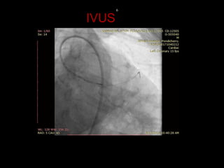
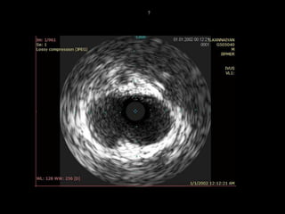


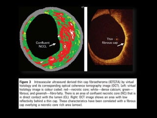
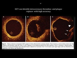


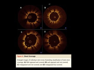


The document discusses coronary imaging techniques, primarily focusing on intravascular ultrasound (IVUS) and optical coherence tomography (OCT), detailing their applications, limitations, and safety profiles in evaluating coronary artery disease and guiding interventions. It highlights the advantages of IVUS in assessing plaque characteristics and the higher resolution of OCT for identifying features like fibrous caps and thrombus formation. The conclusion underlines the utility of these imaging modalities in improving stent implantation outcomes, with IVUS currently being the more established choice for clinical application.


