Download to read offline


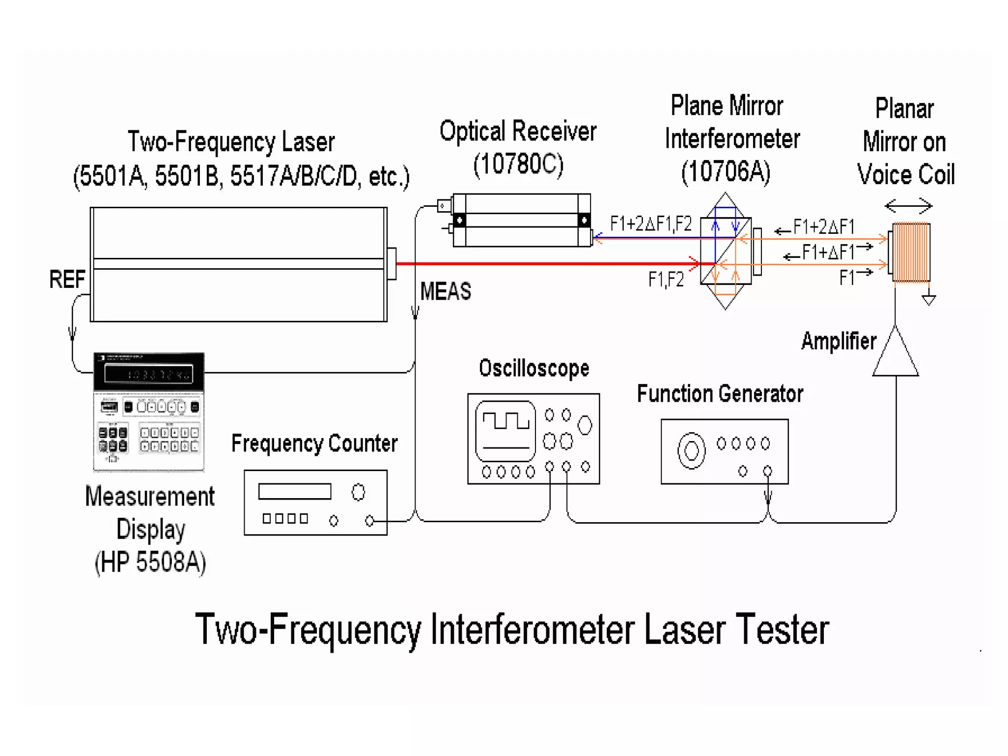


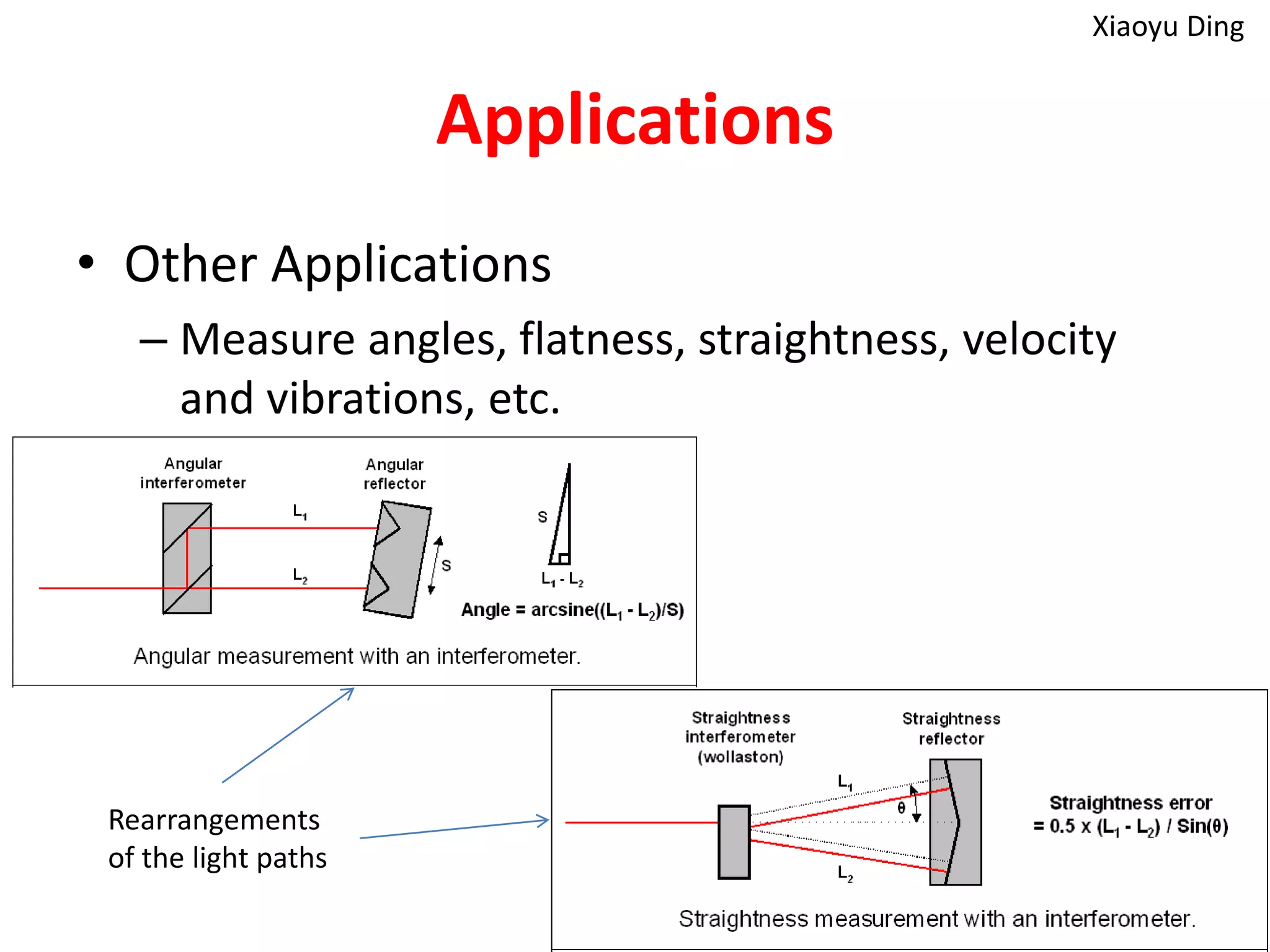


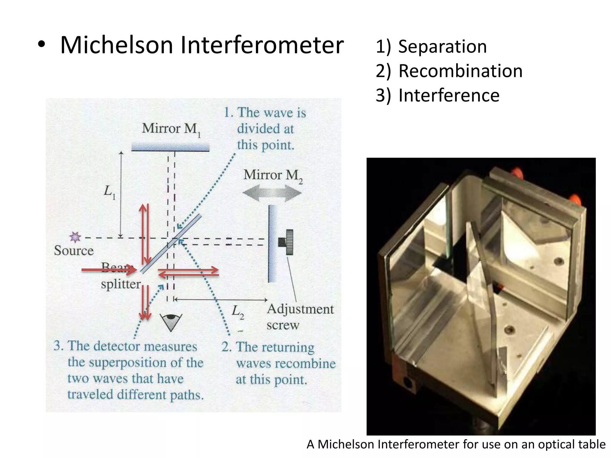
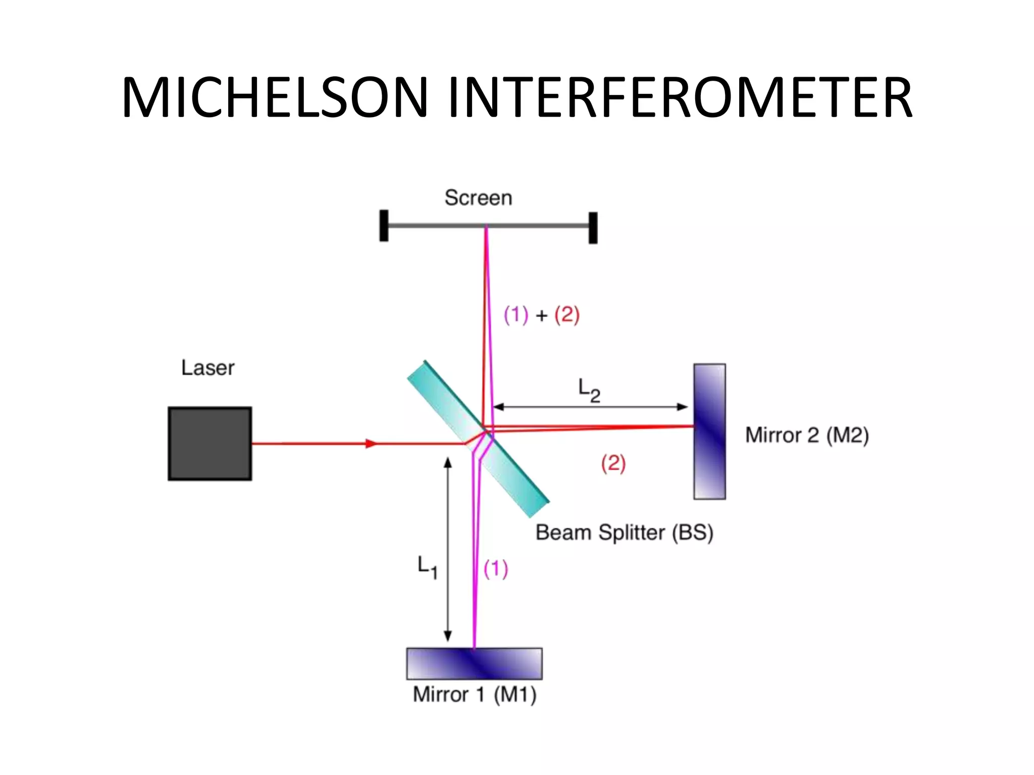
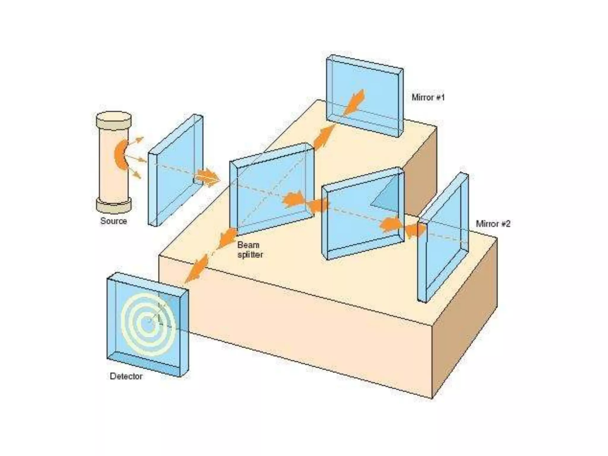


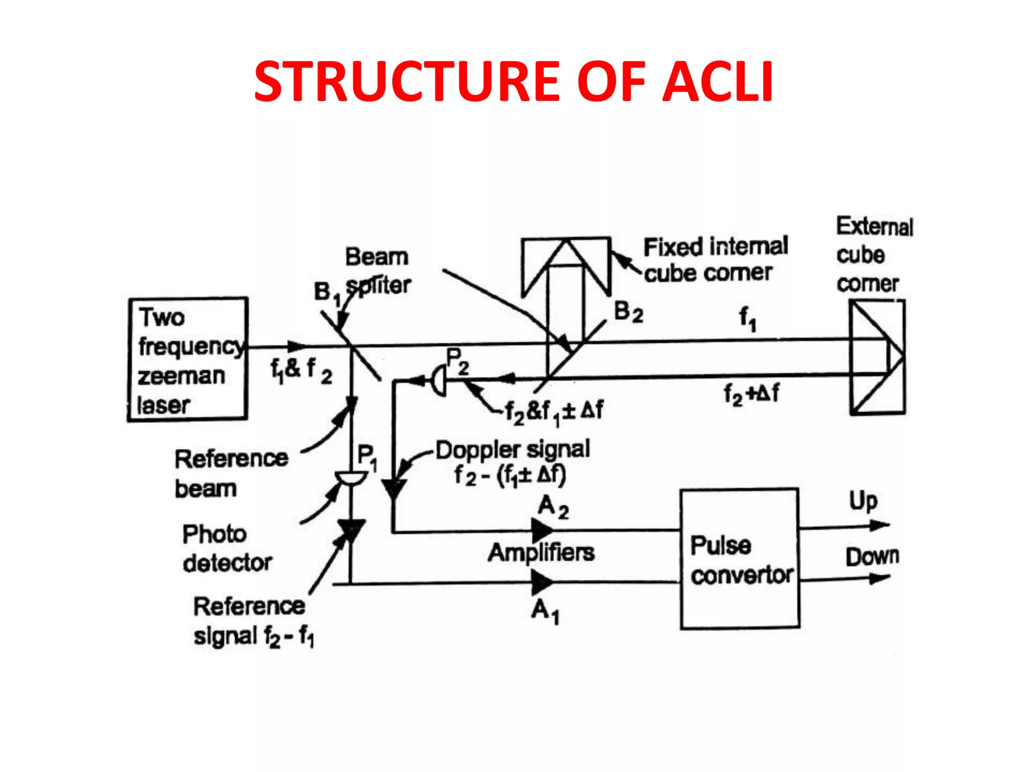

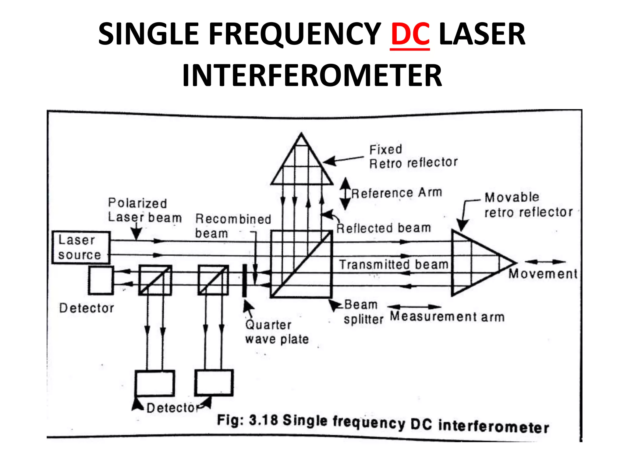


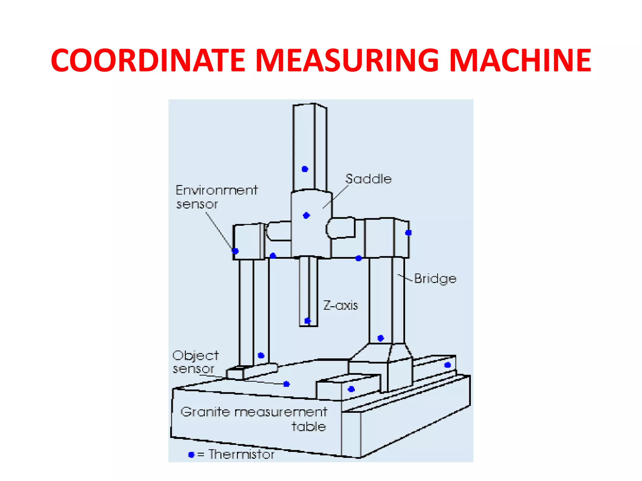

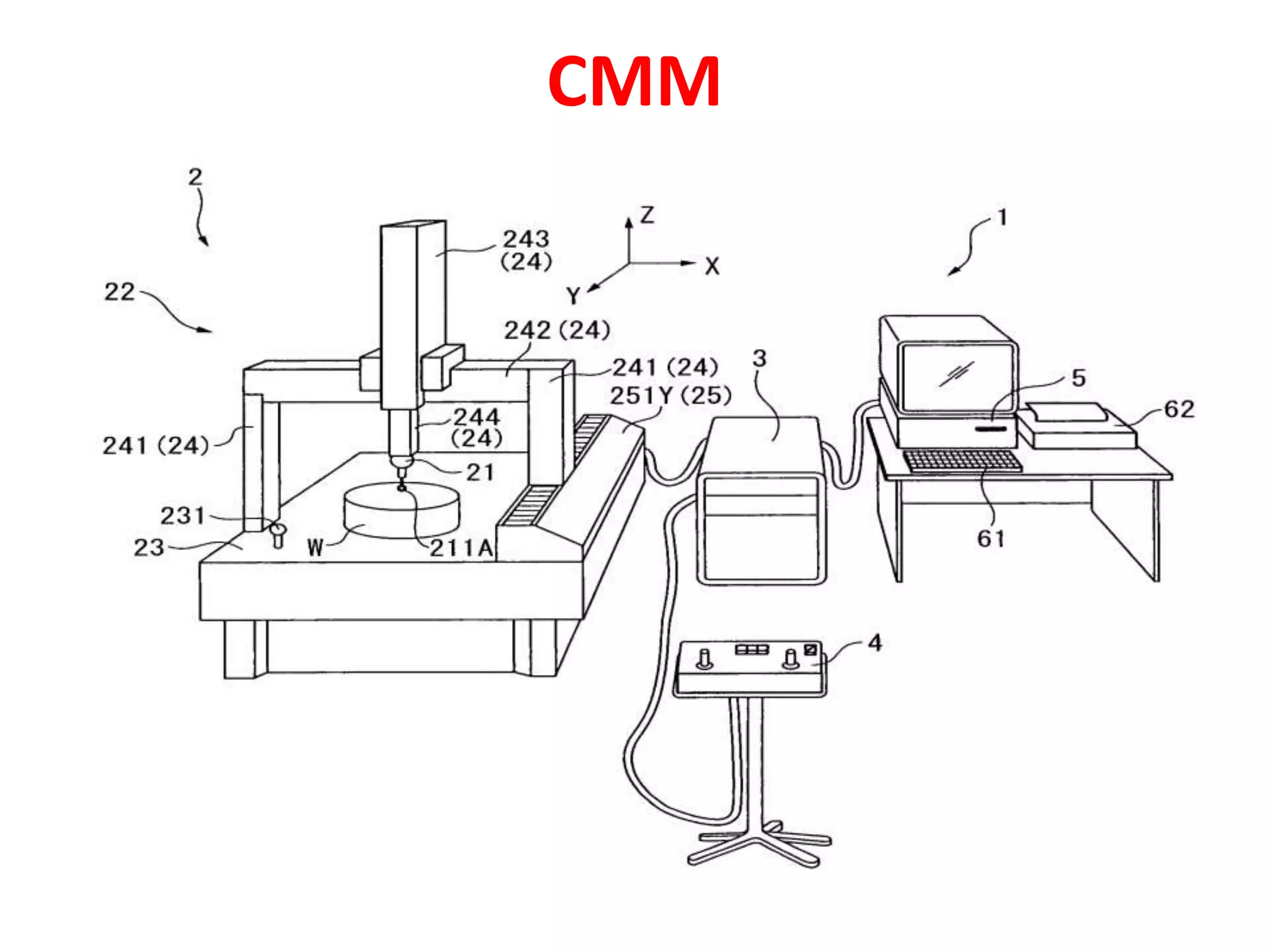


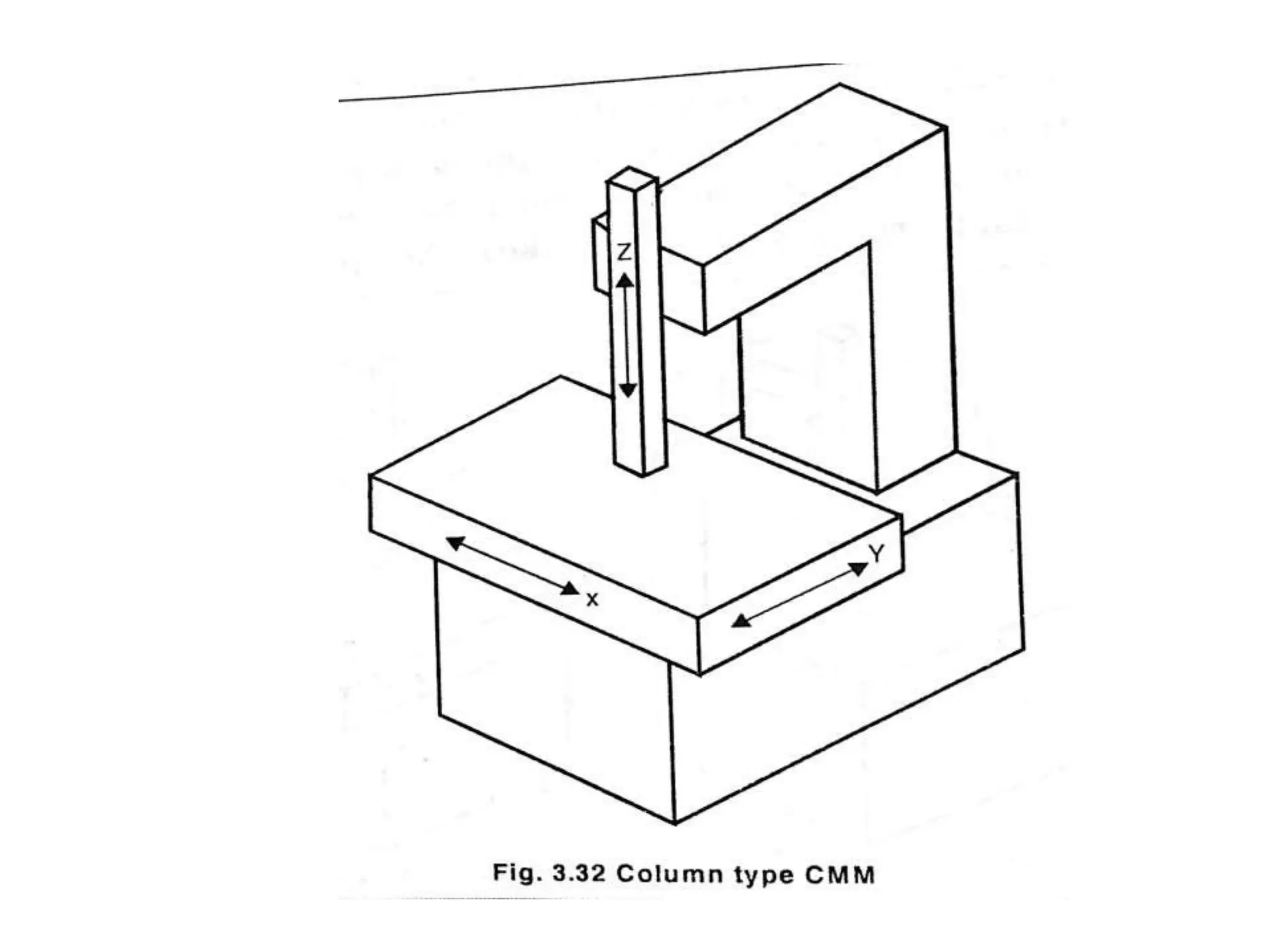
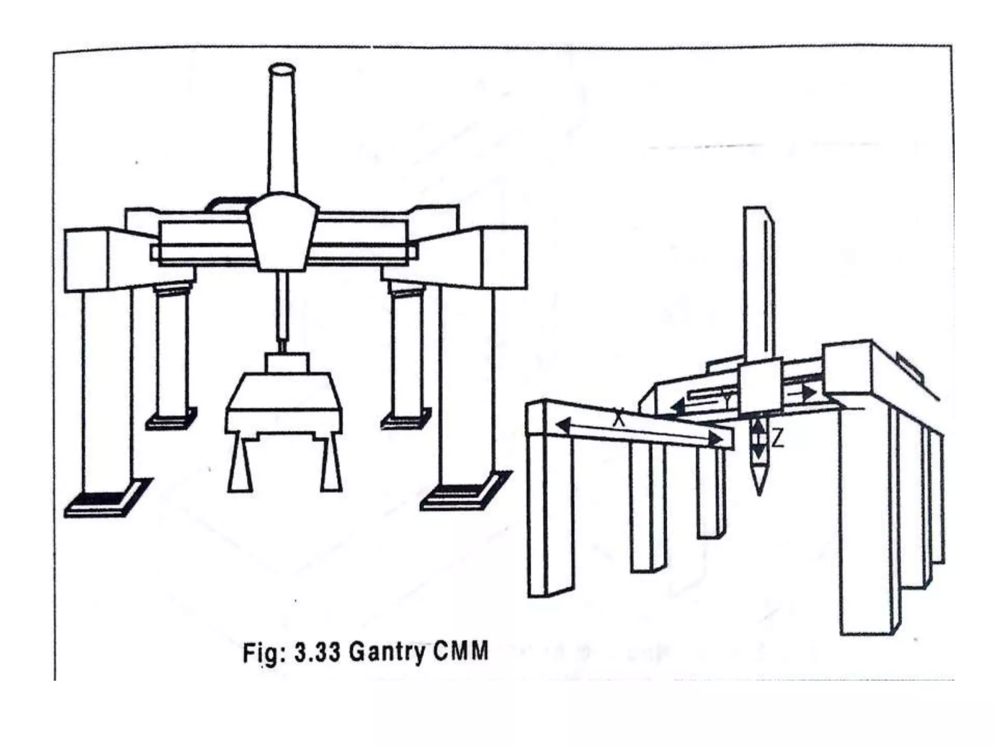


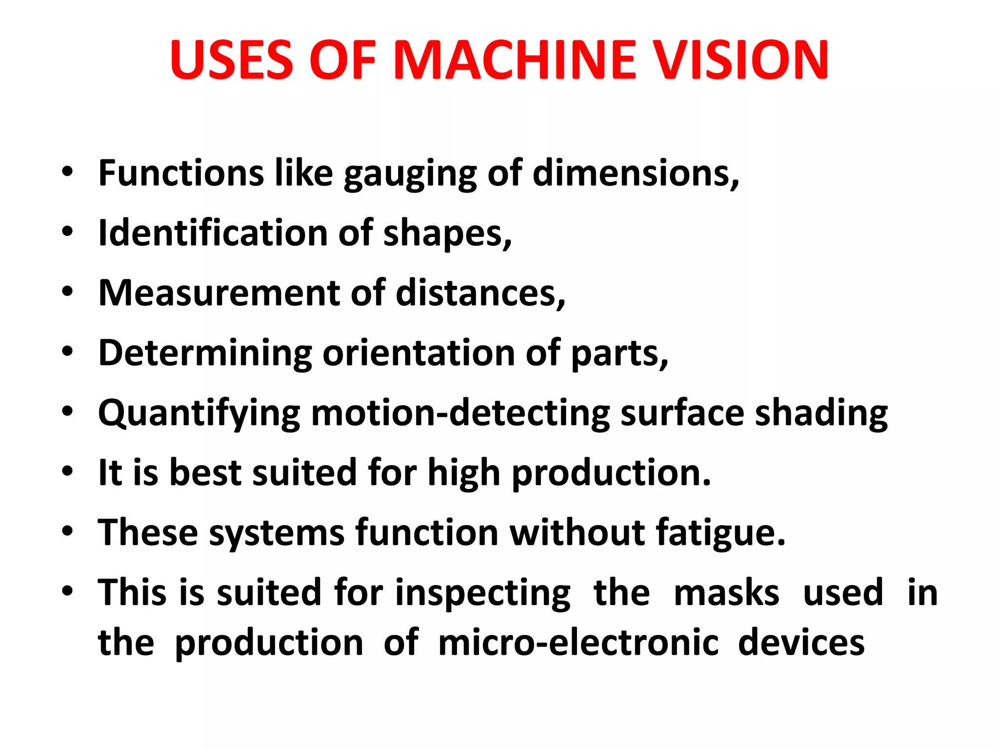


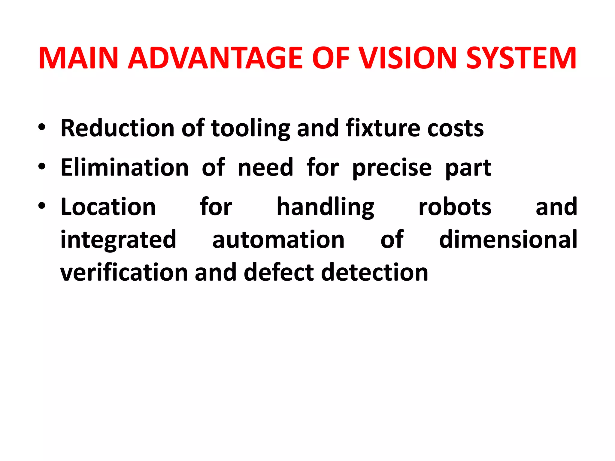
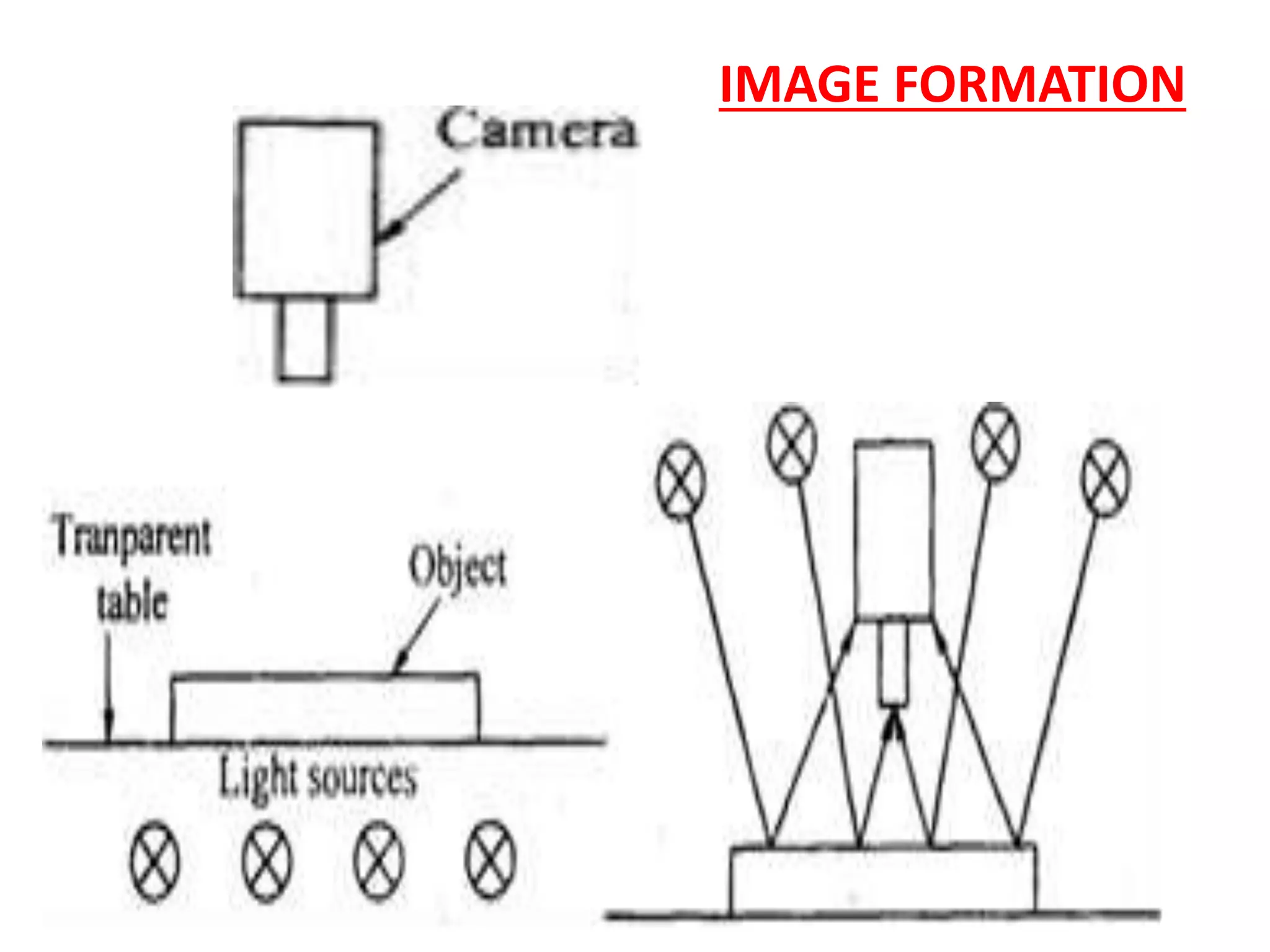


This document discusses advances in metrology, including laser interferometers, coordinate measuring machines (CMMs), and machine vision systems. Laser interferometers use laser light to perform highly precise linear and angular measurements. They can measure straightness, alignment, and small displacements. CMMs use probes to determine the coordinates of points on an object's surface, allowing precise dimensional inspection. Machine vision systems use cameras and image processing to automate visual inspection and quality control tasks.


