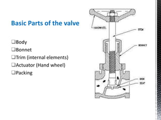
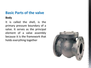
By,
Vanthian Balasubramanian
SRM UNIVERSITY
What is valve?
A valve is a device that regulates, directs or controls the flow
of a fluid by opening, closing, or partially obstructing various
passageways.
Valve Functions
 Stopping and starting fluid flow.
 Varying (throttling) the amount of fluid flow.
 Controlling the direction of fluid flow.
 Regulating downstream system or process pressure.
 Relieving component or piping over pressure.
Classification of Valves
The following are some of the commonly used valve
classifications, based on mechanical motion:
 Linear Motion Valves. The valves in which the closure
member, as in gate, globe, diaphragm, pinch moves in a
straight line to allow, stop, or throttle the flow.
 Rotary Motion Valves. When the valve-closure member
travels along an angular or circular path, as in butterfly, ball,
plug valves.
 Quarter Turn Valves. Some rotary motion valves require
approximately a quarter turn, 0 through 90°, motion of the
stem to go to fully open from a fully closed position or vice
versa.
Methods of controlling flow through a valve:
Move a disc, or plug into or against an orifice globe or needle
type.
Slide a flat, cylindrical, or spherical surface across the orifice.
Rotate a disc or ellipse about a shaft extending across the
diameter of an orifice.
Move a flexible material into the flow passage.
Basic Parts of the valve
Body
Bonnet
Trim (internal elements)
Actuator (Hand wheel)
Packing
Basic Parts of the valve
Body
It is called the shell, is the
primary pressure boundary of a
valve. It serves as the principal
element of a valve assembly
because it is the framework that
holds everything together
Bonnet
 The cover for the opening in the valve body.
 Bonnets Features
• bonnet is the second principal pressure boundary of a
valve.
• It is cast or forged of the same material as the body
and is connected to the body by a threaded, bolted, or
welded joint.
• the attachment of the bonnet to the body is
considered a pressure boundary. This means that the
weld joint or bolts that connect the bonnet to the body
are pressure-retaining parts.
• Valve bonnets, although a necessity for most valves,
represent a cause for concern,
• Bonnets can complicate the manufacture.
• Increase valve size.
• Represent a significant cost portion of valve cost.
• Bonnets are a source for potential leakage.
Valve Trim
The internal elements of a valve are
collectively referred to as a valve's
trim. The trim typically includes a
disk, seat, stem, and sleeves
needed to guide the fluid. A valve's
performance is determined by the
disk and seat interface and the
relation of the disk position to the
seat. Because of the trim, basic
motions and flow control are
possible.
Internal parts of the valve
 Disk
Disk is the third primary principal pressure boundary. It
provides the capability for allowing and stopping fluid flow. The
disk is a pressure-retaining part. Disks are typically forged and,
in some designs, hard-surfaced to provide good wear
characteristics. Most valves are named, in part, according to
the design of their disks.
 Seat or seal rings
provide the seating surface for the disk. To improve the wear-
resistance of the seal rings, the surface is often hard-faced by
welding and then machining the contact surface of the seal
ring.
Stem
Connects the actuator (hand wheel) and
disk, is responsible for positioning the disk.
Stem designs fall into four basic categories:
 Rising stem with outside screw
 Rising stem with inside screw
 Non rising stem with inside screw
 Sliding stem.
Actuator (hand
wheel)
Operates the stem and
disk assembly. An actuator
may be operated manually
or automatically.
Packing
It is used to prevent
leakage from the space
between the stem and the
bonnet.
Diaphragm Valves
A diaphragm valve is a linear motion valve that is used to start, regulate, and
stop fluid flow. The name is derived from its flexible disk, which mates with a
seat located in the open area at the top of the valve body to form a seal.
Advantages
- valve components can be isolated from the process fluid.
- Valve construction prevents leakage of the fluid without the use of a gland
seal (packing)
Disadvantages
- The diaphragm becomes worn more easily and regular maintenance is
necessary.
- These types of valves are generally not suited for very high temperature fluids
and are mainly used on liquid system
 Plug Valves
Plug valves, also called cocks, generally are used for the same full-flow service as
gate valves, where quick shutoff is required. They are used for steam, water, oil,
gas, and chemical liquid service. Plug valves are not generally designed for the
regulation of flow. Nevertheless, in some applications, specially designed plugs are
used for this purpose, particularly for gas-flow throttling. Plug valves generally can
be readily repaired or cleaned without necessitating removal of the body from
the piping system.
Advantages:
 Simple design with few parts.
 Quick to open or close.
 Can be serviced in place.
 Offers minimal resistance to flow.
 Provides reliable leak tight service. Seal can be maintained by injection of sealant or by
replacement of sleeve, in addition to utilizing the wedging action of a tapered plug.
 Multiple port design helps reduce number of valves needed and permits change in
flow direction
Disadvantages:
 Requires greater force to actuate, due to high friction.
 NPS 4 (DN 100) and larger valves require use of actuators.
 Reduced port, due to tapered plug.
 Typically, plug valves may cost more than ball valves.
Angle Valve
 These valves can be likened to mounting a globe
valve in an elbow. The exiting flow is 90 degrees to
the inlet flow.
 The obvious advantage is the elimination of an elbow,
should one be required, however the flow does make
fewer turns as it passes through the body.
 The Angle valve has little restriction on the out flow,
so if flashing or cavitation occurs then it tends to do
so further downstream from the valve. This saves not
only on the maintenance life of the valve, but also
minimises any degradation in valve performance.
 Angle valves are limited in use and are generally used
for erosive applications requiring replaceable inserts
on the out-flow piping.
Saunder Valve
 Our Saunders Type diaphragm valves have been developed to handle a wide range
of fluids and gases. Choose from a broad range of materials, methods of operation,
and body end connections to satisfy the needs of your most corrosive and abrasive
applications.
 Pocket less design for contamination free performance and smooth flow
characteristics. Linear operation ensures valve does not induce damaging pressure
surges or static charges
 The Saunders valve can be installed in any position without affecting its operation
 Extended life, reliability, safety and ease of use, combined with an essentially
simple design, results in low maintenance and cost-effective operation.
 On pressure and vacuum, Saunders diaphragm valves operate and close 100%
leaktight even after thousands of operations, reducing processing and handling
costs, by eliminating emissions normally associated with conventional valve
designs.
 All working parts of the valves are isolated from the line media and positive closure
is obtained even on frequent cycling or with entrained particulates in the line unlike
other valve types.
 Throttling and control characteristics are enhanced by a streamlined flow path that
is cavity free and provides excellent flow control capabilities.
Thank You!!!

Control valves

  • 1.
  • 2.
    What is valve? Avalve is a device that regulates, directs or controls the flow of a fluid by opening, closing, or partially obstructing various passageways. Valve Functions  Stopping and starting fluid flow.  Varying (throttling) the amount of fluid flow.  Controlling the direction of fluid flow.  Regulating downstream system or process pressure.  Relieving component or piping over pressure.
  • 3.
    Classification of Valves Thefollowing are some of the commonly used valve classifications, based on mechanical motion:  Linear Motion Valves. The valves in which the closure member, as in gate, globe, diaphragm, pinch moves in a straight line to allow, stop, or throttle the flow.  Rotary Motion Valves. When the valve-closure member travels along an angular or circular path, as in butterfly, ball, plug valves.  Quarter Turn Valves. Some rotary motion valves require approximately a quarter turn, 0 through 90°, motion of the stem to go to fully open from a fully closed position or vice versa.
  • 4.
    Methods of controllingflow through a valve: Move a disc, or plug into or against an orifice globe or needle type. Slide a flat, cylindrical, or spherical surface across the orifice. Rotate a disc or ellipse about a shaft extending across the diameter of an orifice. Move a flexible material into the flow passage.
  • 5.
    Basic Parts ofthe valve Body Bonnet Trim (internal elements) Actuator (Hand wheel) Packing
  • 6.
    Basic Parts ofthe valve Body It is called the shell, is the primary pressure boundary of a valve. It serves as the principal element of a valve assembly because it is the framework that holds everything together
  • 7.
    Bonnet  The coverfor the opening in the valve body.  Bonnets Features • bonnet is the second principal pressure boundary of a valve. • It is cast or forged of the same material as the body and is connected to the body by a threaded, bolted, or welded joint. • the attachment of the bonnet to the body is considered a pressure boundary. This means that the weld joint or bolts that connect the bonnet to the body are pressure-retaining parts. • Valve bonnets, although a necessity for most valves, represent a cause for concern, • Bonnets can complicate the manufacture. • Increase valve size. • Represent a significant cost portion of valve cost. • Bonnets are a source for potential leakage.
  • 8.
    Valve Trim The internalelements of a valve are collectively referred to as a valve's trim. The trim typically includes a disk, seat, stem, and sleeves needed to guide the fluid. A valve's performance is determined by the disk and seat interface and the relation of the disk position to the seat. Because of the trim, basic motions and flow control are possible.
  • 9.
    Internal parts ofthe valve  Disk Disk is the third primary principal pressure boundary. It provides the capability for allowing and stopping fluid flow. The disk is a pressure-retaining part. Disks are typically forged and, in some designs, hard-surfaced to provide good wear characteristics. Most valves are named, in part, according to the design of their disks.  Seat or seal rings provide the seating surface for the disk. To improve the wear- resistance of the seal rings, the surface is often hard-faced by welding and then machining the contact surface of the seal ring.
  • 10.
    Stem Connects the actuator(hand wheel) and disk, is responsible for positioning the disk. Stem designs fall into four basic categories:  Rising stem with outside screw  Rising stem with inside screw  Non rising stem with inside screw  Sliding stem.
  • 11.
    Actuator (hand wheel) Operates thestem and disk assembly. An actuator may be operated manually or automatically. Packing It is used to prevent leakage from the space between the stem and the bonnet.
  • 12.
    Diaphragm Valves A diaphragmvalve is a linear motion valve that is used to start, regulate, and stop fluid flow. The name is derived from its flexible disk, which mates with a seat located in the open area at the top of the valve body to form a seal. Advantages - valve components can be isolated from the process fluid. - Valve construction prevents leakage of the fluid without the use of a gland seal (packing) Disadvantages - The diaphragm becomes worn more easily and regular maintenance is necessary. - These types of valves are generally not suited for very high temperature fluids and are mainly used on liquid system
  • 13.
     Plug Valves Plugvalves, also called cocks, generally are used for the same full-flow service as gate valves, where quick shutoff is required. They are used for steam, water, oil, gas, and chemical liquid service. Plug valves are not generally designed for the regulation of flow. Nevertheless, in some applications, specially designed plugs are used for this purpose, particularly for gas-flow throttling. Plug valves generally can be readily repaired or cleaned without necessitating removal of the body from the piping system. Advantages:  Simple design with few parts.  Quick to open or close.  Can be serviced in place.  Offers minimal resistance to flow.  Provides reliable leak tight service. Seal can be maintained by injection of sealant or by replacement of sleeve, in addition to utilizing the wedging action of a tapered plug.  Multiple port design helps reduce number of valves needed and permits change in flow direction Disadvantages:  Requires greater force to actuate, due to high friction.  NPS 4 (DN 100) and larger valves require use of actuators.  Reduced port, due to tapered plug.  Typically, plug valves may cost more than ball valves.
  • 14.
    Angle Valve  Thesevalves can be likened to mounting a globe valve in an elbow. The exiting flow is 90 degrees to the inlet flow.  The obvious advantage is the elimination of an elbow, should one be required, however the flow does make fewer turns as it passes through the body.  The Angle valve has little restriction on the out flow, so if flashing or cavitation occurs then it tends to do so further downstream from the valve. This saves not only on the maintenance life of the valve, but also minimises any degradation in valve performance.  Angle valves are limited in use and are generally used for erosive applications requiring replaceable inserts on the out-flow piping.
  • 15.
    Saunder Valve  OurSaunders Type diaphragm valves have been developed to handle a wide range of fluids and gases. Choose from a broad range of materials, methods of operation, and body end connections to satisfy the needs of your most corrosive and abrasive applications.  Pocket less design for contamination free performance and smooth flow characteristics. Linear operation ensures valve does not induce damaging pressure surges or static charges  The Saunders valve can be installed in any position without affecting its operation  Extended life, reliability, safety and ease of use, combined with an essentially simple design, results in low maintenance and cost-effective operation.  On pressure and vacuum, Saunders diaphragm valves operate and close 100% leaktight even after thousands of operations, reducing processing and handling costs, by eliminating emissions normally associated with conventional valve designs.  All working parts of the valves are isolated from the line media and positive closure is obtained even on frequent cycling or with entrained particulates in the line unlike other valve types.  Throttling and control characteristics are enhanced by a streamlined flow path that is cavity free and provides excellent flow control capabilities.
  • 16.