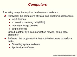
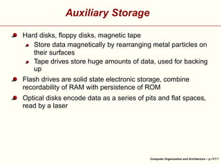
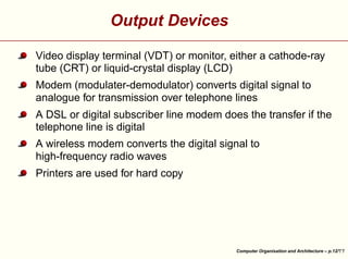
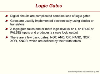
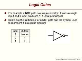
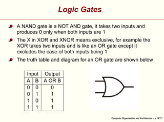
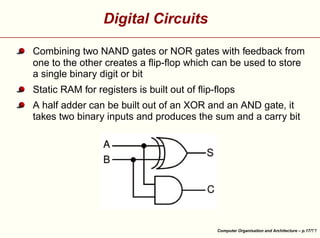
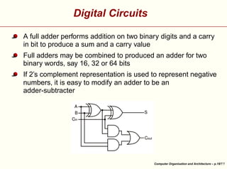
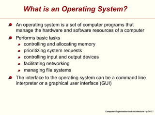
Computer Organisation and Architecture


¡

¡
¢ 
£¤
¥
¦
¦
©¨§
¤

¨

¡¢ 
¨
¤

David J. Scott


Department of Statistics, University of Auckland

Computer Organisation and Architecture – p.1/
Outline
Components of a computer system
Digital circuits
Representation of information


Operating systems

Computer Organisation and Architecture – p.2/
Resources
 
¢

¢


¤
©


¤

¡


¨


¡


©


§

§

§

¥

¥

©¨


¤
 ¡
£¢

¡

¥
¦¤

Introduction to Computers by Grassroots Design, available at
Suggested sections:
Hardware
Software
§

¢


¤


¡

§


#$

©


¤

¡


¡
©

 ¤


¡
©

 ¤


§

¥

¥


¨

!

¤
 ¡
£¢

¡

¥
¦¤

Peter Norton’s Guide to Computers available at
Suggested lessons: 1, 7, 9, 28
The Fifth Edition PowerPoint lessons are excruciatingly
dull

¤

¤

¤

!


§


'


 ¡

!

§


 ¡

!

!


¢


¨

%

§

¥

¥

¥
¦¤

 ¡

£¢

¡

¤

For a hard-core treatment, see Jonathan G Campbell Lecture
Notes on Computer Systems and Operating Systems available
at
Computer Organisation and Architecture – p.3/
Resources
!


§

§

¢

©


¡

#¢


¢
£

!


©

 ¤

¡


¥

#


¡

 
¥


¡
©

!


¤
 ¡
£¢

¡

 ¤

howstuffworks at


Suggested sections, under Electronics Stuff:
How Bits and Bytes Work,
How Computer Memory Works,
How Microprocessors Work,
How Operating Systems Work,
How PCs Work
Under Computer Stuff:
How Boolean Logic Works

Computer Organisation and Architecture – p.4/
Components of a Computer System

Computer Organisation and Architecture – p.5/
Computers
A working computer requires hardware and software
Hardware: the computer’s physical and electronic components
input devices
a central processing unit (CPU)
memory-storage devices
output devices
Linked together by a communication network or bus (see
diagrams)


Software: the programs that instruct the hardware to perform
tasks
Operating system software
Applications software

Computer Organisation and Architecture – p.6/
Input Devices
Keyboard
Mouse
Camera, still or video
Microphone
Joystick, trackball


Lightpens, touch screens, digitizer pads, optical scanners,
voice-recognition circuitry

Computer Organisation and Architecture – p.7/
CPU
Performs arithmetic and logic operations on data
Times and controls the rest of the system
Larger computers have a CPU with several linked microchips,
called microprocessors, performing separate tasks
Smaller computers have a single microprocessor


Most CPUs have 3 functional sections
arithmetic/logic unit (ALU) for arithmetic and logic
operations
temporary storage, called registers for data, instructions or
intermediate results of calculations
control section, times and regulates all elements of the
computer system, translates register patterns into
computer activities
Computer Organisation and Architecture – p.8/
Clock and Clock Speed
A very fast clock times and regulates the CPU
Each clock tick or cycle causes each part of the CPU to begin
its next operation and to stay synchronized with the other parts
A fast computer requires a fast clock, speed measured in
cycles per second, or hertz (Hz)
Typical desktop speeds are 1 to 4 gigahertz (GHz) or billion
cycles per second


Simple operations (e.g. copying) take 1 to 2 cycles, others
(e.g. division) up to dozens of cycles

Computer Organisation and Architecture – p.9/
Memory-Storage Devices
Storage can be internal or external (auxiliary)


Internal storage
Main memory or random access memory (RAM)
Each byte can be stored and retrieved directly rather than
sequentially
Comprised of memory chips soldered onto printed circuit
boards or plugged into sockets on the motherboard
Also called read/write memory
Other memory is read-only memory (ROM)
Persists with no power, used to boot up the computer and
carry out basic operations
Both hardware and software: firmware

Computer Organisation and Architecture – p.10/
Auxiliary Storage
Hard disks, floppy disks, magnetic tape
Store data magnetically by rearranging metal particles on
their surfaces
Tape drives store huge amounts of data, used for backing
up
Flash drives are solid state electronic storage, combine
recordability of RAM with persistence of ROM


Optical disks encode data as a series of pits and flat spaces,
read by a laser

Computer Organisation and Architecture – p.11/
Output Devices
Video display terminal (VDT) or monitor, either a cathode-ray
tube (CRT) or liquid-crystal display (LCD)
Modem (modulater-demodulator) converts digital signal to
analogue for transmission over telephone lines
A DSL or digital subscriber line modem does the transfer if the
telephone line is digital
A wireless modem converts the digital signal to
high-frequency radio waves


Printers are used for hard copy

Computer Organisation and Architecture – p.12/
Digital Circuits

Computer Organisation and Architecture – p.13/
Logic Gates
Digital circuits are complicated combinations of logic gates
Gates are usually implemented electronically using diodes or
transistors
A logic gate takes one or more logic level (0 or 1, or TRUE or
FALSE) inputs and produces a single logic output


There are a few basic gates: NOT, AND, OR, NAND, NOR,
XOR, XNOR, which are defined by their truth tables

Computer Organisation and Architecture – p.14/
Logic Gates
For example a NOT gate is a simple inverter: it takes a single
input and 0 input produces 1, 1 input produces 0
Below are the truth table for a NOT gate and the symbol used
to represent it in a circuit diagram


Output
Not A
1
0


Input
A
0
1

Computer Organisation and Architecture – p.15/
Logic Gates
A NAND gate is a NOT AND gate, it takes two inputs and
produces 0 only when both inputs are 1
The X in XOR and XNOR means exclusive, for example the
XOR takes two inputs and is like an OR gate except it
excludes the case of both inputs being 1
The truth table and diagram for an OR gate are shown below


Output
A OR B
0
1
1
1


Input
A B
0 0
0 1
1 0
1 1

Computer Organisation and Architecture – p.16/
Digital Circuits
Combining two NAND gates or NOR gates with feedback from
one to the other creates a flip-flop which can be used to store
a single binary digit or bit
Static RAM for registers is built out of flip-flops


A half adder can be built out of an XOR and an AND gate, it
takes two binary inputs and produces the sum and a carry bit

Computer Organisation and Architecture – p.17/
Digital Circuits
A full adder performs addition on two binary digits and a carry
in bit to produce a sum and a carry value
Full adders may be combined to produced an adder for two
binary words, say 16, 32 or 64 bits


If 2’s complement representation is used to represent negative
numbers, it is easy to modify an adder to be an
adder-subtracter

Computer Organisation and Architecture – p.18/
Information Representation

Computer Organisation and Architecture – p.19/
Binary Data
All data in a computer is stored in binary format
A bit is single binary digit
A byte is eight binary digits
The size of a word varies from computer to computer


Commonly a word is a number of bytes with modern
computers being 4 bytes or 32 bits, or increasingly 8 bytes or
64 bits

Computer Organisation and Architecture – p.20/
Representing Text

¤

 £
¢

This allows


¡

Character data is commonly stored as one byte per character
different characters to be represented

Commonly the representation used is ASCII (American
Standard Code for Information Interchange)
The English letters (upper and lower case) and special
characters ($,%, etc) and characters for special actions such
as NL for new line take up only 7 bits (128 characters)
¥

¥

¥

One use for the remaining 128 characters is for foreign
language symbols ä,é,å,ç,


Unicode is an industry standard using two bytes to represent
and manipulate text in any of the world’s writing systems
(Latin, Cyrillic, Hangeul, Arabic, Devanagari, Syllabaries,
Chinese Characters) comprises about 100,000 characters
Computer Organisation and Architecture – p.21/
Representing Integers
Representing decimal numbers as one character per byte is
very wasteful
Numbers are stored as binary with various encodings
With the standard conversion of decimal integers to binary
integers, in one byte, the numbers 0 to 255 are represented by
0000 0000 (2) = 0 (10) to 1111 1111 (2) = 255 (10)
where decimal numbers in parentheses indicate the base
To represent more numbers, use more bytes


What about negative numbers? Use 1 bit for the sign, gives
signed magnitude representation

Computer Organisation and Architecture – p.22/
Signed Magnitude Representation


Decimal Binary
-7 1111
-6 1110
-5 1101
...
...
-1 1001
-0 1000
0 0000
1 0001
...
...
5 0101
6 0110
7 0111
Computer Organisation and Architecture – p.23/
¤

different numbers
numbers. Why?

¨
§

Signed magnitude would allow only


 ¡


¤

£ ¦
¥


£
¤¢
¥
£¤¥¢
¢

32 bits allows for


 ¡

Representing Integers

Other encodings also permit easier construction of devices
which can both add and subtract
Commonly 2’s complement is used to encode negative
numbers

©


§

©

©

©

Start with 1’s complement where the rule to represent an
integer is
if is positive, the binary representation is the same as
the signed magnitude form
if is negative take the 1’s complement form of
(a
positive number) and complement it

Computer Organisation and Architecture – p.24/
1’s Complement Representation


Decimal Binary
-7 1000
-6 1001
-5 1010
...
...
-1 1110
-0 1111
0 0000
1 0001
...
...
5 0101
6 0110
7 0111
Computer Organisation and Architecture – p.25/
Representing Integers
Two 1’s complement numbers can be added without
considering their signs, provided that the sign bits are added
also, and if there is a carry, the carry is added on the right
(called end-around carry)
With one byte, 1’s complement encodes -127 to -0 as
1000 0000 to 1111 1111, instead of
1111 1111 to 1000 0000, in signed magnitude
2’s complement: add 1 to the 1’s complement (ignoring
overflow)


Encode -128 to -1 as 1000 0000 to 1111 1111

Computer Organisation and Architecture – p.26/
2’s Complement Representation


Decimal Binary
-8 1000
-7 1001
-6 1010
-5 1011
...
...
-1 1111
-0 0000
0 0000
1 0001
...
...
5 0101
6 0110
7 0111
Computer Organisation and Architecture – p.27/
Representing Real Numbers
Fixed point: 1 bit for sign, some bits for integral part,
remaining bits for fractional part
Disadvantages: overflow occurs very readily because the
range of the numbers representable is very small


Overflow: getting an answer too large to be represented

Computer Organisation and Architecture – p.28/
Representing Real Numbers
¨

¡

¥

¢

¨

 ¡

£

¤


¦

£¤

Floating point: like scientific notation, e.g. represent
36752010000000000000 as
The numbers in front giving the value comprise the mantissa,
then comes the base (10 in this case) raised to the power
given by the exponent
In a computer the base is 2.

¥

, while in binary, the first bit

¨
§

¥

¨

¡

With base 10,
mantissa
after the point is a 1.

¦

¦

In normalised floating point form, the mantissa has only
zeroes before the decimal or binary point.


Since the first bit is a 1, it can be dropped effectively giving an
extra bit for the the mantissa

Computer Organisation and Architecture – p.29/
Representing Real Numbers
Typical computer representation with a 32 bit word might be: 1
sign bit, 8 bits for the exponent, 23 for the mantissa
Then exponents are in the range -128 to 127 (using 2’s
complement say)
Floating point numbers have large range but are not spread
evenly over line
We can still have overflow, but also underflow, and roundoff
error


Zero is usually represented by zero mantissa and largest
negative exponent

Computer Organisation and Architecture – p.30/


!


!


!


!


!

!


!


!


!


9!


'%

£


78

!


!


'%

£


6

¢

¢

¢

¢

3

2

5

2

4

2

2

2

§
2

2

§ 

§

§

§

§

¢


)

%

1


'%

)
0(


'%


£ ©

¦

¥$

£ ¢


#©


!


¡

¡


§

¦¥
¨

£
¤¢

¡


©


Floating Point Calculations

Can you explain the following?

Computer Organisation and Architecture – p.31/
Floating Point Calculations
Floating point operations do not necessarily obey the laws of
arithmetic. In particular
¤


¥ ¢

£
¢
¢

¡

¥
¦¢

¡

¢

£

§

¤


Addition need not be associative:

¤


¥

¢

£
¢
¢

¡

¢

¥

¡

¢

£

§

¤


Multiplication need not be associative:

¤
¥

¡

¢

¢

£
¢

¡
¢

¡

¢

¥ ¢

£

§

¤


Multiplication may not be distributive over addition:

¤

¨


¢

¥

¡


¢

¡

¥
¦¢

¢

¥ ¢

¡

£

Cancellation may not apply:
does not mean

£

¢

¥

¡

¢

£

©

§

¤¨


Order of operations may be important:

Computer Organisation and Architecture – p.32/
Operating Systems

Computer Organisation and Architecture – p.33/
What is an Operating System?
An operating system is a set of computer programs that
manage the hardware and software resources of a computer
Performs basic tasks
controlling and allocating memory
prioritizing system requests
controlling input and output devices
facilitating networking
managing file systems


The interface to the operating system can be a command line
interpreter or a graphical user interface (GUI)

Computer Organisation and Architecture – p.34/
Process Management
Every program is a process (see the Task Manager on a
Windows computer)
Running multiple processes is called multitasking: carried out
by rapid switching between programs (time slicing)
Processes are assigned a priority


Interrupt driven processes generally receive high priority

Computer Organisation and Architecture – p.35/
Memory Management
Organisation is hierarchical: fastest to slowest
Registers, CPU cache, RAM, disk storage
OS coordinates availability, allocation and deallocation,
moving data between storage
Limited size of RAM is overcome by the operating system
using virtual memory: swapping data in from disk as needed
in a transparent manner


When processes require more memory than is available this
can lead to thrashing where the computer spends all its time
transferring data and none doing any real work

Computer Organisation and Architecture – p.36/
Security
Access to resources such as files, sensitive system calls,
Distinguish between different users to determine access to
resources


Allow or disallow network requests for access: firewalls are
used

Computer Organisation and Architecture – p.37/
Device Drivers
Each device connected to the computer has a device driver
Controls interaction between the device and the computer


The operating system provides generic support for types of
device, a device driver translates the generic operations
provided by the operating system into device specific calls

Computer Organisation and Architecture – p.38/

Computer organuzaton & architecture

  • 1.
    Computer Organisation andArchitecture ¡ ¡ ¢  £¤ ¥ ¦ ¦ ©¨§ ¤ ¨ ¡¢  ¨ ¤ David J. Scott Department of Statistics, University of Auckland Computer Organisation and Architecture – p.1/
  • 2.
    Outline Components of acomputer system Digital circuits Representation of information Operating systems Computer Organisation and Architecture – p.2/
  • 3.
    Resources   ¢ ¢ ¤ © ¤ ¡ ¨ ¡ © § § § ¥ ¥ ©¨ ¤  ¡ £¢ ¡ ¥ ¦¤ Introduction to Computersby Grassroots Design, available at Suggested sections: Hardware Software § ¢ ¤ ¡ § #$ © ¤ ¡ ¡ © ¤ ¡ © ¤ § ¥ ¥ ¨ ! ¤  ¡ £¢ ¡ ¥ ¦¤ Peter Norton’s Guide to Computers available at Suggested lessons: 1, 7, 9, 28 The Fifth Edition PowerPoint lessons are excruciatingly dull ¤ ¤ ¤ ! § '  ¡ ! §  ¡ ! ! ¢ ¨ % § ¥ ¥ ¥ ¦¤  ¡ £¢ ¡ ¤ For a hard-core treatment, see Jonathan G Campbell Lecture Notes on Computer Systems and Operating Systems available at Computer Organisation and Architecture – p.3/
  • 4.
    Resources !   § § ¢ © ¡ #¢ ¢ £ ! © ¤ ¡     ¥ # ¡   ¥ ¡ © ! ¤  ¡ £¢ ¡ ¤ howstuffworksat Suggested sections, under Electronics Stuff: How Bits and Bytes Work, How Computer Memory Works, How Microprocessors Work, How Operating Systems Work, How PCs Work Under Computer Stuff: How Boolean Logic Works Computer Organisation and Architecture – p.4/
  • 5.
    Components of aComputer System Computer Organisation and Architecture – p.5/
  • 6.
    Computers A working computerrequires hardware and software Hardware: the computer’s physical and electronic components input devices a central processing unit (CPU) memory-storage devices output devices Linked together by a communication network or bus (see diagrams) Software: the programs that instruct the hardware to perform tasks Operating system software Applications software Computer Organisation and Architecture – p.6/
  • 7.
    Input Devices Keyboard Mouse Camera, stillor video Microphone Joystick, trackball Lightpens, touch screens, digitizer pads, optical scanners, voice-recognition circuitry Computer Organisation and Architecture – p.7/
  • 8.
    CPU Performs arithmetic andlogic operations on data Times and controls the rest of the system Larger computers have a CPU with several linked microchips, called microprocessors, performing separate tasks Smaller computers have a single microprocessor Most CPUs have 3 functional sections arithmetic/logic unit (ALU) for arithmetic and logic operations temporary storage, called registers for data, instructions or intermediate results of calculations control section, times and regulates all elements of the computer system, translates register patterns into computer activities Computer Organisation and Architecture – p.8/
  • 9.
    Clock and ClockSpeed A very fast clock times and regulates the CPU Each clock tick or cycle causes each part of the CPU to begin its next operation and to stay synchronized with the other parts A fast computer requires a fast clock, speed measured in cycles per second, or hertz (Hz) Typical desktop speeds are 1 to 4 gigahertz (GHz) or billion cycles per second Simple operations (e.g. copying) take 1 to 2 cycles, others (e.g. division) up to dozens of cycles Computer Organisation and Architecture – p.9/
  • 10.
    Memory-Storage Devices Storage canbe internal or external (auxiliary) Internal storage Main memory or random access memory (RAM) Each byte can be stored and retrieved directly rather than sequentially Comprised of memory chips soldered onto printed circuit boards or plugged into sockets on the motherboard Also called read/write memory Other memory is read-only memory (ROM) Persists with no power, used to boot up the computer and carry out basic operations Both hardware and software: firmware Computer Organisation and Architecture – p.10/
  • 11.
    Auxiliary Storage Hard disks,floppy disks, magnetic tape Store data magnetically by rearranging metal particles on their surfaces Tape drives store huge amounts of data, used for backing up Flash drives are solid state electronic storage, combine recordability of RAM with persistence of ROM Optical disks encode data as a series of pits and flat spaces, read by a laser Computer Organisation and Architecture – p.11/
  • 12.
    Output Devices Video displayterminal (VDT) or monitor, either a cathode-ray tube (CRT) or liquid-crystal display (LCD) Modem (modulater-demodulator) converts digital signal to analogue for transmission over telephone lines A DSL or digital subscriber line modem does the transfer if the telephone line is digital A wireless modem converts the digital signal to high-frequency radio waves Printers are used for hard copy Computer Organisation and Architecture – p.12/
  • 13.
    Digital Circuits Computer Organisationand Architecture – p.13/
  • 14.
    Logic Gates Digital circuitsare complicated combinations of logic gates Gates are usually implemented electronically using diodes or transistors A logic gate takes one or more logic level (0 or 1, or TRUE or FALSE) inputs and produces a single logic output There are a few basic gates: NOT, AND, OR, NAND, NOR, XOR, XNOR, which are defined by their truth tables Computer Organisation and Architecture – p.14/
  • 15.
    Logic Gates For examplea NOT gate is a simple inverter: it takes a single input and 0 input produces 1, 1 input produces 0 Below are the truth table for a NOT gate and the symbol used to represent it in a circuit diagram Output Not A 1 0 Input A 0 1 Computer Organisation and Architecture – p.15/
  • 16.
    Logic Gates A NANDgate is a NOT AND gate, it takes two inputs and produces 0 only when both inputs are 1 The X in XOR and XNOR means exclusive, for example the XOR takes two inputs and is like an OR gate except it excludes the case of both inputs being 1 The truth table and diagram for an OR gate are shown below Output A OR B 0 1 1 1 Input A B 0 0 0 1 1 0 1 1 Computer Organisation and Architecture – p.16/
  • 17.
    Digital Circuits Combining twoNAND gates or NOR gates with feedback from one to the other creates a flip-flop which can be used to store a single binary digit or bit Static RAM for registers is built out of flip-flops A half adder can be built out of an XOR and an AND gate, it takes two binary inputs and produces the sum and a carry bit Computer Organisation and Architecture – p.17/
  • 18.
    Digital Circuits A fulladder performs addition on two binary digits and a carry in bit to produce a sum and a carry value Full adders may be combined to produced an adder for two binary words, say 16, 32 or 64 bits If 2’s complement representation is used to represent negative numbers, it is easy to modify an adder to be an adder-subtracter Computer Organisation and Architecture – p.18/
  • 19.
  • 20.
    Binary Data All datain a computer is stored in binary format A bit is single binary digit A byte is eight binary digits The size of a word varies from computer to computer Commonly a word is a number of bytes with modern computers being 4 bytes or 32 bits, or increasingly 8 bytes or 64 bits Computer Organisation and Architecture – p.20/
  • 21.
    Representing Text ¤  £ ¢ This allows   ¡ Characterdata is commonly stored as one byte per character different characters to be represented Commonly the representation used is ASCII (American Standard Code for Information Interchange) The English letters (upper and lower case) and special characters ($,%, etc) and characters for special actions such as NL for new line take up only 7 bits (128 characters) ¥ ¥ ¥ One use for the remaining 128 characters is for foreign language symbols ä,é,å,ç, Unicode is an industry standard using two bytes to represent and manipulate text in any of the world’s writing systems (Latin, Cyrillic, Hangeul, Arabic, Devanagari, Syllabaries, Chinese Characters) comprises about 100,000 characters Computer Organisation and Architecture – p.21/
  • 22.
    Representing Integers Representing decimalnumbers as one character per byte is very wasteful Numbers are stored as binary with various encodings With the standard conversion of decimal integers to binary integers, in one byte, the numbers 0 to 255 are represented by 0000 0000 (2) = 0 (10) to 1111 1111 (2) = 255 (10) where decimal numbers in parentheses indicate the base To represent more numbers, use more bytes What about negative numbers? Use 1 bit for the sign, gives signed magnitude representation Computer Organisation and Architecture – p.22/
  • 23.
    Signed Magnitude Representation DecimalBinary -7 1111 -6 1110 -5 1101 ... ... -1 1001 -0 1000 0 0000 1 0001 ... ... 5 0101 6 0110 7 0111 Computer Organisation and Architecture – p.23/
  • 24.
    ¤ different numbers numbers. Why? ¨ § Signedmagnitude would allow only    ¡   ¤ £ ¦ ¥   £ ¤¢ ¥ £¤¥¢ ¢ 32 bits allows for    ¡ Representing Integers Other encodings also permit easier construction of devices which can both add and subtract Commonly 2’s complement is used to encode negative numbers © § © © © Start with 1’s complement where the rule to represent an integer is if is positive, the binary representation is the same as the signed magnitude form if is negative take the 1’s complement form of (a positive number) and complement it Computer Organisation and Architecture – p.24/
  • 25.
    1’s Complement Representation DecimalBinary -7 1000 -6 1001 -5 1010 ... ... -1 1110 -0 1111 0 0000 1 0001 ... ... 5 0101 6 0110 7 0111 Computer Organisation and Architecture – p.25/
  • 26.
    Representing Integers Two 1’scomplement numbers can be added without considering their signs, provided that the sign bits are added also, and if there is a carry, the carry is added on the right (called end-around carry) With one byte, 1’s complement encodes -127 to -0 as 1000 0000 to 1111 1111, instead of 1111 1111 to 1000 0000, in signed magnitude 2’s complement: add 1 to the 1’s complement (ignoring overflow) Encode -128 to -1 as 1000 0000 to 1111 1111 Computer Organisation and Architecture – p.26/
  • 27.
    2’s Complement Representation DecimalBinary -8 1000 -7 1001 -6 1010 -5 1011 ... ... -1 1111 -0 0000 0 0000 1 0001 ... ... 5 0101 6 0110 7 0111 Computer Organisation and Architecture – p.27/
  • 28.
    Representing Real Numbers Fixedpoint: 1 bit for sign, some bits for integral part, remaining bits for fractional part Disadvantages: overflow occurs very readily because the range of the numbers representable is very small Overflow: getting an answer too large to be represented Computer Organisation and Architecture – p.28/
  • 29.
    Representing Real Numbers ¨ ¡ ¥ ¢ ¨  ¡ £ ¤   ¦ £¤ Floatingpoint: like scientific notation, e.g. represent 36752010000000000000 as The numbers in front giving the value comprise the mantissa, then comes the base (10 in this case) raised to the power given by the exponent In a computer the base is 2. ¥ , while in binary, the first bit ¨ § ¥ ¨ ¡ With base 10, mantissa after the point is a 1. ¦ ¦ In normalised floating point form, the mantissa has only zeroes before the decimal or binary point. Since the first bit is a 1, it can be dropped effectively giving an extra bit for the the mantissa Computer Organisation and Architecture – p.29/
  • 30.
    Representing Real Numbers Typicalcomputer representation with a 32 bit word might be: 1 sign bit, 8 bits for the exponent, 23 for the mantissa Then exponents are in the range -128 to 127 (using 2’s complement say) Floating point numbers have large range but are not spread evenly over line We can still have overflow, but also underflow, and roundoff error Zero is usually represented by zero mantissa and largest negative exponent Computer Organisation and Architecture – p.30/
  • 31.
      ! ! ! ! ! ! ! ! ! 9! '% £ 78 ! !   '% £ 6 ¢ ¢ ¢ ¢ 3 2 5 2 4 2 2 2 § 2 2 § § § § § ¢ ) % 1 '% ) 0( '% £ © ¦ ¥$ £¢ #©   ! ¡ ¡   § ¦¥ ¨ £ ¤¢ ¡   © Floating Point Calculations Can you explain the following? Computer Organisation and Architecture – p.31/
  • 32.
    Floating Point Calculations Floatingpoint operations do not necessarily obey the laws of arithmetic. In particular ¤   ¥ ¢ £ ¢ ¢ ¡ ¥ ¦¢ ¡ ¢ £ § ¤   Addition need not be associative: ¤   ¥ ¢ £ ¢ ¢ ¡ ¢ ¥ ¡ ¢ £ § ¤   Multiplication need not be associative: ¤ ¥ ¡ ¢ ¢ £ ¢ ¡ ¢ ¡ ¢ ¥ ¢ £ § ¤   Multiplication may not be distributive over addition: ¤ ¨   ¢ ¥ ¡ ¢ ¡ ¥ ¦¢ ¢ ¥ ¢ ¡ £ Cancellation may not apply: does not mean £ ¢ ¥ ¡ ¢ £ © § ¤¨   Order of operations may be important: Computer Organisation and Architecture – p.32/
  • 33.
    Operating Systems Computer Organisationand Architecture – p.33/
  • 34.
    What is anOperating System? An operating system is a set of computer programs that manage the hardware and software resources of a computer Performs basic tasks controlling and allocating memory prioritizing system requests controlling input and output devices facilitating networking managing file systems The interface to the operating system can be a command line interpreter or a graphical user interface (GUI) Computer Organisation and Architecture – p.34/
  • 35.
    Process Management Every programis a process (see the Task Manager on a Windows computer) Running multiple processes is called multitasking: carried out by rapid switching between programs (time slicing) Processes are assigned a priority Interrupt driven processes generally receive high priority Computer Organisation and Architecture – p.35/
  • 36.
    Memory Management Organisation ishierarchical: fastest to slowest Registers, CPU cache, RAM, disk storage OS coordinates availability, allocation and deallocation, moving data between storage Limited size of RAM is overcome by the operating system using virtual memory: swapping data in from disk as needed in a transparent manner When processes require more memory than is available this can lead to thrashing where the computer spends all its time transferring data and none doing any real work Computer Organisation and Architecture – p.36/
  • 37.
    Security Access to resourcessuch as files, sensitive system calls, Distinguish between different users to determine access to resources Allow or disallow network requests for access: firewalls are used Computer Organisation and Architecture – p.37/
  • 38.
    Device Drivers Each deviceconnected to the computer has a device driver Controls interaction between the device and the computer The operating system provides generic support for types of device, a device driver translates the generic operations provided by the operating system into device specific calls Computer Organisation and Architecture – p.38/