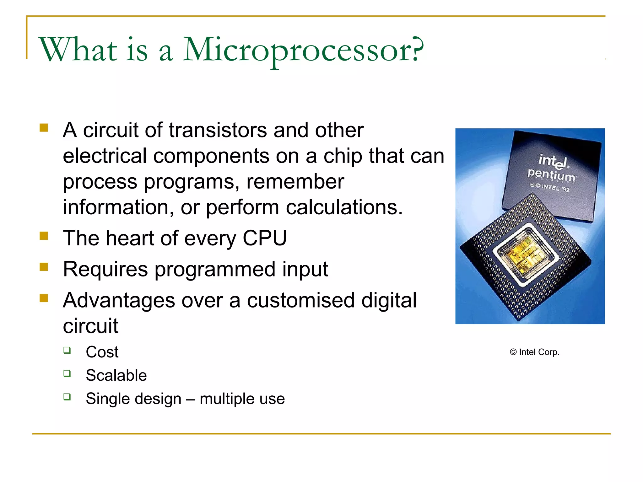
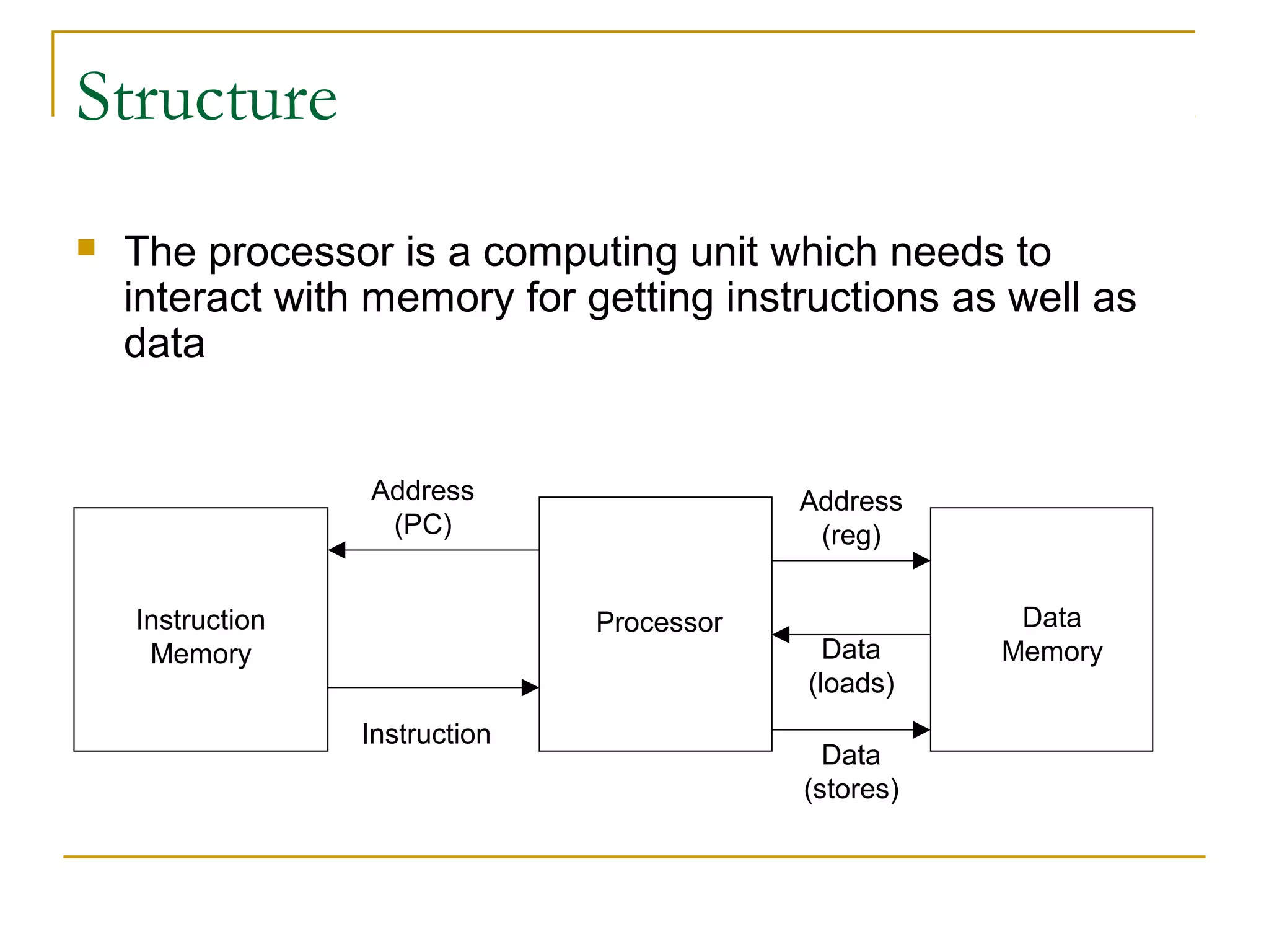
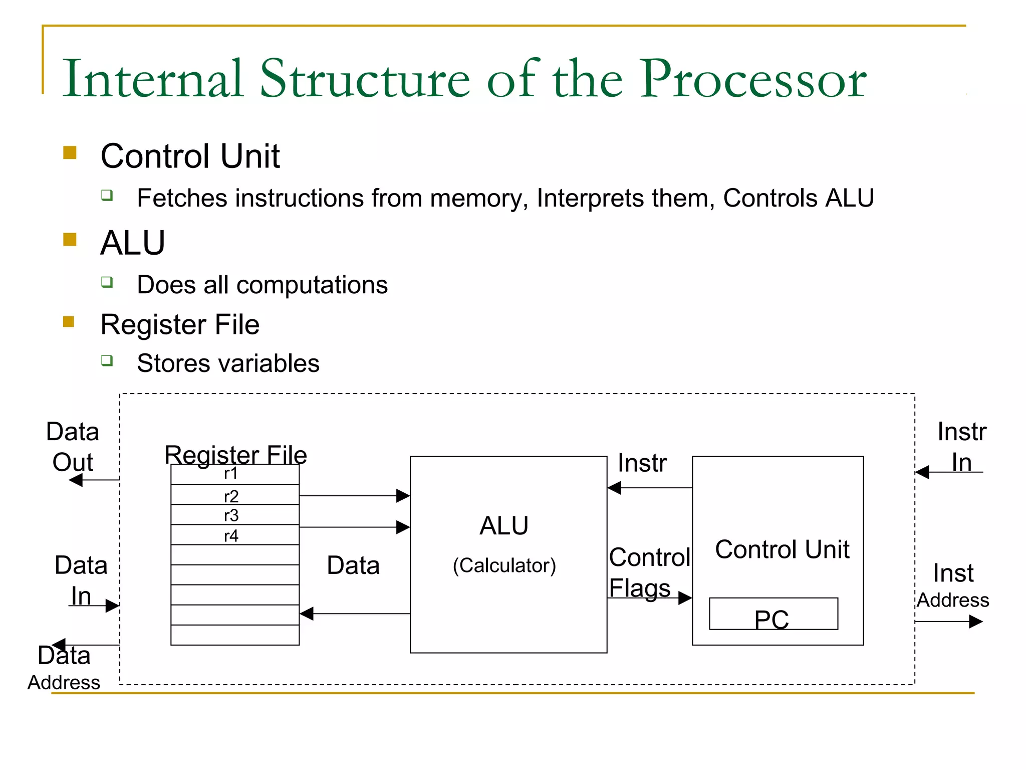
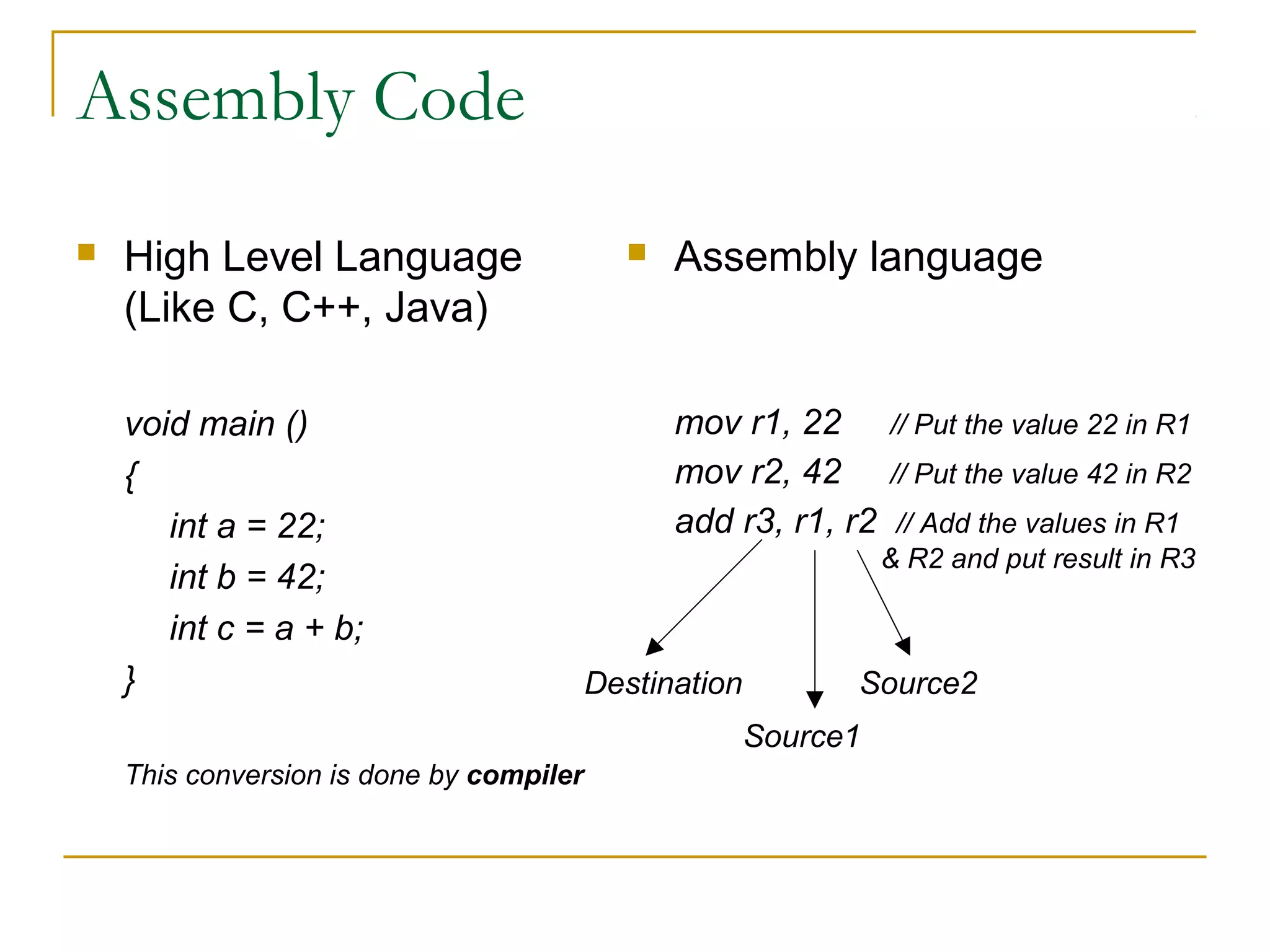
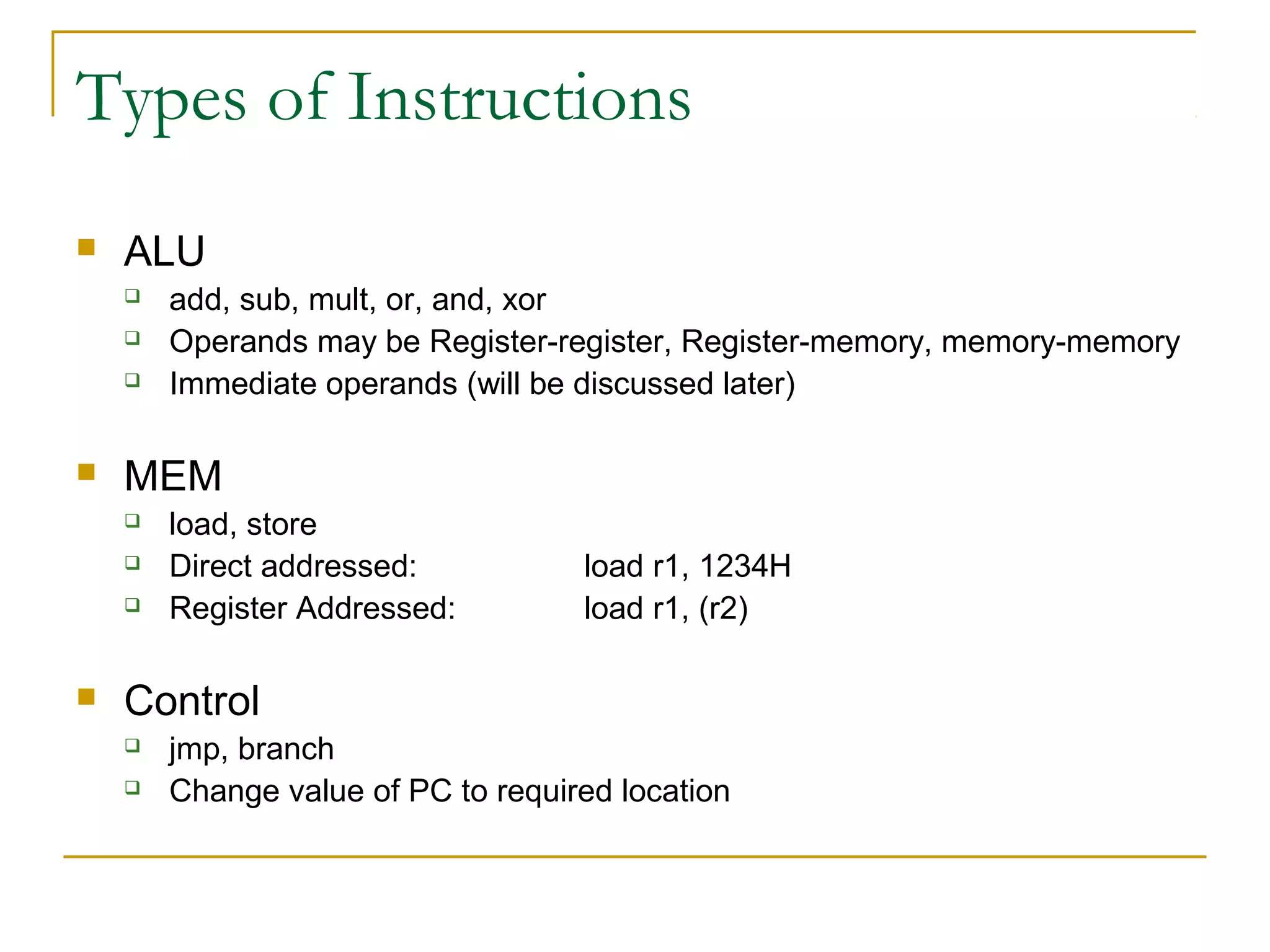
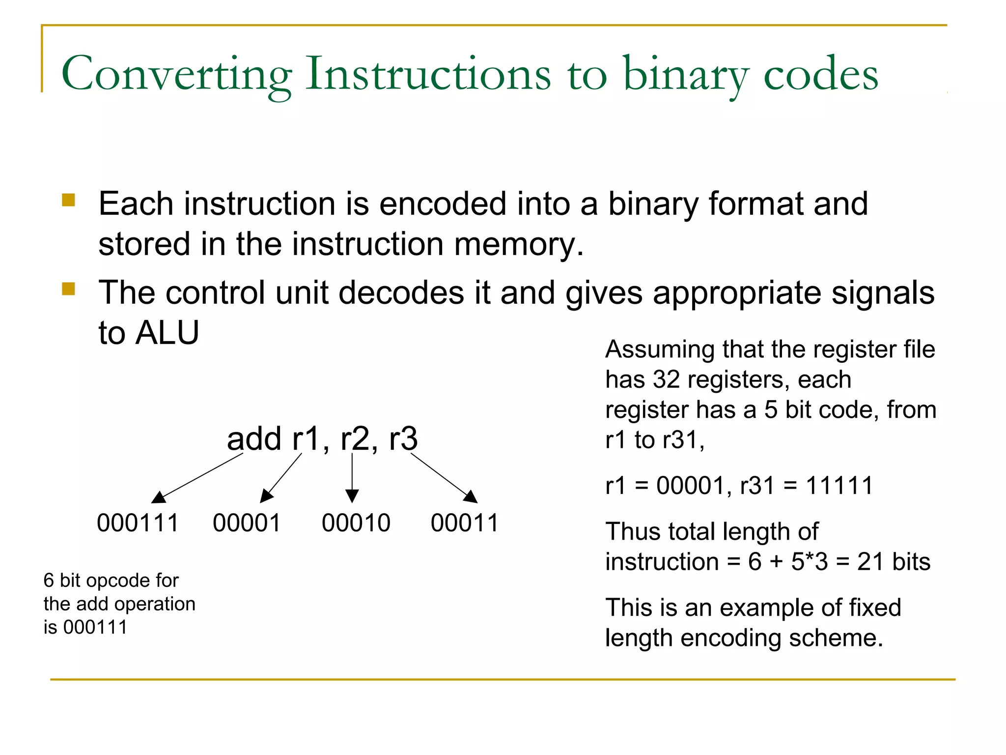
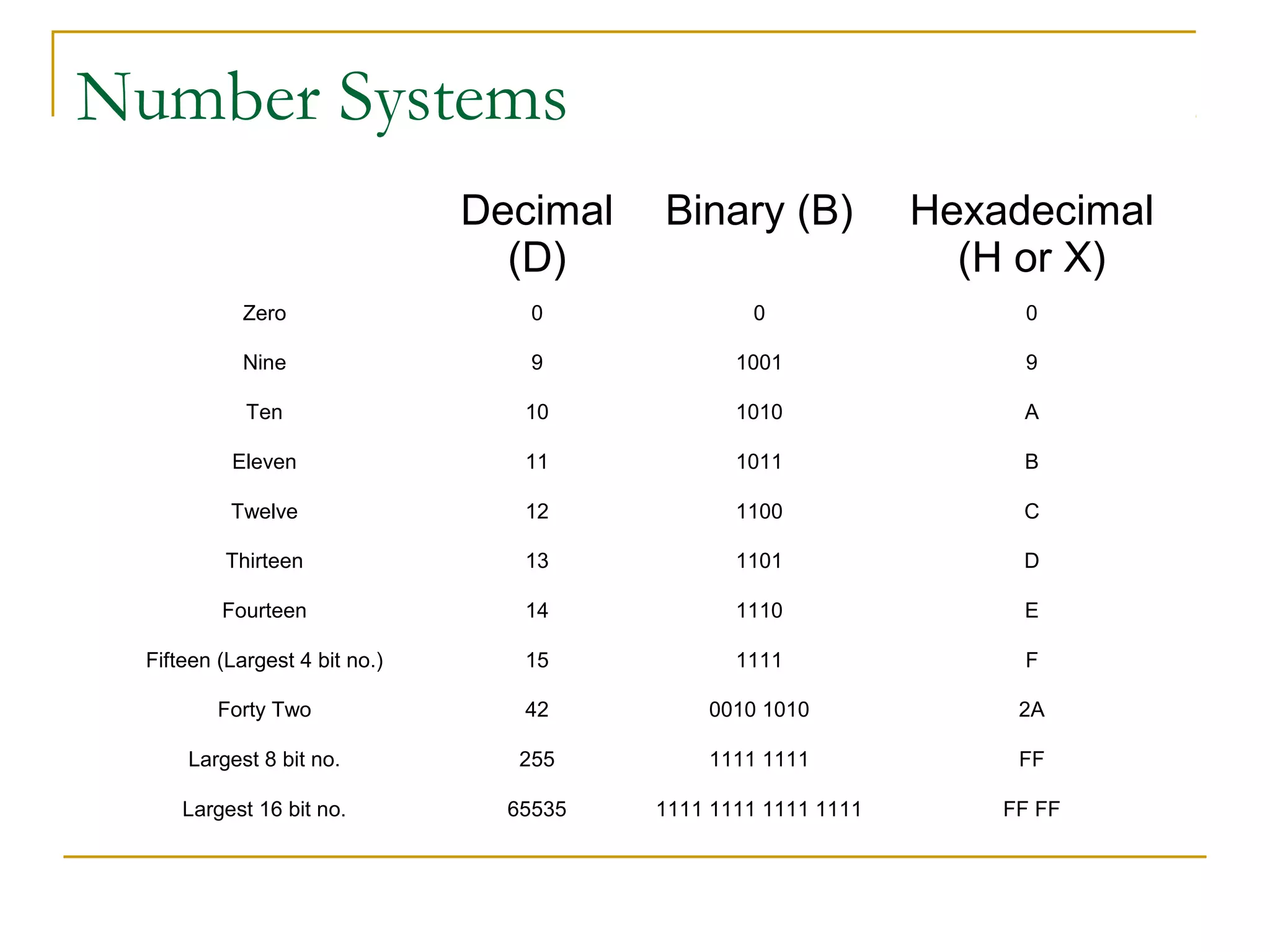
2. Outline
Introduction of a Microprocessor
Microprocessor design objectives and constraints
Structure
Interface
ISA
Microprocessor Instructions
Number Systems
4. Design objectives
Maximize Performance
Speed of operation: How quickly an operation can be completed
Throughput: No of operations completed in unit time, not necessarily
the same as speed, consider Servers.
Maximize Productivity
Interface provided must be easy
Be one step ahead of market needs and two steps
ahead of competition
6. Design Constraints
Power consumed
Today’s processors consume a peak power of 100 W, which means a
peak current of nearly 80A.
Area
Cost
Backward compatibility
Windows running on Intel P3 Processor should run on Intel P4 too.
Time taken to design the processor should not be very
large or else the competitor may get ahead
Other factors like security, scalability, reliability also need
to be considered in processor design
7. Microprocessor Markets
Desktop
Processor for desktop computers. Cost, backward compatibility are very
important. Eg: Intel Pentium, AMD Athlon
Servers
Processor for applications requiring huge amount of computation, data
handling like web servers, database servers, scientific computation
servers. In general, multiple processors are used. Throughput is a very
important metric for servers in general. Eg: Google servers, vsnlproxy
Embedded
For applications in electronic appliances, robots, cars, mobiles etc.
Power consumption, cost are very important metrics. Eg:
Microcontrollers like 8051, PIC, specifically designed processors for cars,
mobiles etc.
8. Structure
The processor is a computing unit which needs to
interact with memory for getting instructions as well as
data
ProcessorInstruction
Memory
Data
Memory
Address
(PC)
Instruction
Address
(reg)
Data
(loads)
Data
(stores)
9. Internal Structure of the Processor
Control Unit
Fetches instructions from memory, Interprets them, Controls ALU
ALU
Does all computations
Register File
Stores variables
Data
Address
ALU
(Calculator)
Register File
Data
Control Unit
Instr
Control
Flags
PC
Data
Out
Data
In
Instr
In
Inst
Address
r1
r2
r3
r4
10. Instruction set architecture (ISA)
The first step in any processor design would be to decide
on an ISA
ISA is the interface provided by the architect to the
external world
The instructions supported with their opcode (The binary representation
of instruction mnemonics)
The width (number of bits) of data, instruction, data address, instruction
address
Other information necessary to the compiler like number of registers in
the register file etc.
11. Assembly Code
High Level Language
(Like C, C++, Java)
void main ()
{
int a = 22;
int b = 42;
int c = a + b;
}
This conversion is done by compiler
Assembly language
mov r1, 22 // Put the value 22 in R1
mov r2, 42 // Put the value 42 in R2
add r3, r1, r2 // Add the values in R1
& R2 and put result in R3
Destination
Source1
Source2
12. Types of Instructions
ALU
add, sub, mult, or, and, xor
Operands may be Register-register, Register-memory, memory-memory
Immediate operands (will be discussed later)
MEM
load, store
Direct addressed: load r1, 1234H
Register Addressed: load r1, (r2)
Control
jmp, branch
Change value of PC to required location
13. Converting Instructions to binary codes
Each instruction is encoded into a binary format and
stored in the instruction memory.
The control unit decodes it and gives appropriate signals
to ALU
add r1, r2, r3
000111 00001 00010 00011
6 bit opcode for
the add operation
is 000111
Assuming that the register file
has 32 registers, each
register has a 5 bit code, from
r1 to r31,
r1 = 00001, r31 = 11111
Thus total length of
instruction = 6 + 5*3 = 21 bits
This is an example of fixed
length encoding scheme.
14. Number Systems
Decimal
(D)
Binary (B) Hexadecimal
(H or X)
Zero 0 0 0
Nine 9 1001 9
Ten 10 1010 A
Eleven 11 1011 B
Twelve 12 1100 C
Thirteen 13 1101 D
Fourteen 14 1110 E
Fifteen (Largest 4 bit no.) 15 1111 F
Forty Two 42 0010 1010 2A
Largest 8 bit no. 255 1111 1111 FF
Largest 16 bit no. 65535 1111 1111 1111 1111 FF FF