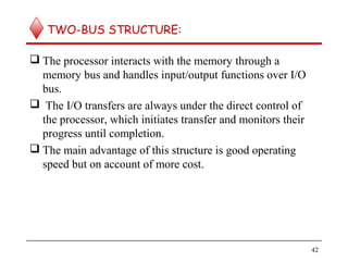
The document provides an overview of computer organization and architecture. It discusses the basic structure of computers including functional units like the CPU, memory, I/O devices, and buses. It covers topics like data and instruction representation, memory operations, interrupts, and bus structures. The document also provides a brief history of computer development from mechanical calculators to modern integrated circuit computers. It defines key concepts like software, system software, and discusses the role of the control unit in coordinating functional units.


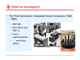


![ E.g. i) R1 [LOC] means that the contents of memory location LOC
are transferred into register R1.
ii) R3 [R1] + [R2] adds the contents of registers R1 and R2
and then places their sum into register R3.
b) Assembly Language Notation:- The same operations can be
represented in assembly language format as shown below.
E.g. i) Move LOC, R1
ii) Add R1,R2,R3
67](https://image.slidesharecdn.com/coa-module1-170527034116/85/Coa-module1-67-320.jpg)

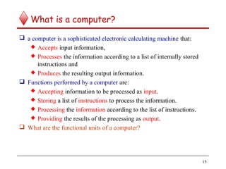
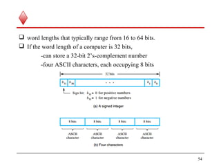
![Three-address instruction
C = A + B is a high level instruction to add the values of the two
variables A and B and to assign the sum to a third variable C.
When this statement is compiled, each of these variables is assigned to
a location in the memory.
The contents of these locations represent the values of the three
variables. Hence the above instruction requires the
Action: C [A] + [B]
69](https://image.slidesharecdn.com/coa-module1-170527034116/85/Coa-module1-69-320.jpg)


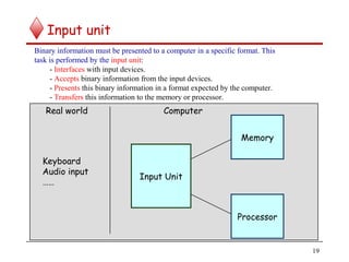
![Two-address instruction
An alternative method is to use two address instruction of the form
Operation Source, Destination
E.g. Add A,B which perform the operation
B [A] + [B]
Here the sum is calculated and the result is stored in location B
replacing the original contents of this location. i.e. operand B acts as
source as well as destination.
72](https://image.slidesharecdn.com/coa-module1-170527034116/85/Coa-module1-72-320.jpg)
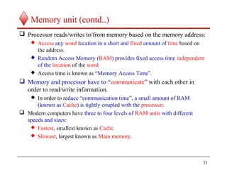
![ In the former case (three address instruction) the contents of A and B
were not destroyed.
But here the contents of B are destroyed. This problem is solved by
using another two-address instruction to copy the contents of one
memory location into another location.
C [A] + [B] is equivalent to
Move B,C
Add A,C
73](https://image.slidesharecdn.com/coa-module1-170527034116/85/Coa-module1-73-320.jpg)

![iii) Store A copies the contents of accumulator to the location A
Depending on the instruction, the operand may be source or
destination.
Now the operation C [A] + [B] can be performed by executing the
following instructions
Load A
Add B
Store C
75](https://image.slidesharecdn.com/coa-module1-170527034116/85/Coa-module1-75-320.jpg)


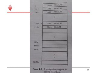
![INSTRUCTIONS EXECUTION AND
STRAIGHT LINE SEQUENCING
Let us take the operation C [A] + [B]. The Example shows the
program segment as it appears in the main memory of a computer that
has a two-address instruction format and a number of general purpose
CPU registers
Example : A program for C [A] + [B]
81](https://image.slidesharecdn.com/coa-module1-170527034116/85/Coa-module1-81-320.jpg)


![ The register used may be a special register provided for this purpose
or may be any one of the general purpose register – referred to as an
Index Register.
Index mode is indicated symbolically as X(Ri), where X denotes a
constant value contained in the instruction and Ri is the name of the
register involved.
The effective address of the operand is given by EA or Aeff = X + [Ri]
In assembly language program, the constant X may be given either as
an explicit number or as a name representing a numerical value.
102](https://image.slidesharecdn.com/coa-module1-170527034116/85/Coa-module1-102-320.jpg)