Download to read offline
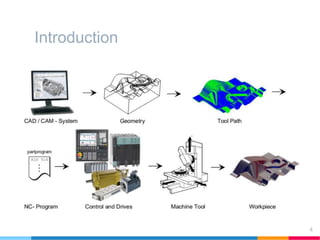
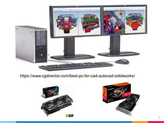
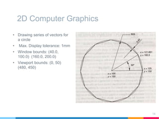
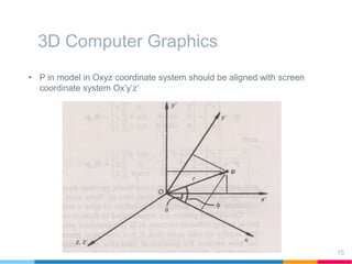
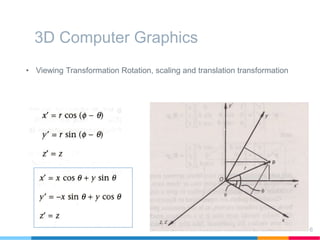
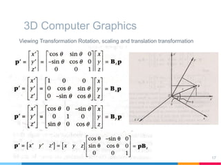
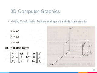
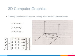
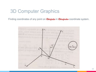
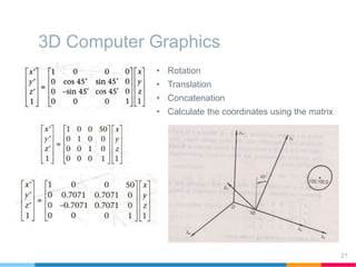


This document discusses elements of interactive computer graphics. It introduces computer graphics types and technologies used for image generation on displays. It describes the steps for displaying 2D and 3D models, which include vectorizing the model, clipping unseen lines, transforming coordinates, and drawing the lines. Key aspects covered include windowing and viewing transformations to map 3D coordinates to 2D screens. The document concludes that low-cost hardware enables high degrees of visual realism when displaying and manipulating engineering models.