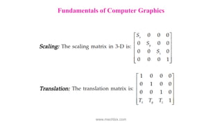
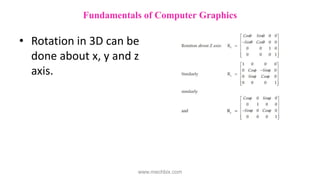
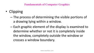
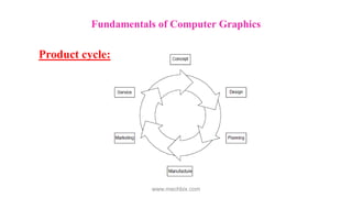
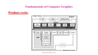
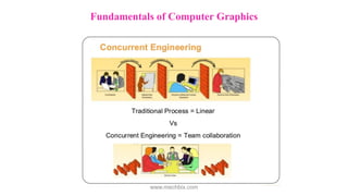
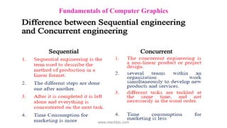
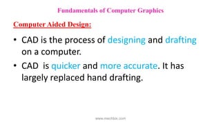
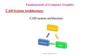
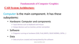
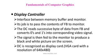
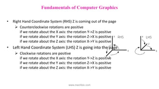
The document discusses fundamentals of computer graphics used in computer aided design. It describes the product design cycle involving design and manufacturing processes. It explains sequential engineering where design, manufacturing, and testing occur sequentially, and concurrent engineering where they overlap. It then covers computer aided design systems, 2D and 3D coordinate systems, and basic 2D transformations like scaling, translation, rotation, and shearing used in CAD modeling.
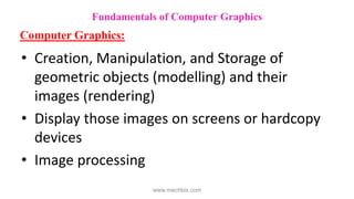
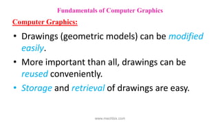
![Example: fig 1 represents a point in the XY
plane, P1(30,20). In the matrix form it is
represented as, P1 = [30 20].
Fundamentals of Computer Graphics
www.mechbix.com](https://image.slidesharecdn.com/cadunit-1-220915045416-98379bc7/85/CAD-Unit-1-pdf-51-320.jpg)
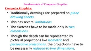
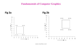
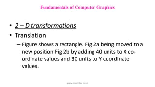
![2 D Transformations
– If we multiply this by a matrix
– We get a new point P2[60
60].
– The matrix is called scaling
matrix.
Figure 1
Fundamentals of Computer Graphics
www.mechbix.com](https://image.slidesharecdn.com/cadunit-1-220915045416-98379bc7/85/CAD-Unit-1-pdf-52-320.jpg)
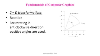
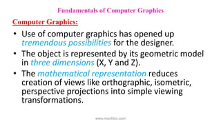
![• The new coordinates are
=
= [14.14 42.42]
Fundamentals of Computer Graphics
www.mechbix.com](https://image.slidesharecdn.com/cadunit-1-220915045416-98379bc7/85/CAD-Unit-1-pdf-61-320.jpg)