Computer Communication Networks- TRANSPORT LAYER PROTOCOLS
•
0 likes•132 views

The document discusses transport layer protocols. It begins by explaining that the transport layer sits between the application and network layers, providing services to applications and receiving services from the network layer. It then notes that the three major transport layer protocols are UDP, TCP, and SCTP. UDP provides a simple, unreliable connectionless service. TCP provides a reliable, connection-oriented service through mechanisms like flow and error control. SCTP combines features of UDP and TCP, providing both connection-oriented and connectionless services.

More Related Content
What's hot
What's hot (20)
Similar to Computer Communication Networks- TRANSPORT LAYER PROTOCOLS
Similar to Computer Communication Networks- TRANSPORT LAYER PROTOCOLS (20)
More from Krishna Nanda
More from Krishna Nanda (16)
Recently uploaded
Recently uploaded (20)
Computer Communication Networks- TRANSPORT LAYER PROTOCOLS
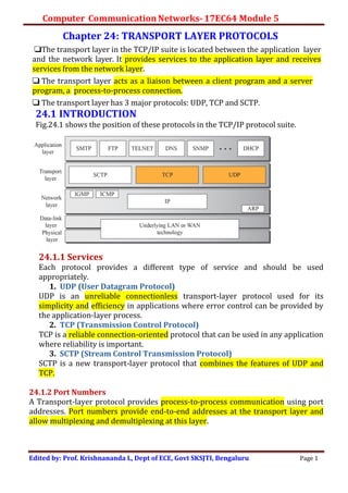
- 1. Computer Communication Networks-17EC64 Module 5 Edited by: Prof. Krishnananda L, Dept of ECE, Govt SKSJTI, Bengaluru Page 1 Chapter 24: TRANSPORT LAYER PROTOCOLS ❑The transport layer in the TCP/IP suite is located between the application layer and the network layer. It provides services to the application layer and receives services from the network layer. ❑ The transport layer acts as a liaison between a client program and a server program, a process-to-process connection. ❑ The transport layer has 3 major protocols: UDP, TCP and SCTP. 24.1 INTRODUCTION Fig.24.1 shows the position of these protocols in the TCP/IP protocol suite. 24.1.1 Services Each protocol provides a different type of service and should be used appropriately. 1. UDP (User Datagram Protocol) UDP is an unreliable connectionless transport-layer protocol used for its simplicity and efficiency in applications where error control can be provided by the application-layer process. 2. TCP (Transmission Control Protocol) TCP is a reliable connection-oriented protocol that can be used in any application where reliability is important. 3. SCTP (Stream Control Transmission Protocol) SCTP is a new transport-layer protocol that combines the features of UDP and TCP. 24.1.2 Port Numbers A Transport-layer protocol provides process-to-process communication using port addresses. Port numbers provide end-to-end addresses at the transport layer and allow multiplexing and demultiplexing at this layer.
- 2. Computer Communication Networks-17EC64 Module 5 Edited by: Prof. Krishnananda L, Dept of ECE, Govt SKSJTI, Bengaluru Page 2 24.2 USER DATAGRAM PROTOCOL (UDP) It is a connectionless, unreliable transport layer protocol, providing process- to-process communication. UDP is a very simple protocol using a minimum of overhead. If a process wants to send a small message and reliability is not an issue, it can use UDP.Sending a small message using UDP takes much less interaction between the sender and receiver than using TCP. 24.2.1 User Datagram UDP packets, called user datagrams, have a fixed-size header of 8 bytes. Fig.24.2 shows the format of user datagram.
- 3. Computer Communication Networks-17EC64 Module 5 Edited by: Prof. Krishnananda L, Dept of ECE, Govt SKSJTI, Bengaluru Page 3 The Header has a fixed size of 8 bytes made of 4 fields, each of 2 bytes. The fields are: i) source port number (16 bits) ii) destination port number (16 bits) iii) Total length (16 bits) – defines size of user datagram. Max 65535 bytes, but usually smaller than this iv) Header checksum (16 bits) Example 24.1 The following is the content of a UDP header in hexadecimal format. CB84000D001C001C a. What is the source port number? b. What is the destination port number? c. What is the total length of the user datagram? d. What is the length of the data? e. Is the packet directed from a client to a server or vice versa? f. What is the client process? Solution a. The source port number is the first four hex digits (CB84)16 = 52100d i.e., source port number is 52100. b. The destination port number is the second four hex digits (000D)16 =13d, i.e., the destination port number is 13. c. The third four hex digits (001C)16 defines the length of the whole UDP packet. So, length is (001C)16 = 28 bytes. d. Length of data = Total length – header length = 28-8 = 20bytes e. Since the destination port number is 13 (well-known port), the packet is from the client to the server. f. The client process is the Daytime (see Table 24.1). 24.2.2 UDP Services Process-to-Process Communication UDP provides process-to-process communication using socket addresses, a combination of IP addresses and port numbers. Connectionless Services UDP provides a connectionless service. i.e., each user datagram sent by UDP is an independent datagram, even if they are coming from the same source process and going to the same destination program. The user datagrams are not numbered. Also, unlike TCP, there is no connection establishment and no connection termination. This means that each user datagram can travel on a different path. Flow Control UDP is a very simple protocol. There is no flow control, and hence no window mechanism. The receiver may overflow with incoming messages.
- 4. Computer Communication Networks-17EC64 Module 5 Edited by: Prof. Krishnananda L, Dept of ECE, Govt SKSJTI, Bengaluru Page 4 Error Control There is no error control mechanism in UDP except for the checksum. i.e., the sender does not know if a message has been lost orduplicated. When the receiver detects an error through the checksum, the user datagram is discarded. Checksum UDP checksum calculation includes three sections: A pseudoheader, the UDP header, and the data coming from the application layer. The pseudoheader is the part of the header of the IP packet in which the user datagram is to be encapsulated with some fields filled with 0s The protocol field is added to ensure that the packet belongs to UDP, and not toTCP. The value of the protocol field for UDP is 17. If this value is changed during transmission, the checksum calculation at the receiver will detect it and UDP drops the packet. It is not delivered to the wrong protocol Congestion Control Since UDP is a connectionless protocol, it does not provide congestion control. UDP assumes that the packets sent are small and sporadic and cannot create congestion in the network. (However, when UDP is used for interactive real- time transfer of audio and video, may lead to congestion). Encapsulation and Decapsulation To send a message from one process to another, the UDP protocol encapsulates and decapsulates messages. Queuing In UDP, queues are associated with ports. At the client site, when a process starts, it requests a port number from the operating system. We may create both an incoming and an outgoing queue associated with each process.
- 5. Computer Communication Networks-17EC64 Module 5 Edited by: Prof. Krishnananda L, Dept of ECE, Govt SKSJTI, Bengaluru Page 5 24.2.3 UDP Applications UDP Features: Connectionless Service UDP is a connectionless protocol. Each UDP packet is independent from other packets sent by the same application program. i.e., UDP does not recognize any relationship between the datagrams. UDP can be used for ex, a client application needs to send a short request to a server and to receive a short response. If the request and response can each fit in a single user datagram, a connectionless service may be preferable. The connectionless service provides less delay. If providing fast response is more important than reliable operation, UDP is preferred. A client-server application like DNS uses the services of UDP. Not suitable for Email, File transfer etc Lack of Error Control UDP does not provide error control; it provides an unreliable service. . Lack of Congestion Control UDP does not provide for congestion control. However, since there is no retransmission, UDP does not add to the congestion in the network. So, its an advantage inan error-prone network. Typical Applications The following shows some typical applications that can benefit more from the services of UDP than from those of TCP. ❑ UDP is suitable for a process that requires simple request-response communication with little concern for flow and error control. It is not usually used for a process suchas FTP that needs to send bulk data. ❑ UDP is suitable for a process which has built-in flow- and error-control mechanisms. For ex, Trivial File Transfer Protocol (TFTP) process uses UDP. ❑ UDP is a suitable transport protocol for multicasting. Multicasting capability is embedded in the UDP software but not in the TCP software. ❑ UDP is used for management processes such as SNMP ❑ UDP is used for some route updating protocols such as RIP ❑ UDP is normally used for interactive real-time applications that cannot tolerate uneven delay between sections of a received message
- 6. Computer Communication Networks-17EC64 Module 5 Edited by: Prof. Krishnananda L, Dept of ECE, Govt SKSJTI, Bengaluru Page 6 24.3 Transmission Control Protocol (TCP) Transmission Control Protocol (TCP) is a connection-oriented, reliable protocol. TCP explicitly defines connection establishment, data transfer, and connection teardown phases to provide a connection-oriented service. TCP uses a combination of GBN and SR protocols to provide reliability. 24.3.1 TCP Services 1. Process-to-Process communication TCP provides process-to-process communication using port numbers. 2. Stream Delivery Service TCP is a stream-oriented protocol. (UDP is not) TCP allows the sending process to deliver data as a stream of bytes and allows the receiving process to obtain data as a stream of bytes. TCP creates an environment in which the two process seem to be connected by an imaginary “tube” that carries their bytes across the Internet. (Fig.24.4) Sending process produces (writes to) the stream and receiving process consumes (reads from) the stream. 3. Sending and Receiving Buffers The sending and the receiving processes may not write or read data at the same rate. So, TCP needs two buffers (sending and receiving) for storage. These buffers are also necessary for flow- and error-control mechanisms used by TCP. One way to implement a buffer is to use a circular array of 1-byte locations as shown in Fig. 24.5. (Ex: two buffers of 20 bytes each). Both buffers need not be of same size. Fig. shows the movement of the data in one direction. At the sender, the buffer has three types of chambers. The white section contains empty chambers that can be filled by the sending process (producer). The Yellow region contains bytes to be sent by the sending TCP. The Blue region holds bytes that have been sent but not yet acknowledged. After the bytes in the Blue region are acknowledged, the chambers are recycled and available for use by the sending process. At the receiver, the circular buffer is divided into two areas. The white area contains empty chambers to be filled by bytes received from the network. The
- 7. Computer Communication Networks-17EC64 Module 5 Edited by: Prof. Krishnananda L, Dept of ECE, Govt SKSJTI, Bengaluru Page 7 colored section contains received bytes that can be read by the receiving process. When a byte is read by the receiving process, the chamber is recycled and added to the pool of empty chambers. Fig.24.5 Sending and Receiving Buffers 4. TCP Segments The network layer, as a service provider for TCP, needs to send data in packets, (not as a stream of bytes). At the transport layer, TCP groups a number of bytes together into a packet called a Segment. TCP adds a header to each segment and delivers the segment to the network layers for transmission. The segments are encapsulated in an IP datagram and transmitted. These IP datagrams (containing TCP segments) may follow different physical paths through the network, may be received out of order, lost or corrupted, and resent. These issues are handled by TCP receiver. Since TCP provides stream oriented service, receiver TCP ensures to deliver the bytes in order to the application layer. Fig. 24.6 shows how segments are created from the bytes in the buffers. All Segments need not contain same number of bytes. 5. Full-Duplex Communication TCP offers full-duplex service, where data can flow in both directions at the same time. Each TCP endpoint then has its own sending and receiving buffer, and segments move in both directions.
- 8. Computer Communication Networks-17EC64 Module 5 Edited by: Prof. Krishnananda L, Dept of ECE, Govt SKSJTI, Bengaluru Page 8 6. Multiplexing and De-multiplexing Like UDP, TCP performs multiplexing at the sender and demultiplexing at the receiver. However, a connection needs to established for each pair of processes. 7. Connection-Oriented Service TCP is a connection-oriented protocol. When a process at site A wants to send to and receive data from another process at site B, the following three phases occur: 1. The two TCP’s establish a logical connection between them. 2. Data are exchanged in both directions. 3. The connection is terminated. 8. Reliable service TCP is a reliable transport protocol. It uses an acknowledgement mechanism to check the safe and sound arrival of data 24.3.2 TCP Features Numbering Systems Although the TCP software keeps track of the segments being transmitted or received, there is no field for a segment number value in the segment header. Instead, there are two fields: the sequence number and the ACK number. These two fields refer to a byte number and not a segment number. 1.Byte Number TCP numbers all data bytes (octets) that are transmitted in a connection. Numbering is independent in each direction. When TCP receives bytes of data from a process, TCP stores them in the sending buffer and numbers them. TCP chooses an arbitrary number between 0 and 232-1 for the number of first byte. 2. Sequence Number After the bytes have been numbered, TCP assigns a sequence number to each segment. The sequence number, in each direction, is defined as follows: i. The sequence number of the first segment is the ISN (initial sequence number), which is a random number (need not be zero). ii. The sequence number of any other segment is the sequence of the previous segment plus the number of bytes (real or imaginary) carried by the previous segment. Note: Communication in TCP is full-duplex, i.e., both parties can send and receive at the same time. The sequence number in each direction shows the number of the first byte carried by the segment. 3. Acknowledgment Number Each party uses an ACK number to confirm the bytes it has received. The ACK number defines the number of the next byte that the party expects to receive.
- 9. Computer Communication Networks-17EC64 Module 5 Edited by: Prof. Krishnananda L, Dept of ECE, Govt SKSJTI, Bengaluru Page 9 The ACK number is cumulative, which means that the party takes the number of the last byte that it has received, adds 1 to it and this sum is the ACK number. The term cumulative means that if a party uses 4567 as an ACK number, it has received all bytes from the beginning up to 4566. 24.3.3 TCP Segment Format. A Packet in TCP is called as a segment. The segment consists of a header of 20 to 60 bytes followed by data from Application layer. Fig.24.7 shows TCP segment format. The fields of the TCP Header are: i. Source Port Address (16 bits): defines the port number of the application program of the source. ii. Destination Port Address (16 bits): defines the port number of the application program of the destination. iii. Sequence Number (32-bits): defines the number assigned to the first byte of data contained in this segment. Each byte to be sent is numbered by the source. iv. Acknowledgment Number (32-bits): defines the byte number that the receiver is expecting to receive next. If receiver has received byte number x from the sender, its sends an ACK with number x+1. v. HLEN (4 bits): indicates the TCP header length as multiple of 4-bytes. HLEN min value is 5d & max value is 15d. Header length in bytes = HLEN value x 4. vi. Control field (6 bits): 6 different control flags, which enables flow control, connection establishment and termination, mode of operation etc,.
- 10. Computer Communication Networks-17EC64 Module 5 Edited by: Prof. Krishnananda L, Dept of ECE, Govt SKSJTI, Bengaluru Page 10 vii. Window Size (16-bits): defines the window size of the sending TCP in bytes. Maximum size of the window is 216-1 i.e,. 65535 bytes and is normally referred to as receiving window (rwnd) and is determined by the receiver. viii. Checksum (16 bits): use of Checksum in TCP is mandatory. Uses a pseudoheaer. ix. Urgent Pointer (16 bits): This field that is valid only if URG flag is set. It is used when segment contains urgent data. x. Options (0 to 40 bytes): optional information Control field in detail: Checksum using Pseudoheader: 24.3.4.TCP Connection TCP is connection-oriented, creating a logical path between source and destination. All the segments belonging to a message are then sent over this logical path. This helps in getting ACKs as well as retransmission of damaged or lost segments. If segments arrive out-of-order, receiver TCP holds them until all segments arrive, rearranges them in order and then only delivers to the application process. In TCP, communication requires 3 phases.
- 11. Computer Communication Networks-17EC64 Module 5 Edited by: Prof. Krishnananda L, Dept of ECE, Govt SKSJTI, Bengaluru Page 11 1. Connection Establishment (using 3 ways handshaking). 2. Data Transfer. 3. Connection termination (using 3 ways handshaking). 1.Connection Establishment using three-way Handshaking TCP transmits data in full-duplex mode. i.e., each party is able to send segments to other simultaneously. So, each party must initialize communication and get approval from the other party before any data are transferred Three-Way Handshaking The connection establishment in TCP is called three-way handshaking. Consider the scenario: an application program, called the client, wants to make a connection with another application program, called the server, using TCP as the transport- layer protocol. Initiation happens from the server. The server program tells its TCP that it is ready to accept a connection. This request is called a passive open. However, it cannot make the connection itself. A client that wishes to connect to an open server tells its TCP to connect to a particular server and issues a request for an active open. TCP can now start the three-way handshaking process, as shown in Fig.24.10. Note: Each segment has values for all its header. However, we show only few fields: the sequence number, the ACK number, the control flags (only those that are set), and window size if relevant. The three steps in this phase are: i. The client sends the first segment, a SYN segment (only the SYN flag is set). for synchronization of sequence numbers. The client chooses a random number as the first sequence number and sends this number to the server. This sequence number is called the initial sequence number (ISN). The SYN segment is a control segment and carries no data. However, it consumes one sequence number because it needs to be acknowledged. We can say that the SYN segment carries one imaginary byte. ii. The server sends the second segment, a SYN + ACK segment with two flag bits set as: SYN and ACK. It serves a dual purpose. a) The server uses this SYN segment to initialize a sequence number for numbering the bytes to be sent from the server to the client. b) The server also acknowledges the receipt of the SYN segment from the client by setting the ACK flag and displaying the next sequence number it expects to receive from the client. Because the segment contains an ACK, it also needs to define the receive window size, rwnd (to be used by the client). This SYN+ACK segment consumes one sequence number. iii. The client sends the third segment. This is just an ACK segment. It acknowledges the receipt of the second segment with the ACK flag and ACK number field. ACK segment does not consume any sequence numbers if it does not carry data.
- 12. Computer Communication Networks-17EC64 Module 5 Edited by: Prof. Krishnananda L, Dept of ECE, Govt SKSJTI, Bengaluru Page 12 2. Data Transfer After connection is established, bidirectional data transfer takes place. The client and server can send data and ACK in both directions. The ACK is piggybacked with data. Consider that the client sends 2000 bytes of data in two segments and the server then sends 2000 bytes in one segment. The client then sends one more segment. The first 3 segments carry both data and ACK, but the last segment carries only an ACK because it has no more data to be sent. Fig.24.11 shows the scenario. Generally, TCP uses buffering at both the ends to provide flow control and flexibility. However, due to buffering, data transmission and delivery may be delayed, which is not suitable for interactive communication. In such a case, application at the sender can request a Push operation. So, client TCP creates a segment and sends it immediately and sets the PSH (push) flag in the data segments sent. So, the server TCP can deliver the data to the server process as soon as they are received. TCP is a stream-oriented protocol. i.e., data is a stream of bytes and each byte has a position in the stream. However, an application may require some bytes to be treated in a special way. So, sending (client) TCP creates a segment with URG (urgent) flag set and inserts the urgent data at the start of the segment. The “urgent pointer” field in the header defines the end of urgent data. The receiving TCP informs the application program about the beginning and end of urgent data.
- 13. Computer Communication Networks-17EC64 Module 5 Edited by: Prof. Krishnananda L, Dept of ECE, Govt SKSJTI, Bengaluru Page 13 Fig.24.11 Data Transfer using TCP 3. Connection Termination Either of the two parties (client or server) can close the connection. Can be done two ways: Three-way handshaking and four-way handshaking with half-close option. Three-Way Handshaking Three-way handshaking for connection termination is shown in Figure 24.12. 1. The client TCP, after receiving a close command from the client process, sends a FIN segment with FIN flag set. A FIN segment can include the last chunk of data sent by the client or it can be just a control segment. FIN segment consume one sequence number if it does not carry data. 2. The server TCP after receiving the FIN segment, sends a FIN + ACK segment to confirm the receipt of the FIN segment from the client and at the same time to announce the closing of the connection in the other direction. This segment can also contain the last chunk of data from the server. If it does not carry data, it consumes only one sequence number. 3. The client TCP sends the last segment, an ACK segment, to confirm the receipt of the FIN segment from the TCP server. This segment contains the ACK number, which is one more than the sequence number received in the FIN segment from the server. This segment cannot carry data and consumes no sequence numbers.
- 14. Computer Communication Networks-17EC64 Module 5 Edited by: Prof. Krishnananda L, Dept of ECE, Govt SKSJTI, Bengaluru Page 14 . Half-close Operation: One end (client or server) can stop sending data while it is still receiving data. This situation is called half-close. For ex., after sending all the data to a server for computation, client can half-close the connection (i.e., from client-to-server) by sending a FIN segment. The server accepts it by sending the ACK. Now, client cannot send any more data to the server. After the computation is over, server can send the results to client. After sending all the processed data to client, server sends a FIN segment which is acknowledged by and ACK from the client. The half-close operation is depicted in Fig. 24.13. Connection Reset TCP at one end may deny a connection request, may abort an existing connection, or may terminate an idle connection. All of these are done with the RST (reset) flag.
- 15. Computer Communication Networks-17EC64 Module 5 Edited by: Prof. Krishnananda L, Dept of ECE, Govt SKSJTI, Bengaluru Page 15 SYN Flooding Attack The connection establishment procedure in TCP is susceptible to a serious security problem called SYN flooding attack. This happens when one or more malicious attackers send a large number of SYN segments to a server pretending that each of them is coming from a different client by faking the source IP addresses in the datagrams. The server, assuming that the clients are issuing an active open, allocates the necessary resources, such as creating transfer control block (TCB) tables and setting timers. The TCP server then sends the SYN + ACK segments to the fake clients, which are lost. If the number of SYN segments is large, the server may run out of resources and may be unable to accept connection requests from valid clients. This SYN flooding attack belongs to a category known as a denial of service (DOS) attack, in which an attacker monopolizes a system with so many service requests that the system overloads and denies service to valid requests. Solution: 1) Restrict the number of connection requests during a specified period of time. 2) Filter out datagrams coming from unwanted source addresses. 3) Postpone resource allocation until the server can verify that the connection request is coming from a valid IP address, by using what is called a cookie. SCTP uses this strategy.
- 16. Computer Communication Networks-17EC64 Module 5 Edited by: Prof. Krishnananda L, Dept of ECE, Govt SKSJTI, Bengaluru Page 16 24.3.5 State Transition Diagram TCP is specified as a finite state machine (FSM). The round corner rectangles represents the states. Directed lines represents the state transition. Each line has two strings separated by a slash. The first string is the input (what TCP receives) the second is the output (what TCP sends) Dotted line represents the transition done by the server. Solid line represents the transition done by the client. Colored lines show special situations. Table 24.2 shows the states of TCP. TCP state diagram and transitions can be explained taking an example of Half-close scenario, as shown in Fig. 24.15
- 17. Computer Communication Networks-17EC64 Module 5 Edited by: Prof. Krishnananda L, Dept of ECE, Govt SKSJTI, Bengaluru Page 17 Explanation: Step 1: The server process issues a passive open command. The server TCP goes to the LISTEN state and remains there passively until it receives a SYN segment from client. Step 2: The client process issues an active open command to its TCP to request a connection to a specific socket address. Client TCP sends a SYN segment and moves to the SYN-SENT state. Step 3: The server TCP sends a SYN + ACK segment and goes to the SYN-RCVD state, waiting for the client to send an ACK segment. Step 4: After receiving the SYN + ACK segment, client TCP sends an ACK segment and goes to the ESTABLISHED state. Step 5: After receiving the ACK segment, server TCP also goes to the ESTABLISHED state. Now, data are transferred, possibly in both directions, and acknowledged. Step 6: When the client process has no more data to send, it issues a command called an active close. The client TCP sends a FIN segment and goes to the FIN- WAIT-1 state. Step 7: The server, upon receiving the FIN segment, sends an ACK segment to the client and goes to the CLOSE-WAIT state. Step 8: When client receives the ACK segment, it goes to the FIN-WAIT-2 state. Step 9: After receiving the passive close command from its application layer, the server sends a FIN segment to the client and goes to the LAST-ACK state, waiting for the final ACK from the client. Step 10: When the client receives a FIN segment, it sends an ACK segment and goes to the TIME-WAIT state. The client remains in this state for 2 MSL seconds When the corresponding timer expires, the client goes to the CLOSED state. Step 11: When the ACK segment is received from the client, the server goes to the CLOSE state.
- 18. Computer Communication Networks-17EC64 Module 5 Edited by: Prof. Krishnananda L, Dept of ECE, Govt SKSJTI, Bengaluru Page 18 24.3.6 WINDOWS IN TCP ▪ TCP uses two windows (Send and Receive window) for each direction of data transfer. So, there will be 4 windows for a bidirectional communication. ▪ Let us assume unidirectional communication (say from client to server). 1) Send Window: The window size is say, 100 bytes. Fig.24.17 shows how a send window opens, closes, or shrinks. The send window in TCP is similar to the window in SR protocol with some differences: 1. Window size in TCP is the number of bytes. The variables that control the window are expressed in bytes. 2. We assume that the sending TCP is capable of sending segments of data as soon as it receives them from its process (no buffering) 3. The TCP protocol uses only one timer. Fig.24.17 Send Window in TCP 2) Receive Window Fig. 24.18 shows an example of a receive window. The window size is 100 bytes. There are two differences between the receive window in TCP and the one we used for SR. 1. TCP allows the receiving process to pull data whenever it needs that data. Receiver buffer may have bytes that have been received and acknowledged, but are waiting to be pulled by the receiving process. The receive window size is then smaller than or equal to the buffer size, as shown in Fig. The
- 19. Computer Communication Networks-17EC64 Module 5 Edited by: Prof. Krishnananda L, Dept of ECE, Govt SKSJTI, Bengaluru Page 19 receive The receiver window size, normally called rwnd, can be determined as: rwnd = buffer size – number of bytes waiting to be pulled 2. An ACK in SR is selective, defining the uncorrupted packets that have been received. The major ACK mechanism in TCP is a cumulative ACK announcing the next expected byte to receive. The new version of TCP, however uses both cumulative and selective acknowledgments. Fig.24.18 Receive window in TCP 24.3.7 FLOW CONTROL Flow control Balances the rate a producer creates data with the rate a consumer can use the data. Assume an error free channel between sending and receiving TCP. Fig 24.19 shows unidirectional data transfer between a sender and a receiver. Fig 24.19 shows that data travel from the sending process to sending TCP, from the sending TCP to the receiving TCP and from the receiving TCP to receiving process (paths 1,2,3). Flow control feedbacks are travelling from the receiving TCP to the sending TCP and from the sending TCP up to the sending process (paths 4 and 5). The receiving TCP controls the sending TCP; The sending TCP controls the sending process.
- 20. Computer Communication Networks-17EC64 Module 5 Edited by: Prof. Krishnananda L, Dept of ECE, Govt SKSJTI, Bengaluru Page 20 1) Opening and Closing Windows To achieve flow control, TCP forces the sender and the receiver to adjust their window sizes. The receive window closes (moves its left wall to the right) when more bytes arrive from the sender; it opens (moves its right wall to the right) when more bytes are pulled by the process. The opening, closing, and shrinking of the send window is controlled by the receiver. The send window closes (moves its left wall to the right) when a new ACK allows it to do so. The send window opens (its right wall moves to the right) when the receive window size (rwnd) advertised by the receiver allows it to do so. (new ackNo + new rwnd > last ackNo + last rwnd) 2) Silly Window Syndrome A serious problem arises in the sliding window operation when either the sending application program creates data slowly or the receiving application program consumes data slowly, or both. Any of these situations results in the sending of data in very small segments, which reduces the efficiency of the operation. This problem is called the silly window syndrome. a) Syndrome Created by the Sender The sending TCP may create a silly window syndrome if the application program creates data slowly. For ex, let the application program write 1 byte at a time into the buffer of the sender TCP. If TCP sends segments containing only 1 byte of data, it means that a 41-byte datagram (20 bytes of TCP header and 20 bytes of IP header) transfers only 1 byte of user data. Here the overhead is 41/1. i.e, just to send 1 byte of user data we are actually sending 41 bytes on the network. So, we are using the capacity of the network very inefficiently. The inefficiency is even worse if we account for the data-link layer and physical-layer overhead. One solution is that sending TCP must wait & collect data from application so that it can send data in larger blocks, instead of few bytes. Too long waiting time may delay the process. Less waiting time means, TCP may send only small segments. To have a balance, Nagle proposed the following:
- 21. Computer Communication Networks-17EC64 Module 5 Edited by: Prof. Krishnananda L, Dept of ECE, Govt SKSJTI, Bengaluru Page 21 Nagle’s Algorithm: 1. The sending TCP sends the first piece of data it receives from the sending application program even if it is only 1 byte. 2. After sending the first segment, the sending TCP accumulates data in the output buffer and waits until either the receiving TCP sends an ACK or until enough data have accumulated to fill a maximum-size segment. At this time, the sending TCP can send the segment. 3. Step 2 is repeated for the rest of the transmission. Segment 3 is sent immediately if an ACK is received for segment 2, or if enough data have accumulated to fill a maximum-size segment It takes care of both: speed of Application pgm as well as speed of the network. b) Syndrome Created by the Receiver The receiving TCP may create a silly window syndrome if it is serving an application program that consumes data slowly than they arrive. Suppose that the sending application program creates data in blocks of 1 KB, but the receiving application program consumes data 1 byte at a time. One byte of data is consumed and a segment carrying 1 byte of data is sent. Again we have an efficiency problem and the silly window syndrome. Solution: 1) Clark’s solution is to send an ACK as soon as the data arrive, but to announce a window size of zero until either there is enough space to accommodate a segment of maximum size or until at least half of the receive buffer is empty. 2) The second solution is to delay sending the ACK. i.e., when a segment arrives, it is not acknowledged immediately. The receiver waits until there is a decent amount of space in its incoming buffer before acknowledging the arrived segments. The delayed ACK prevents the sending TCP from sliding its window. After the sending TCP has sent the data in the window, it stops. This kills the syndrome. Delayed ACK also has another advantage: it reduces traffic. The receiver does not have to acknowledge each segment. However, the sender may be unnecessarily retransmitting the unacknowledged segments. For this, we can fix a threshold, for ex., the ACK should not be delayed by more than 500 ms. 24.3.8 ERROR CONTROL Error control in TCP can be achieved using 3 simple tools in TCP. Checksum, Acknowledgement (Cumulative ACK/ Selective ACK) and Time out. a) Checksum Each segment includes a checksum field, which is used to check for a corrupted segment. If a segment is corrupted, as detected by an invalid checksum, the segment is discarded by the destination TCP and is considered as lost. TCP uses a 16-bit checksum that is mandatory in every segment.
- 22. Computer Communication Networks-17EC64 Module 5 Edited by: Prof. Krishnananda L, Dept of ECE, Govt SKSJTI, Bengaluru Page 22 b) Acknowledgment TCP uses acknowledgments to confirm the receipt of data segments. Control segments that carry no data, but consume a sequence number, are also acknowledged. ACK segments do not consume sequence numbers and are not acknowledged Acknowledgment Type TCP may use either cumulative ACK or selective ACK. 1) Cumulative Acknowledgment (ACK) TCP was originally designed to acknowledge receipt of segments cumulatively. The receiver advertises the next byte it expects to receive. This is also referred to as positive cumulative ACK, or ACK. No feedback is provided for discarded, lost, or duplicate segments. The 32-bit ACK field in the TCP header is used for cumulative acknowledgments, and its value is valid only when the ACK flag bit is set to 1. 2) Selective Acknowledgment (SACK) Newer implementations are using another type of ACK called selective ACK, or SACK. A SACK does not replace an ACK. A SACK reports a block of bytes that is out of order, and also a block of bytes that is duplicated, i.e., received more than once. SACK is implemented as an option at the end of the TCP header. c) Retransmission The heart of the error control mechanism is the retransmission of segments. When a segment is sent, copy of it is stored in a queue until it receives ACK. When the retransmission timer expires or when the sender receives 3 duplicate ACKs for the first segment, that segment is retransmitted. 1) Retransmission after RTO Sender TCP maintains one retransmission time out (RTO) for each connection. When timer times out, TCP resends the segment in the front of the queue (with the smallest sequence no.) and restarts the timer. RTO is dynamic and is updated based on the round-trip time (RTT) of segments. RTT is the time needed for a segment to reach a destination and for an ACK to be received. 2) Retransmission after 3 Duplicate ACK If RTO is large, most implementation today follow 3 duplicate ACK rule. This feature is called Fast Retransmission. Here, if 3 duplicate ACKs (original ACK + 3 identical copies) arrive for a segment, the next segment is retransmitted immediately without waiting for the time-out. d) Out-of-Order Segments TCP accepts out-of-order segments at the receiver. TCP implementations do not discard out-of-order segments. They store them temporarily and flag them as out-of-order segments until the missing segments arrive. So, TCP guarantees that no out-of-order data are delivered to the application process at the destination.
- 23. Computer Communication Networks-17EC64 Module 5 Edited by: Prof. Krishnananda L, Dept of ECE, Govt SKSJTI, Bengaluru Page 23 Generating Acknowledgments: Many TCP implementations follow some general rules to reduce traffic congestion and improving efficiency. Rule 1 : When end A sends data segment to end B, it must include (piggy backing) an ACK that gives the next sequence number it expects to receive. Reduces traffic. Rule 2 : The receiver needs to delay sending an ACK segment if there is only one outstanding in-order segment. This rule reduces ACK segments. Rule 3: There should not be more than two in-order unacknowledged segments at any time. This prevents the unnecessary retransmission of segments and reduces congestion. Rule 4: When a segment arrives with an out-of-order sequence number that is higher than the expected, the receiver immediately sends an ACK segment announcing the sequence number of the next expected segment. This leads to fast retransmission of missing segments. Rule 5: When a missing segment arrives, the receiver sends an ACK segment to announce the next sequence number expected. Rule 6: If a duplicate segment arrives; the receiver discards the segment, but immediately sends an ACK indicating the next in-order segment expected. This solves some problems when an ACK segment itself is lost. 24.3.9 TCP Congestion Control TCP uses different policies to handle congestion in the network. Congestion may happen anywhere in the network, but IP do not take care of it. So, it’s the job of TL to handle congestion. Congestion may lead to loss of segments, which needs retxn that leads to more congestion. To control the number of segmetns to transmit, TCP uses another variable called as Congestion Window (cwnd), whose size is controlled by the congestion situation in the network. The two variables cwnd and rwnd together define the size of the send window in TCP. Actual window size= minimum (rwnd, cwnd). TCP sender uses the occurence of the two events as sign of congestion in the network: time-out and receiving 3 duplicate ACKs. The lack of regular, timely receipt of ACKs, which results in a time-out, is the sign of a strong congestion. Note: Since TCP does not know whether a duplicate ACK is caused by a lost segment or just reordering of segments, it waits for a small number of duplicate ACKs to be received.
- 24. Computer Communication Networks-17EC64 Module 5 Edited by: Prof. Krishnananda L, Dept of ECE, Govt SKSJTI, Bengaluru Page 24 Congestion Handling Policies (3 Algorithms) TCP’s general policy for handling congestion is based on 3 Algorithms. 1. Slow-Start Exponential Increase Algorithm 2. Congestion Avoidance Algorithm 3. Fast Recovery Algorithm 1. Slow- Start: Exponential Increase Algorithm The size of the congestion window (cwnd) starts with one maximum segment size (MSS), but it increases one MSS each time an acknowledgment arrives. i.e., this algorithm starts slowly, but grows exponentially. Fig.24.29 shows the idea. The assumptions are: i) rwnd is much larger than cwnd, so that the send window size is always equal to cwnd. ii) Each segment is of same size and carries MSS bytes iii) ACK is sent for each segment received. Fig 24.29: Slow start exponential increase The sender starts with cwnd=1; i.e., the sender can send only one segment. After recovering the first ACK ; the size of the congestion window is increased by 1. So, cwnd=2. After sending 2 segments and receiving two individual ACKs, cwnd becomes 4 and increases as power of 2. So, the size of the congestion window in this algorithm is a function of the number of ACKs arrived. If an ACK arrives, cwnd=cwnd+1. Size of the cwnd in terms of round trip times (RTTs) is exponential in terms of each RTT. If we continue, the cwnd increases exponentially and may lead to congestion. So, we need to set a threshold. A variable named as ssthreshold (slow-start threshold) is used. When the size of the congestion window reaches this threshold, the algorithm stops, and a new phase starts.
- 25. Computer Communication Networks-17EC64 Module 5 Edited by: Prof. Krishnananda L, Dept of ECE, Govt SKSJTI, Bengaluru Page 25 2. Congestion-Avoidance: Additive increase Algorithm TCP defines another algorithm called as congestion avoidance, which increases the cwnd additively instead of exponentially. When the size of the congestion window reaches slow-start threshold (where cwnd=i), the slow-start phase stops and the additive phase starts. In this algorithm, each time the complete “window” of segments is acknowledged, cwnd is increased by one. A window is the number of segments sent during RTT. Fig. 24.30 illustrates this idea. Fig 24.30 Congestion avoidance, additive increase The sender starts with cwnd=4. After four ACKs arrive, cwnd is increased by 1. After sending 5 segments and getting 5 ACKs, cwnd =6 and so on. So, the size of the congestion window is a function of the number of ACKs that have arrived. If an ACK arrives; cwnd = cwnd + (1/cwnd) i.e., the size of the window increases only 1/cwnd portion of MSS (in bytes). So, all segments in the previous window should be acknowledged to increase the window 1 MSS bytes. Also, from Fig. we can see that growth rate of cwnd is linear in terms of each RTT. This is much better than Slow-start strategy, where cwnd growth rate was exponential.
- 26. Computer Communication Networks-17EC64 Module 5 Edited by: Prof. Krishnananda L, Dept of ECE, Govt SKSJTI, Bengaluru Page 26 3. Fast Recovery The fast-recovery algorithm is optional in TCP. It starts when three duplicate ACKs arrive, which is interpreted as light congestion in the network. This algorithm increases the size of the congestion window when a duplicate ACK arrives (after the three duplicate ACKs that trigger the use of this algorithm). We can say If a duplicate ACK arrives, cwnd = cwnd + (1 / cwnd). 24.3.10 Additional topics in Congestion Control TCP moves from one policy to another through 3 versions of TCPs. 1. Tahoe TCP 2. Reno TCP 3. New Reno TCP 1. Tahoe TCP It uses 2 algorithms[Slow Start (SS) and Congestion Avoidance(CA)]. Fig 24.31 :FSM for Tahoe TCP When the connection is established, TCP stats the slow start algorithm (state 1) and it moves between CA (state 2) and the SS state(state1). State 1- slow start: 3 events may occur in this state. Event 1 : Time out or 3 duplicate ACKs removed. Action : ssthreshold =cwnd/2, cwnd=1 and remains in same state. Event 2 : cwnd>=ssthreshold. Action: when the window size is more than ssthreshold, it moves to CA state. Event 3 : an ACK arrived. Action: when an ACK arrives, cwnd=cwnd+1 (which increases exponentially). State 2 : Congestion Avoidance: 2 events may occur in this state. Event 1: An ack arrived Action : cwnd=cwnd+(1/cwnd) i.e,. size of the window increases additively. Event 2 : Time out or 3 duplicate ACKs received. Action : Set ssthreshold=cwnd/2 and reset cwnd=1 and moves to Slow Start state.
- 27. Computer Communication Networks-17EC64 Module 5 Edited by: Prof. Krishnananda L, Dept of ECE, Govt SKSJTI, Bengaluru Page 27 2. Reno TCP It uses 3 Algorithms (SS,CA,FR(Fast Recovery)). When a connection is established, it starts from SS state (state 1) and goes to CA (state 2) and FR(state 3) Fig.24.33 shows the FSM for Reno TCP. Fig.24.33 FSM for Reno TCP Tahoe TCP Reno TCP New Reno TCP Uses only slow start and congestion avoidance strategies Along with Slow start and Congestion avoidance, adds a new mechanism called fast- recovery. TCP New Reno, defined by RFC 6582. Modified version of TCP Reno Handles 3 duplicate ACKs similar to receiving a timeout. It first performs a fast retransmit. Then, it halves the ssthresh value to original congestion window size, and sets the new cwnd to 1 and staying in slow start. The successor to Tahoe, goes into fast-recovery mode upon receiving three duplicate ACKs thereby halving the ssthresh value. For each successive duplicate ACKs (fourth, fifth, sixth), cwnd increases by 1. Once the receiver finally receives the missing packet, TCP will move to congestion avoidance or slow start state upon a timeout TCP checks to see if more than one segment is lost in the current window when three duplicate ACKs arrive. When TCP receives three duplicate ACKs, it retransmits the lost segment until a new ACK (not duplicate) arrives
- 28. Computer Communication Networks-17EC64 Module 5 Edited by: Prof. Krishnananda L, Dept of ECE, Govt SKSJTI, Bengaluru Page 28 consider retransmission timeout (RTO) and duplicate ACKs as packet loss events, consider retransmission timeout (RTO) and duplicate ACKs as packet loss events, improves retransmission during the fast-recovery phase of TCP Reno if an ACK times out (RTO timeout), slow start is used, and reduce congestion window to 1 MSS. if an ACK times out (RTO timeout), slow start is used, and reduce congestion window to 1 MSS. New Reno can send new packets at the end of the congestion window during fast recovery if three duplicate ACKs are received (i.e. four ACKs acknowledging the same packet, which are not piggybacked on data and do not change the receiver's advertised window), Tahoe performs a fast retransmit, sets the slow start threshold to half of the current congestion window, reduces the cwnd to 1 MSS, and resets to slow start state if three duplicate ACKs are received, Reno will perform a fast retransmit and skip the slow start phase by halving the congestion window (instead of setting it to 1 MSS like Tahoe), setting the slow start threshold equal to the new congestion window, and enter a state called fast recovery. Continues in this state as long as more duplicate ACKs arrive. if the ACK number defines a position between the retransmitted segment and the end of the window, it is possible that the segment defined by the ACK is also lost. NewReno TCP retransmits this segment to avoid receiving more duplicate ACKs for it 3. Additive Increase; Multiplicative Decrease It has been observed that, most of the time the congestion is detected and taken care of by observing the three duplicate ACKs. In other words, in a long TCP connection, if we ignore the slow-start states and short exponential growth during fast recovery, the TCP congestion window is cwnd = cwnd + (1 / cwnd) when an ACK arrives (congestion avoidance) and cwnd = cwnd / 2 when congestion is detected. The first is called additive increase; the second is called multiplicative decrease. This means that the congestion window size, after it passes the initial slow-start state, follows a saw tooth pattern called additive increase, multiplicative decrease (AIMD), as shown in Figure 24.35. Fig 24.35: Additive Increase, Multiplicative Decrease(AIMD)
- 29. Computer Communication Networks-17EC64 Module 5 Edited by: Prof. Krishnananda L, Dept of ECE, Govt SKSJTI, Bengaluru Page 29 4. TCP Throughput The throughput for TCP, can be easily found if the cwnd is a constant (flat line) function of RTT. The throughput with this assumption is throughput = cwnd / RTT. In this assumption, TCP sends a cwnd bytes of data and receives acknowledgement for them in RTT time. However, as shown in Fig. 24.35, the behaviour of TCP is like saw tooth, with many minimum and maximum values. If each tooth were exactly the same, we could say that the throughput = [(maximum + minimum) / 2] / RTT. However, we know that the value of the maximum is twice the value of the minimum because in each congestion detection, the value of cwnd is set to half of its previous value. So the throughput can be better calculated as throughput = (0.75) Wmax / RTT where Wmax average window size when the congestion occurs. Example: If maximum segment size (MSS)=10KB and RTT=100ms, what is the throughput? Solution: (Referring to Fig 24.35) Wmax= (10+12+10+8+8)/5 = 9.6 MSS Throughput = 0.75Wmax/RTT = (0.75 x 960K bps)/100ms Throughput =7.2Mbps