SlideShare a Scribd company logo
International Research Journal of Engineering and Technology (IRJET) e-ISSN: 2395-0056
Volume: 04 Issue: 11 | Nov -2017 www.irjet.net p-ISSN: 2395-0072
© 2017, IRJET | Impact Factor value: 6.171 | ISO 9001:2008 Certified Journal | Page 1777
Computational Fluid Dynamics for Aerodynamics
Er. Pankaj Kumar Singh
Department of Mechanical Engineering RGPV BHOPAL
---------------------------------------------------------------------***---------------------------------------------------------------------
Abstract - In this white paper we survey the use of
computational simulation for aerodynamics, focusing on
applications in Aerospace and Turbomachinery. We present
some representative problems to illustrate the range of
complexity in fluid simulations and the associated
computational requirements. We also examine the design
process in current industrial practice, and the role played by
computational fluid dynamics (CFD). Measured against this
backdrop we assess the potential role and market for
supercomputing in an environment of ubiquitous computing
on the desktop.
In a 1986 report from the National Research Council on
“Current Capabilities and Future Directions in Computational
Fluid Dynamics”, it was stated “computational fluid dynamics
is capable of simulating flow in complex geometries with
simple physics or flow with simple geometries with more
complex physics”. This is not true anymore thanks to progress
in computers and algorithm developments. 3D Euler
calculations of flows for complex geometries that were “state
of the art” in 1986 for both the hardware and software
requirements can now be carried out on laptops. CFD iswidely
accepted as a key tool for aerodynamic design. Reynolds
Average Navier-Stokes (RANS) solutions are a common tool,
and methodologies like Large Eddy Simulation (LES) that
were once confined to simple canonical flows (isotropic
turbulence in a box, channel flow), are moving to complex
engineering applications. For example, the Center for
Integrated Turbulence Simulations here at Stanford is using
LES to simulate the reacting flow in arealcombustorchamber
of a jet engine.
1 The complexity of fluid flows
The complexity of fluid flow is well illustrated in Van Dyke’s
Album of Fluid Motion. Many critical phenomena of fluid
flow, such as shock waves and turbulence, are essentially
nonlinear and the disparity of scales can be extreme. The
flows of interest for industrial applications are almost
invariantly turbulent. The length scale of the smallest
persisting eddies in a turbulent flow can be estimated as of
order of 1/Re3/4incomparisonwiththemacroscopiclength
scale. In order to resolve such scales in all three spatial
dimensions, a computational grid with the order of Re9/4
cells would be required. Considering thatReynoldsnumbers
of interest for airplanes are in the range of 10 to 100 million,
while for submarines they are in the range of 109, the
number of cells can easily overwhelm any foreseeable
supercomputer.
Consequently mathematical models with varying degrees of
simplification have to be introduced in order to make
computational simulationof flowfeasibleandproduceviable
and cost-effective methods. Figure 1 indicates a hierarchy of
models at different levels of simplification which have
proved useful in practice. Inviscid calculations with
boundary layer corrections can provide quite accurate
predictions of lift and drag when the flow remains attached.
The current main CFD tool of the Boeing Commercial
Airplane Company is TRANAIR, which uses the transonic
potential flow equation to model the flow. Procedures for
solving the full viscous equations are needed for the
simulation of complex separated flows, which may occur at
high angles of attack or with bluff bodies. In current
industrial practice these are modeled by the Reynolds
Average Navier-Stokes (RANS) equations with various
turbulence models.
Figure 1: Hierarchy of models for industrial flow
simulations
2. Computational costs
In external aerodynamics most of the flows to be simulated
are steady, at least at the macroscopic scale. Computational
costs vary drastically with thechoiceofmathematical model.
Studies of the dependency of the result on mesh refinement,
performed by this author and others, have demonstrated
that inviscid transonic potential flow or Euler solutions for
an airfoil can be accurately calculated on a mesh with 160
cells around the section, and 32 cells normal to the section.
Using a new non-linear symmetric Gauss-Siedel (SGS)
algorithm (Jameson and Caugley, 2001), which has
demonstrated “text book” multigrid convergence (in 5
cycles), two-dimensional calculations of this kind can be
completed in 0.5 seconds on a laptop computer (witha 2Ghz
processor). A three dimensional simulation of the transonic
flow over a swept wing on a 192x32x32 mesh (196,608
cells) takes 18 seconds on the same laptop. Moreover it is
possible to carry out an automatic redesign of an airfoil to
International Research Journal of Engineering and Technology (IRJET) e-ISSN: 2395-0056
Volume: 04 Issue: 11 | Nov -2017 www.irjet.net p-ISSN: 2395-0072
© 2017, IRJET | Impact Factor value: 6.171 | ISO 9001:2008 Certified Journal | Page 1778
minimize its shock drag in 6.25 seconds, and to redesign the
wing of a Boeing 747 in 330 seconds.
Viscous simulationsathighReynoldsnumbersrequirevastly
greater resources. On the order of 32 mesh intervals are
needed to resolve a turbulent boundary layer, in addition to
32 intervals between the boundary layer and the far field,
leading to a total of 64 intervals. In order to prevent
degradations inaccuracyandconvergencedueto excessively
large aspect ratios (in excess of 1,000) in the surface mesh
cells, the chordwise resolution mustalsobeincreasedto512
intervals.
Translated to three dimensions, this implies the need for
meshes with 5-10 million cells (for example, 512x64x256 =
8,388,608 cells) for an adequate simulation of the flow past
an isolated wing. When simulations are performed on less
fine meshes with, say, 500,000 to 1 million cells, it is very
hard to avoid mesh dependency in the solutions as well as
sensitivity to the turbulence model. Currently Boeing uses
meshes with 15-60 million cells for viscous simulations of
commercial aircraft with their high lift systems deployed.
Using a multigrid algorithm, 2000 or more cycles are
required to reach a steady state, and it takes 1-3 days toturn
around the calculations on a 200 processor Beowulf cluster.
A further progression to large eddy simulation of complex
configurations would require even greater resources.
Suppose that a conservative estimate of the size of eddies in
a boundary layer that ought to be resolved is 1/5 of the
boundary layer thickness. Assuming that 10 points are
needed to resolve a single eddy, the mesh interval should
then be 1/50 of the boundary layer thickness. Moreover,
since the eddies are three-dimensional, the same mesh
interval should be used in all three directions. Now, if the
boundary layer thickness is of the order of 0.01 of the chord
length, 5,000 intervals will be needed in the chordwise
direction, and for a wing with an aspect ratio of 10, 50,000
intervals will be needed in the spanwise direction. Thus, of
the order of 50 x 5,000 x 50,000 or 12.5 billion mesh points
would be needed in the boundary layer. If the time
dependent behavior of the eddies is to be fully resolved
using time steps on the order of the time for a wave to pass
through a mesh interval, and one allows for a total time
equal to the time required for wavestotravel threetimes the
length of the chord, of the order of 15,000 time steps would
be needed. A more refined estimate which allows for the
varying thickness of the boundary layer, recently made by
Spalart suggests an even more severe requirement.
Performance beyond the teraflop (1012 operations per
second) will be needed to attemptcalculationsofthisnature,
which also have an information content far beyond what is
needed for engineering analysis and design. The main
current use of DNS and LES is to try to gain an improved
insight into the physics of turbulent flow, which may in turn
lead to improved turbulence models.
There are also important industrial applications where the
flow is inherently unsteady, witha correspondingincreasein
the computational complexity even when using the RANS
equations.
One example is the simulation of a helicopter rotor in
forward flight for which it would be necessary both to
calculate the dynamic and aerolastic blade motions, and to
track their trailing vortices. Of the order of 100 millionmesh
cells would be needed. Another example is the simulation of
turbomachinery. A jet-engine compressor typicallycontains
of the order of 1000 passages in about 30 interleaved rows
of rotating and fixed blades. While a smaller number of
stages are needed in the turbine, a complete simulation
ought to treat film cooling via numerous small holes in each
blade, and transitional flow.
Using a fully implicit dual time stepping scheme with a
second-order accurate backward difference formula (BDF),
the calculation, which isstill ongoingusing512processorsof
an ASCI machine, requires of the order of 3 million CPU
hours. The prohibitive computational cost of simulations of
this magnitude rules out their industrial use.
High lift configuration. 22 million cells solution
PW6000 turbine, unsteady simulation with 94
International Research Journal of Engineering and Technology (IRJET) e-ISSN: 2395-0056
Volume: 04 Issue: 11 | Nov -2017 www.irjet.net p-ISSN: 2395-0072
© 2017, IRJET | Impact Factor value: 6.171 | ISO 9001:2008 Certified Journal | Page 1779
3. The role of CFD in the design process
The actual use of CFD by Aerospace companies is a
consequence of the trade-off betweenperceived benefits and
costs. While the benefits are widely recognized,
computational costs can not be allowed toswampthedesign
process. The need for rapid turnaround, including the setup
time, is also crucial.
In current industrial practice, the design process can
generally be divided into three phases: conceptual design,
preliminary design, and final detaileddesign,asillustratedin
Figure 2. The conceptual design stage, typically carried out
by a staff of 15-30 engineers, defines the mission in the light
of anticipated market requirements, and determines a
general preliminary configuration, together with first
estimates of size, weight and performance. The costs of this
phase are in the range of 6-12 million dollars. In the
preliminary design stage the aerodynamic shape and
structural skeleton progress to the point where detailed
performance estimates can be made and guaranteed to
potential customers, who can then, in turn, formally sign
binding contracts for the purchase of a certain number of
aircraft. A staff of 100-300 engineers is generally employed
for up to 2 years, at a cost of 60-120 million dollars. Initial
aerodynamic performance is explored by computational
simulations and through wind tunnel tests. While the costs
are still fairly moderate, decisions made at this stage
essentially determine both the final performance and the
development costs.
Figure 4: Phases of design
In the final design stage the structure must be defined in
complete detail, together with complete systems, including
the flight deck, control systems (involving major software
development for fly-by-wire systems), avionics, electrical
and hydraulic systems, landing gear, weapon systems for
military aircraft, and cabin layout for commercial aircraft.
Major costs are incurred at this stage, during which it is also
necessary to prepare a detailed manufacturing plan.
Thousands of engineers define every part of the aircraft.
Total costs are 3-10 billion dollars. Thus, the final design
would normally be carried out only if sufficient orders have
been received to indicate a reasonably high probability of
recovering a significant fraction of the investment.
In the development of commercial aircraft, aerodynamic
design plays a leading role during the preliminary design
stage, in the course of which the definition of the external
aerodynamic shape is typically finalized. The aerodynamic
lines of the Boeing 777 were frozen, for example, when
initial orders were accepted, before the initiation of the
detailed design of the structure.
The starting point is an initial CAD definition resulting from
the conceptual design. The inner loop of aerodynamic
analysis is contained in an outer multi-disciplinary loop,
which is in turn contained in a major design cycle involving
wind tunnel testing. In recent Boeing practice, three major
design cycles, each requiring about 4-6 months, have been
used to finalize the wing design. Improvements in CFD,
might allow the elimination of a major cycle, would
significantly shorten the overall design process and reduce
costs.
Moreover, the improvements in the performance of thefinal
design, which might be realized through the systematic use
of CFD, could have a crucial impact. An improvement of 5
percent in lift to drag (L/D) ratio directly translates to a
similar reduction in fuel consumption. With the annual fuel
costs of a long-range airliner in the range of $5-10 million, a
5 percent saving would amount to a saving of the order of
$10 million over a 25 year operational life, or $5 billion for a
fleet of 500 aircraft. In fact an improvement in L/D enables a
smaller aircraft to perform the same mission, so that the
actual reduction in both initial and operating costs may be
several times larger. Furthermore a small performance
advantage can lead to a significant shift in the share of a
market estimated to be more than $1 trillion over the next
decades.
In order to realize these advantages it is essential to move
beyond flow simulation to a capability for aerodynamic
shape optimization (a main focus of the firstauthorresearch
during the past decade) and ultimately multidisciplinary
system optimization. The result of an automatic redesign of
the wing of the Boeing 747, which indicates the potential for
a 5 percent reduction in the total drag of the aircraft by a
very small shape modification. It is also important to
recognize that in current practice the setup times and costs
of CFD simulations substantially exceed the solution times
and costs. With presently availablesoftwaretheprocesses of
geometry modelling and grid generation may take weeks or
even months. In the preliminary design of the F22 Lockheed
relied largely on wind-tunnel testing because they could
build models faster than they could generate meshes. It is
essential to remove this bottleneck if CFD is to be more
effectively used. There have been major efforts in Europe to
develop an integrated software environment for
aerodynamic simulations, exemplified by the German
“Megaflow” program.
International Research Journal of Engineering and Technology (IRJET) e-ISSN: 2395-0056
Volume: 04 Issue: 11 | Nov -2017 www.irjet.net p-ISSN: 2395-0072
© 2017, IRJET | Impact Factor value: 6.171 | ISO 9001:2008 Certified Journal | Page 1780
In the final-design stage it is necessary to predict the loads
throughout the flight envelope. As many as 20000 design
points may be considered. In current practice wind-tunnel
testing is used to acquire the loads data, both because the
cumulative cost of acquisition via CFD still exceeds the costs
of building and testing properly instrumented models, and
because a lack of confidence in the reliability of CFD
simulations of extreme flight conditions.
4. CFD algorithms and software
Commercial CFD software is widely available, and now
amounts to an industry with annual revenues in therange of
$200 million. The best known examples (CFX, Fluent and
Star-CD) all had their origin in England. Commercial
software, however, has yet to gain acceptance as a design
tool in the Aerospace Industry, which continues to use
community codes, many of them developed by government
agencies such as NASA, ONERA and the DLR.Oncea code has
been adopted, users are very reluctant to switch to a new
code because of the large investment in familiarization and
validation. Accordinglysoftwaretendstohavea muchlonger
operational life than hardware. For example,FLO22,written
by Jameson and Caughey in 1975, has continued to be
extensively used to the present day.
The driving force in the development of CFD through the
eighties was the design of shock capturing schemes which
could resolve shock waves in one or two mesh cells without
producing spurious oscillations. Complete success was
achieved with the introduction of TVD, LED, ENO andWENO
schemes. The need to treat very complex geometric
configurations also poses a severe challenge. Body fitted
structured meshes provide good resolution of boundary
layers, but it is extremely difficult and time consuming to
generate these meshes for configurations like, for example,
the Space Shuttle at launch. Thedifficultyofmeshgeneration
may be alleviated by the use of overset meshes as in NASA’s
OVERFLOW, but automatic generation of structuredmeshes
remains out of reach. In the case of inviscidflowsimulations,
one response is a trend towards the useofCartesian meshes,
which are amenable to automatic generation (Boeing’s
TRANAIR, Lockheed’s SPLITFLOW, NASA’s CART3D). The
other approach which is beingincreasinglyacceptedisto use
unstructured meshes with tetrahedral or mixed polyhedral
cells.
Examples includetheauthor’sAIRPLANEcode,introducedin
1986, but still in use at NASA Ames, EADS’ AIRPLANE+, a
derivative of AIRPLANE, the DLR’sTAUcode,NASA’sUSM3D
and FUN3D, and CFD++, offered by Meta comp. The use of
unstructured meshes alleviates (but not entirelyeliminates)
the difficulty of mesh generation and facilitates adaptive
mesh refinement (AMR). It is harder to formulate accurate
viscous discretizations, and also higher-accurate
discretizationsbecomevery complicated.Thishasmotivated
widespread current interest in discontinuous Galerkin
schemes, which offer the prospect of higher order accurate
discretization with a compact stencil.
Time stepping methods have proven to offer an expedient
route to the calculations of steady as well as unsteady flows.
However, simple explicit schemes require many thousands
of time steps to reach a steady state. This has motivated the
introduction of a variety of alternative methods, including
alternating direction implicit (ADI) schemes,LUimplicitand
symmetric Gauss- Seidel (SGS) schemes, and acceleration
techniques such as Jacobian free Newton-Krylov and multi
grid procedures. The choice of an algorithm cannot be made
without considering the computer architecture. There is
nothing inherently preventingparallelisminflowsimulation
algorithms, but parallelism may be lost in the formulation of
implicit schemes. At the beginning of the eighties, with the
expectation that future computing platforms would be
parallel, the first author focused on the development of
explicit schemes, using modified Runge-Kutta methodswith
enlarged stability regions, embedded in a multi grid
procedure. This approach, which is easily adaptable to
arbitrary grids, and allows complete parallelization,
continues to be widely used both in the USA and Europe.
However, recent results of Jameson and Caughey clearly
demonstrate that Gauss- Seidel methods can be about 5
times faster, and would be preferred for calculations on
single processor machines. Ultimately it seems that the best
performance could be attained by an algorithm thatuses the
latest accessible data to update the solution at all times.
In many unsteady flow of interest, the time scales that need
to be resolved are much larger than the acoustic time scale.
In this situation the authors believe that the most efficient
approach is to use a fast steady-state solver to perform the
inner iterations of a fully implicit scheme using a backward
difference formula (BDF). In Stanford’s ASCI alliance centre
simulations of the turbine and compressor, we use a “dual
time stepping” scheme of this kind, which inherits the
parallelism of the solver used in the inner iterations.
In the case of a periodic unsteady flow we believe that there
are advantages in using a time spectral method, in whichthe
time derivative is discretized by a pseudo-spectral method.
This leads to an integrated space-time formulation in which
the discrete equations are simultaneously solved forall time
levels by a multi grid procedure.
5. Aerodynamic performance prediction
The state-of-the-art in CFD drag prediction was recently
assessed by an international workshoponthesubject.Figure
5 provides the 28 drag polars resulting from this drag
prediction workshop (DPW). With the exception of a few
out-layers, the computed polars fall within a band of about
7% the absolute level.
International Research Journal of Engineering and Technology (IRJET) e-ISSN: 2395-0056
Volume: 04 Issue: 11 | Nov -2017 www.irjet.net p-ISSN: 2395-0072
© 2017, IRJET | Impact Factor value: 6.171 | ISO 9001:2008 Certified Journal | Page 1781
Figure 5: Results from the Drag Prediction Workshop
The slopes are nearly identical. When comparing the CFD
results with the test data, we note that the CFD solutions
were all run assuming fully turbulent flow, while the test
data were collected with laminar runs on the wing up to
transition strips on both upper and lower surfaces. To
quantify the shift in drag associated with this difference,
several independent calculations were performed yielding
12-13 counts higher drag levels for the fully turbulent flows.
Accounting for this adjustment, the center of the CFD drag
polars band coincides with the mean of the test polars.
While this indicates that the industry as a whole is closing in
on the ability to compute accurate absolute drag levels, in
general, the errors are not to the level desired by aircraft
design teams. However, a few of the results submitted to the
DPW fall within the uncertainty band of the experimental
data. Achieving this level of accuracy is dominated by the
quality of the underlying grid, but also depends on the
turbulence model, the level of convergence, discretization
scheme, etc. It is imperative that each of these areas be
studied independently of each other, otherwise "accurate"
results might be obtained as a consequenceofcancellationof
errors. Unfortunately, an optimization based on an analysis
method containing such a cancellation of errors will most
likely emphasize its weakness and probably yield a new
design with a false performance improvement.
6. The current supercomputer scenario
In the last decade, we have seen a departure from the “old”
vector supercomputer model. Until the advent of the Earth
Simulator (ES), the top supercomputers in the world were
just “clusters on steroids”, a collectionofcommercial servers
or workstations interconnected by high-speed network.
While these super-clusters have theoretical peak
performance in the Teraflops range, sustained performance
with real applications is far from the peak. Salinas,oneofthe
2002 Gordon Bell Awards, was able to sustain 1.16Tflopson
ASCI White (less than 10% of peak).
Sustained performance in the single digit is the rule not the
exception. The Earth Simulator and the Cray X1, two custom
engineered systems with exceptional memory bandwidth,
interconnect performance and vector-processing
capabilities, are pushing theidea ofreal supercomputerback
on the stage. A global atmospheric simulation was able to
achieve 65% of the peak performance of theEarthSimulator
and other CFD simulations were in the 30-50% range.
The main limitation of the clusters built from commercial
servers and workstation is the limited memory bandwidth
that these platforms offer. In CFD, most of the algorithms do
not reuse the data, and the benefit of cache (essentially a
memory bandwidth amplifier) cannot be used.Thesituation
is even more severe for codes using unstructured meshes,
often a necessity in the treatment of very complex
geometries. Indirect addressing (necessary to handle the
complex data structures) just kills the performances. Vector
machine were much more efficient on these codes, thanksto
the vector load/store instructions that could address non
contiguous memory locations.
While in the old Cray days, it was the norm to sustain 50% of
peak performance, now we are happy when we get 10%!
Nevertheless the clusters have an important role in these
days. They are an economic way of providing fast turn-
around time, more memory and decent levels of
performances. Commercial vendors are also starting to pay
attention to the memory bandwidth.
7. Visions for the future
In the year 2001 a Sony Vaio 505 laptop computer with of 4
pounds and a price of $3,000 offered the same performance
and memory as the Convex of 1986, which weighted about
1000 pound and cost $600,000. If the same trends persist
over the next 15 years, the computational power needed for
RANS simulations of the flow over a wing will reside in a
device the size of a wristwatch with a price around $15.
While the requirements for data transfer and visualization
may preclude wristwatch computing, we can anticipate a
ubiquitous computing environment in whicheveryengineer
has the computing power on his desktop needed for the
major tasks of aerodynamic and multidisciplinary analysis
and design. While companies may supplement this with
clusters to supportcalculationsrequiringa largethroughput,
such as aerodynamic tools, it is not realistic to imagine that
they will spend $20-100 million to buy a supercomputer.
Accordingly it seems that Government intervention may be
needed to sustain a viable market for supercomputers,
perhaps through purchases for Government Laboratories,
following the current pattern. Viewed in this light, it seems
moreover that the best chance of an economically
sustainable strategy is to pursue a scalable architecture, in
which the same hardware and software components are
International Research Journal of Engineering and Technology (IRJET) e-ISSN: 2395-0056
Volume: 04 Issue: 11 | Nov -2017 www.irjet.net p-ISSN: 2395-0072
© 2017, IRJET | Impact Factor value: 6.171 | ISO 9001:2008 Certified Journal | Page 1782
shared by machines of all sizes, ranging from the desktop
through departmental servers to the largest
supercomputers.
7. CONCLUSIONS
A major drawback of massively parallel vector
supercomputers is the cost: machines like the ES or the Cray
X1 use custom components at all levels. Other strategies are
being pursued to achieve high performance at a lower cost,
for example the Virtual Vector Architecture of Blue Planet
and machines using the concept of "system-on-a-chip" like
Blue Gene/L.
During the last few years, the Computer SystemsLaboratory
at Stanford University, has shown the potential of a
streaming processor for signal and image processing with
the Imagine chip. Using stream processors as building
blocks, a new high performance architecture could be built.
The goal of the Stanford Streaming Supercomputer (now
called Merrimac) project,undertheleadershipofProfs.Dally
and Hanrahan, is to achieve superior performance through
the combination of stream processors, a high-performance
interconnection network that efficiently provides good
global bandwidth, and a new programming paradigm to
exploit this new architecture. The final hardware should be
able to scale from a 2 Tflops workstation to a 2 Pflops
machine-room size computer with up to 16K processors.
There is a close collaboration betweena teamofapplications
developers and the hardware and language group to design
the hardware and the language specifications.
Two CFD applications have been ported to Merrimac using
the streaming paradigm, StreamFLO, a multigrid finite
volume Euler solver (coded by the authors),andStreamFEM
a finite-element code (coded by Tim Barth at NASA Ames).
The initial performance studies are encouraging. There is
another way to view the progress of computer hardware. In
parallel with the steady increase in the sustained
performance attained by the fastest supercomputers over
the past 15 years, the size and cost of a computer sufficient
for the majority of engineering simulationshasbeensteadily
decreasing.
REFERENCES
1. M. Van Dyke, “An album of fluid motion”, Parabolic
Press, 1982
2. A. Jameson, ”A perspective on computational
algorithms for aerodynamic analysis and design”,
Progress in Aerospace Sciences, 2001, vol. 37, pp
197-243.
3. A. Jameson and D.A. Caughey, ”How Many Steps are
Required to Solve the Euler Equations of Steady
Compressible Flow: In Search of a Fast Solution
Algorithm” , AIAA 2001-2673, 15th AIAA
Computational FluidDynamicsConference,June11-
14, 2001, Anaheim, CA. P. Moin and K. Kim,
“Tackling turbulence with supercomputers”,
Scientific American, January 1997,vol.276,No1,pp
62-68.
4. M. Fatica, A. Jameson and J.J. Alonso, ”STREAMFLO:
an Euler solver for streaming architectures”, AIAA
paper 2004-1090, to be presented at 42nd
Aerospace Sciences Meeting and Exhibit
Conference, Reno, January 2004.
5. Dr. Nilanajn Malik, Assistant Professor,Department
of Mechanical Engineering Indian Institute of
Technology BHU Varanasi.
6. Prof. A. K Agrawal, Head of Department,
Department of Mechanical Engineering Indian
Institute of Technology BHU Varanasi
BIOGRAPHIES
Er. Pankaj Kumar Singh
Department Of Mechanical
Engineering
RGPV BHOPAL

More Related Content

What's hot

RWCap ASCION2011
RWCap ASCION2011RWCap ASCION2011
RWCap ASCION2011
Hao Zhuang
 
Large Eddy Simulation of Turbulence Modeling for wind Flow past Wall Mounted ...
Large Eddy Simulation of Turbulence Modeling for wind Flow past Wall Mounted ...Large Eddy Simulation of Turbulence Modeling for wind Flow past Wall Mounted ...
Large Eddy Simulation of Turbulence Modeling for wind Flow past Wall Mounted ...
IJERA Editor
 
TuckerHEDPSummer2016Presentation
TuckerHEDPSummer2016PresentationTuckerHEDPSummer2016Presentation
TuckerHEDPSummer2016PresentationTucker Hartland
 
G1054048
G1054048G1054048
G1054048
IJERD Editor
 
FLUID DYNAMIC
FLUID DYNAMICFLUID DYNAMIC
FLUID DYNAMIC
translateds
 
Computational fluid dynamics approach, conservation equations and
Computational fluid dynamics approach, conservation equations andComputational fluid dynamics approach, conservation equations and
Computational fluid dynamics approach, conservation equations and
lavarchanamn
 
Computational Fluid Dynamics
Computational Fluid DynamicsComputational Fluid Dynamics
Computational Fluid Dynamics
SreelekhaVasanth30
 
01 intro cfd
01 intro cfd01 intro cfd
01 intro cfd
Altin Dorri
 
K030101060065
K030101060065K030101060065
K030101060065
theijes
 
Computational fluid dynamics
Computational fluid dynamicsComputational fluid dynamics
Computational fluid dynamics
Ravi Choudhary
 
C04571829
C04571829C04571829
C04571829
IOSR-JEN
 
Computational fluid dynamics (cfd)
Computational fluid dynamics                       (cfd)Computational fluid dynamics                       (cfd)
Computational fluid dynamics (cfd)
BhavanakanwarRao
 
Cfd notes 1
Cfd notes 1Cfd notes 1
Cfd notes 1sach437
 
Analysis of stochastic models in fluids by simulations
Analysis of stochastic models in fluids by simulationsAnalysis of stochastic models in fluids by simulations
Analysis of stochastic models in fluids by simulations
Dmitri Azarnyh
 
Reservoir connectivity analysis_with_streamline_sim_nov_2010_v2
Reservoir connectivity analysis_with_streamline_sim_nov_2010_v2Reservoir connectivity analysis_with_streamline_sim_nov_2010_v2
Reservoir connectivity analysis_with_streamline_sim_nov_2010_v2
Arif Khan
 
A combined cfd network method for the natural air ventilation - icwe13
A combined cfd network method for the natural air ventilation - icwe13A combined cfd network method for the natural air ventilation - icwe13
A combined cfd network method for the natural air ventilation - icwe13
Stephane Meteodyn
 
July 8th 2014 - Presentation by Mario Caponnetto: "CFD method for foil design"
July 8th 2014 - Presentation by Mario Caponnetto: "CFD method for foil design"July 8th 2014 - Presentation by Mario Caponnetto: "CFD method for foil design"
July 8th 2014 - Presentation by Mario Caponnetto: "CFD method for foil design"
Foiling Week™
 
Design of self timed reconfigurable controllers for parallel synchronization ...
Design of self timed reconfigurable controllers for parallel synchronization ...Design of self timed reconfigurable controllers for parallel synchronization ...
Design of self timed reconfigurable controllers for parallel synchronization ...
jpstudcorner
 

What's hot (20)

RWCap ASCION2011
RWCap ASCION2011RWCap ASCION2011
RWCap ASCION2011
 
Large Eddy Simulation of Turbulence Modeling for wind Flow past Wall Mounted ...
Large Eddy Simulation of Turbulence Modeling for wind Flow past Wall Mounted ...Large Eddy Simulation of Turbulence Modeling for wind Flow past Wall Mounted ...
Large Eddy Simulation of Turbulence Modeling for wind Flow past Wall Mounted ...
 
TuckerHEDPSummer2016Presentation
TuckerHEDPSummer2016PresentationTuckerHEDPSummer2016Presentation
TuckerHEDPSummer2016Presentation
 
G1054048
G1054048G1054048
G1054048
 
FLUID DYNAMIC
FLUID DYNAMICFLUID DYNAMIC
FLUID DYNAMIC
 
Computational fluid dynamics approach, conservation equations and
Computational fluid dynamics approach, conservation equations andComputational fluid dynamics approach, conservation equations and
Computational fluid dynamics approach, conservation equations and
 
Computational Fluid Dynamics
Computational Fluid DynamicsComputational Fluid Dynamics
Computational Fluid Dynamics
 
01 intro cfd
01 intro cfd01 intro cfd
01 intro cfd
 
K030101060065
K030101060065K030101060065
K030101060065
 
Computational fluid dynamics
Computational fluid dynamicsComputational fluid dynamics
Computational fluid dynamics
 
C04571829
C04571829C04571829
C04571829
 
Computational fluid dynamics (cfd)
Computational fluid dynamics                       (cfd)Computational fluid dynamics                       (cfd)
Computational fluid dynamics (cfd)
 
Cfd notes 1
Cfd notes 1Cfd notes 1
Cfd notes 1
 
Analysis of stochastic models in fluids by simulations
Analysis of stochastic models in fluids by simulationsAnalysis of stochastic models in fluids by simulations
Analysis of stochastic models in fluids by simulations
 
Reservoir connectivity analysis_with_streamline_sim_nov_2010_v2
Reservoir connectivity analysis_with_streamline_sim_nov_2010_v2Reservoir connectivity analysis_with_streamline_sim_nov_2010_v2
Reservoir connectivity analysis_with_streamline_sim_nov_2010_v2
 
A combined cfd network method for the natural air ventilation - icwe13
A combined cfd network method for the natural air ventilation - icwe13A combined cfd network method for the natural air ventilation - icwe13
A combined cfd network method for the natural air ventilation - icwe13
 
Cfd notes 1
Cfd notes 1Cfd notes 1
Cfd notes 1
 
CFD Project
CFD ProjectCFD Project
CFD Project
 
July 8th 2014 - Presentation by Mario Caponnetto: "CFD method for foil design"
July 8th 2014 - Presentation by Mario Caponnetto: "CFD method for foil design"July 8th 2014 - Presentation by Mario Caponnetto: "CFD method for foil design"
July 8th 2014 - Presentation by Mario Caponnetto: "CFD method for foil design"
 
Design of self timed reconfigurable controllers for parallel synchronization ...
Design of self timed reconfigurable controllers for parallel synchronization ...Design of self timed reconfigurable controllers for parallel synchronization ...
Design of self timed reconfigurable controllers for parallel synchronization ...
 

Similar to Computational Fluid Dynamics for Aerodynamics

Effect of spikes integrated to airfoil at supersonic speed
Effect of spikes integrated to airfoil at supersonic speedEffect of spikes integrated to airfoil at supersonic speed
Effect of spikes integrated to airfoil at supersonic speed
eSAT Journals
 
Effect of spikes integrated to airfoil at supersonic
Effect of spikes integrated to airfoil at supersonicEffect of spikes integrated to airfoil at supersonic
Effect of spikes integrated to airfoil at supersonic
eSAT Publishing House
 
Ijmet 06 10_001
Ijmet 06 10_001Ijmet 06 10_001
Ijmet 06 10_001
IAEME Publication
 
Determination of shock losses and pressure losses in ug mine openings (1)
Determination of shock losses and pressure losses in ug mine openings (1)Determination of shock losses and pressure losses in ug mine openings (1)
Determination of shock losses and pressure losses in ug mine openings (1)
Safdar Ali
 
Determination of shock losses and pressure losses in ug mine openings
Determination of shock losses and pressure losses in ug mine openingsDetermination of shock losses and pressure losses in ug mine openings
Determination of shock losses and pressure losses in ug mine openings
Safdar Ali
 
Numerical Investigation of Turbulent Flow over a Rotating Circular Cylinder u...
Numerical Investigation of Turbulent Flow over a Rotating Circular Cylinder u...Numerical Investigation of Turbulent Flow over a Rotating Circular Cylinder u...
Numerical Investigation of Turbulent Flow over a Rotating Circular Cylinder u...
IJERA Editor
 
cfd naca0012
cfd naca0012cfd naca0012
cfd naca0012
AdamAlanYanickBarry
 
CFD Final Report-2
CFD Final Report-2CFD Final Report-2
CFD Final Report-2Dwight Nava
 
83
8383
83
hawkcz
 
Flow Physics analysis of Three-bucket Helical Savonius rotor at 90 degree twi...
Flow Physics analysis of Three-bucket Helical Savonius rotor at 90 degree twi...Flow Physics analysis of Three-bucket Helical Savonius rotor at 90 degree twi...
Flow Physics analysis of Three-bucket Helical Savonius rotor at 90 degree twi...BBIT Kolkata
 
Analysis of aerodynamic characteristics of a supercritical airfoil for low sp...
Analysis of aerodynamic characteristics of a supercritical airfoil for low sp...Analysis of aerodynamic characteristics of a supercritical airfoil for low sp...
Analysis of aerodynamic characteristics of a supercritical airfoil for low sp...
eSAT Publishing House
 
Cfd study of a Pelton turbine runner by M.Minozzo R.Bergamin M.Merelli M.Galb...
Cfd study of a Pelton turbine runner by M.Minozzo R.Bergamin M.Merelli M.Galb...Cfd study of a Pelton turbine runner by M.Minozzo R.Bergamin M.Merelli M.Galb...
Cfd study of a Pelton turbine runner by M.Minozzo R.Bergamin M.Merelli M.Galb...
TUM
 
Numerical analysis of velocity vectors plots and turbulent kinetic energy
Numerical analysis of velocity vectors plots and turbulent kinetic energyNumerical analysis of velocity vectors plots and turbulent kinetic energy
Numerical analysis of velocity vectors plots and turbulent kinetic energyIAEME Publication
 
CFD-based numerical analysis of the aerodynamic effects of a Taper wing at di...
CFD-based numerical analysis of the aerodynamic effects of a Taper wing at di...CFD-based numerical analysis of the aerodynamic effects of a Taper wing at di...
CFD-based numerical analysis of the aerodynamic effects of a Taper wing at di...
IRJET Journal
 
Aerodynamic Analysis of Low Speed Turbulent Flow Over A Delta Wing
Aerodynamic Analysis of Low Speed Turbulent Flow Over A Delta WingAerodynamic Analysis of Low Speed Turbulent Flow Over A Delta Wing
Aerodynamic Analysis of Low Speed Turbulent Flow Over A Delta Wing
IJRES Journal
 
Performance Analysis of savonius hydro turbine using CFD simulation
Performance Analysis of savonius hydro turbine using CFD simulationPerformance Analysis of savonius hydro turbine using CFD simulation
Performance Analysis of savonius hydro turbine using CFD simulation
IRJET Journal
 

Similar to Computational Fluid Dynamics for Aerodynamics (20)

Wason_Mark
Wason_MarkWason_Mark
Wason_Mark
 
Effect of spikes integrated to airfoil at supersonic speed
Effect of spikes integrated to airfoil at supersonic speedEffect of spikes integrated to airfoil at supersonic speed
Effect of spikes integrated to airfoil at supersonic speed
 
Effect of spikes integrated to airfoil at supersonic
Effect of spikes integrated to airfoil at supersonicEffect of spikes integrated to airfoil at supersonic
Effect of spikes integrated to airfoil at supersonic
 
Ijmet 06 10_001
Ijmet 06 10_001Ijmet 06 10_001
Ijmet 06 10_001
 
Determination of shock losses and pressure losses in ug mine openings (1)
Determination of shock losses and pressure losses in ug mine openings (1)Determination of shock losses and pressure losses in ug mine openings (1)
Determination of shock losses and pressure losses in ug mine openings (1)
 
Determination of shock losses and pressure losses in ug mine openings
Determination of shock losses and pressure losses in ug mine openingsDetermination of shock losses and pressure losses in ug mine openings
Determination of shock losses and pressure losses in ug mine openings
 
Numerical Investigation of Turbulent Flow over a Rotating Circular Cylinder u...
Numerical Investigation of Turbulent Flow over a Rotating Circular Cylinder u...Numerical Investigation of Turbulent Flow over a Rotating Circular Cylinder u...
Numerical Investigation of Turbulent Flow over a Rotating Circular Cylinder u...
 
cfd naca0012
cfd naca0012cfd naca0012
cfd naca0012
 
CFD Final Report-2
CFD Final Report-2CFD Final Report-2
CFD Final Report-2
 
83
8383
83
 
www.ijerd.com
www.ijerd.comwww.ijerd.com
www.ijerd.com
 
Flow Physics analysis of Three-bucket Helical Savonius rotor at 90 degree twi...
Flow Physics analysis of Three-bucket Helical Savonius rotor at 90 degree twi...Flow Physics analysis of Three-bucket Helical Savonius rotor at 90 degree twi...
Flow Physics analysis of Three-bucket Helical Savonius rotor at 90 degree twi...
 
Analysis of aerodynamic characteristics of a supercritical airfoil for low sp...
Analysis of aerodynamic characteristics of a supercritical airfoil for low sp...Analysis of aerodynamic characteristics of a supercritical airfoil for low sp...
Analysis of aerodynamic characteristics of a supercritical airfoil for low sp...
 
Cfd study of a Pelton turbine runner by M.Minozzo R.Bergamin M.Merelli M.Galb...
Cfd study of a Pelton turbine runner by M.Minozzo R.Bergamin M.Merelli M.Galb...Cfd study of a Pelton turbine runner by M.Minozzo R.Bergamin M.Merelli M.Galb...
Cfd study of a Pelton turbine runner by M.Minozzo R.Bergamin M.Merelli M.Galb...
 
30720130101005
3072013010100530720130101005
30720130101005
 
Numerical analysis of velocity vectors plots and turbulent kinetic energy
Numerical analysis of velocity vectors plots and turbulent kinetic energyNumerical analysis of velocity vectors plots and turbulent kinetic energy
Numerical analysis of velocity vectors plots and turbulent kinetic energy
 
dighe (3)
dighe (3)dighe (3)
dighe (3)
 
CFD-based numerical analysis of the aerodynamic effects of a Taper wing at di...
CFD-based numerical analysis of the aerodynamic effects of a Taper wing at di...CFD-based numerical analysis of the aerodynamic effects of a Taper wing at di...
CFD-based numerical analysis of the aerodynamic effects of a Taper wing at di...
 
Aerodynamic Analysis of Low Speed Turbulent Flow Over A Delta Wing
Aerodynamic Analysis of Low Speed Turbulent Flow Over A Delta WingAerodynamic Analysis of Low Speed Turbulent Flow Over A Delta Wing
Aerodynamic Analysis of Low Speed Turbulent Flow Over A Delta Wing
 
Performance Analysis of savonius hydro turbine using CFD simulation
Performance Analysis of savonius hydro turbine using CFD simulationPerformance Analysis of savonius hydro turbine using CFD simulation
Performance Analysis of savonius hydro turbine using CFD simulation
 

More from IRJET Journal

TUNNELING IN HIMALAYAS WITH NATM METHOD: A SPECIAL REFERENCES TO SUNGAL TUNNE...
TUNNELING IN HIMALAYAS WITH NATM METHOD: A SPECIAL REFERENCES TO SUNGAL TUNNE...TUNNELING IN HIMALAYAS WITH NATM METHOD: A SPECIAL REFERENCES TO SUNGAL TUNNE...
TUNNELING IN HIMALAYAS WITH NATM METHOD: A SPECIAL REFERENCES TO SUNGAL TUNNE...
IRJET Journal
 
STUDY THE EFFECT OF RESPONSE REDUCTION FACTOR ON RC FRAMED STRUCTURE
STUDY THE EFFECT OF RESPONSE REDUCTION FACTOR ON RC FRAMED STRUCTURESTUDY THE EFFECT OF RESPONSE REDUCTION FACTOR ON RC FRAMED STRUCTURE
STUDY THE EFFECT OF RESPONSE REDUCTION FACTOR ON RC FRAMED STRUCTURE
IRJET Journal
 
A COMPARATIVE ANALYSIS OF RCC ELEMENT OF SLAB WITH STARK STEEL (HYSD STEEL) A...
A COMPARATIVE ANALYSIS OF RCC ELEMENT OF SLAB WITH STARK STEEL (HYSD STEEL) A...A COMPARATIVE ANALYSIS OF RCC ELEMENT OF SLAB WITH STARK STEEL (HYSD STEEL) A...
A COMPARATIVE ANALYSIS OF RCC ELEMENT OF SLAB WITH STARK STEEL (HYSD STEEL) A...
IRJET Journal
 
Effect of Camber and Angles of Attack on Airfoil Characteristics
Effect of Camber and Angles of Attack on Airfoil CharacteristicsEffect of Camber and Angles of Attack on Airfoil Characteristics
Effect of Camber and Angles of Attack on Airfoil Characteristics
IRJET Journal
 
A Review on the Progress and Challenges of Aluminum-Based Metal Matrix Compos...
A Review on the Progress and Challenges of Aluminum-Based Metal Matrix Compos...A Review on the Progress and Challenges of Aluminum-Based Metal Matrix Compos...
A Review on the Progress and Challenges of Aluminum-Based Metal Matrix Compos...
IRJET Journal
 
Dynamic Urban Transit Optimization: A Graph Neural Network Approach for Real-...
Dynamic Urban Transit Optimization: A Graph Neural Network Approach for Real-...Dynamic Urban Transit Optimization: A Graph Neural Network Approach for Real-...
Dynamic Urban Transit Optimization: A Graph Neural Network Approach for Real-...
IRJET Journal
 
Structural Analysis and Design of Multi-Storey Symmetric and Asymmetric Shape...
Structural Analysis and Design of Multi-Storey Symmetric and Asymmetric Shape...Structural Analysis and Design of Multi-Storey Symmetric and Asymmetric Shape...
Structural Analysis and Design of Multi-Storey Symmetric and Asymmetric Shape...
IRJET Journal
 
A Review of “Seismic Response of RC Structures Having Plan and Vertical Irreg...
A Review of “Seismic Response of RC Structures Having Plan and Vertical Irreg...A Review of “Seismic Response of RC Structures Having Plan and Vertical Irreg...
A Review of “Seismic Response of RC Structures Having Plan and Vertical Irreg...
IRJET Journal
 
A REVIEW ON MACHINE LEARNING IN ADAS
A REVIEW ON MACHINE LEARNING IN ADASA REVIEW ON MACHINE LEARNING IN ADAS
A REVIEW ON MACHINE LEARNING IN ADAS
IRJET Journal
 
Long Term Trend Analysis of Precipitation and Temperature for Asosa district,...
Long Term Trend Analysis of Precipitation and Temperature for Asosa district,...Long Term Trend Analysis of Precipitation and Temperature for Asosa district,...
Long Term Trend Analysis of Precipitation and Temperature for Asosa district,...
IRJET Journal
 
P.E.B. Framed Structure Design and Analysis Using STAAD Pro
P.E.B. Framed Structure Design and Analysis Using STAAD ProP.E.B. Framed Structure Design and Analysis Using STAAD Pro
P.E.B. Framed Structure Design and Analysis Using STAAD Pro
IRJET Journal
 
A Review on Innovative Fiber Integration for Enhanced Reinforcement of Concre...
A Review on Innovative Fiber Integration for Enhanced Reinforcement of Concre...A Review on Innovative Fiber Integration for Enhanced Reinforcement of Concre...
A Review on Innovative Fiber Integration for Enhanced Reinforcement of Concre...
IRJET Journal
 
Survey Paper on Cloud-Based Secured Healthcare System
Survey Paper on Cloud-Based Secured Healthcare SystemSurvey Paper on Cloud-Based Secured Healthcare System
Survey Paper on Cloud-Based Secured Healthcare System
IRJET Journal
 
Review on studies and research on widening of existing concrete bridges
Review on studies and research on widening of existing concrete bridgesReview on studies and research on widening of existing concrete bridges
Review on studies and research on widening of existing concrete bridges
IRJET Journal
 
React based fullstack edtech web application
React based fullstack edtech web applicationReact based fullstack edtech web application
React based fullstack edtech web application
IRJET Journal
 
A Comprehensive Review of Integrating IoT and Blockchain Technologies in the ...
A Comprehensive Review of Integrating IoT and Blockchain Technologies in the ...A Comprehensive Review of Integrating IoT and Blockchain Technologies in the ...
A Comprehensive Review of Integrating IoT and Blockchain Technologies in the ...
IRJET Journal
 
A REVIEW ON THE PERFORMANCE OF COCONUT FIBRE REINFORCED CONCRETE.
A REVIEW ON THE PERFORMANCE OF COCONUT FIBRE REINFORCED CONCRETE.A REVIEW ON THE PERFORMANCE OF COCONUT FIBRE REINFORCED CONCRETE.
A REVIEW ON THE PERFORMANCE OF COCONUT FIBRE REINFORCED CONCRETE.
IRJET Journal
 
Optimizing Business Management Process Workflows: The Dynamic Influence of Mi...
Optimizing Business Management Process Workflows: The Dynamic Influence of Mi...Optimizing Business Management Process Workflows: The Dynamic Influence of Mi...
Optimizing Business Management Process Workflows: The Dynamic Influence of Mi...
IRJET Journal
 
Multistoried and Multi Bay Steel Building Frame by using Seismic Design
Multistoried and Multi Bay Steel Building Frame by using Seismic DesignMultistoried and Multi Bay Steel Building Frame by using Seismic Design
Multistoried and Multi Bay Steel Building Frame by using Seismic Design
IRJET Journal
 
Cost Optimization of Construction Using Plastic Waste as a Sustainable Constr...
Cost Optimization of Construction Using Plastic Waste as a Sustainable Constr...Cost Optimization of Construction Using Plastic Waste as a Sustainable Constr...
Cost Optimization of Construction Using Plastic Waste as a Sustainable Constr...
IRJET Journal
 

More from IRJET Journal (20)

TUNNELING IN HIMALAYAS WITH NATM METHOD: A SPECIAL REFERENCES TO SUNGAL TUNNE...
TUNNELING IN HIMALAYAS WITH NATM METHOD: A SPECIAL REFERENCES TO SUNGAL TUNNE...TUNNELING IN HIMALAYAS WITH NATM METHOD: A SPECIAL REFERENCES TO SUNGAL TUNNE...
TUNNELING IN HIMALAYAS WITH NATM METHOD: A SPECIAL REFERENCES TO SUNGAL TUNNE...
 
STUDY THE EFFECT OF RESPONSE REDUCTION FACTOR ON RC FRAMED STRUCTURE
STUDY THE EFFECT OF RESPONSE REDUCTION FACTOR ON RC FRAMED STRUCTURESTUDY THE EFFECT OF RESPONSE REDUCTION FACTOR ON RC FRAMED STRUCTURE
STUDY THE EFFECT OF RESPONSE REDUCTION FACTOR ON RC FRAMED STRUCTURE
 
A COMPARATIVE ANALYSIS OF RCC ELEMENT OF SLAB WITH STARK STEEL (HYSD STEEL) A...
A COMPARATIVE ANALYSIS OF RCC ELEMENT OF SLAB WITH STARK STEEL (HYSD STEEL) A...A COMPARATIVE ANALYSIS OF RCC ELEMENT OF SLAB WITH STARK STEEL (HYSD STEEL) A...
A COMPARATIVE ANALYSIS OF RCC ELEMENT OF SLAB WITH STARK STEEL (HYSD STEEL) A...
 
Effect of Camber and Angles of Attack on Airfoil Characteristics
Effect of Camber and Angles of Attack on Airfoil CharacteristicsEffect of Camber and Angles of Attack on Airfoil Characteristics
Effect of Camber and Angles of Attack on Airfoil Characteristics
 
A Review on the Progress and Challenges of Aluminum-Based Metal Matrix Compos...
A Review on the Progress and Challenges of Aluminum-Based Metal Matrix Compos...A Review on the Progress and Challenges of Aluminum-Based Metal Matrix Compos...
A Review on the Progress and Challenges of Aluminum-Based Metal Matrix Compos...
 
Dynamic Urban Transit Optimization: A Graph Neural Network Approach for Real-...
Dynamic Urban Transit Optimization: A Graph Neural Network Approach for Real-...Dynamic Urban Transit Optimization: A Graph Neural Network Approach for Real-...
Dynamic Urban Transit Optimization: A Graph Neural Network Approach for Real-...
 
Structural Analysis and Design of Multi-Storey Symmetric and Asymmetric Shape...
Structural Analysis and Design of Multi-Storey Symmetric and Asymmetric Shape...Structural Analysis and Design of Multi-Storey Symmetric and Asymmetric Shape...
Structural Analysis and Design of Multi-Storey Symmetric and Asymmetric Shape...
 
A Review of “Seismic Response of RC Structures Having Plan and Vertical Irreg...
A Review of “Seismic Response of RC Structures Having Plan and Vertical Irreg...A Review of “Seismic Response of RC Structures Having Plan and Vertical Irreg...
A Review of “Seismic Response of RC Structures Having Plan and Vertical Irreg...
 
A REVIEW ON MACHINE LEARNING IN ADAS
A REVIEW ON MACHINE LEARNING IN ADASA REVIEW ON MACHINE LEARNING IN ADAS
A REVIEW ON MACHINE LEARNING IN ADAS
 
Long Term Trend Analysis of Precipitation and Temperature for Asosa district,...
Long Term Trend Analysis of Precipitation and Temperature for Asosa district,...Long Term Trend Analysis of Precipitation and Temperature for Asosa district,...
Long Term Trend Analysis of Precipitation and Temperature for Asosa district,...
 
P.E.B. Framed Structure Design and Analysis Using STAAD Pro
P.E.B. Framed Structure Design and Analysis Using STAAD ProP.E.B. Framed Structure Design and Analysis Using STAAD Pro
P.E.B. Framed Structure Design and Analysis Using STAAD Pro
 
A Review on Innovative Fiber Integration for Enhanced Reinforcement of Concre...
A Review on Innovative Fiber Integration for Enhanced Reinforcement of Concre...A Review on Innovative Fiber Integration for Enhanced Reinforcement of Concre...
A Review on Innovative Fiber Integration for Enhanced Reinforcement of Concre...
 
Survey Paper on Cloud-Based Secured Healthcare System
Survey Paper on Cloud-Based Secured Healthcare SystemSurvey Paper on Cloud-Based Secured Healthcare System
Survey Paper on Cloud-Based Secured Healthcare System
 
Review on studies and research on widening of existing concrete bridges
Review on studies and research on widening of existing concrete bridgesReview on studies and research on widening of existing concrete bridges
Review on studies and research on widening of existing concrete bridges
 
React based fullstack edtech web application
React based fullstack edtech web applicationReact based fullstack edtech web application
React based fullstack edtech web application
 
A Comprehensive Review of Integrating IoT and Blockchain Technologies in the ...
A Comprehensive Review of Integrating IoT and Blockchain Technologies in the ...A Comprehensive Review of Integrating IoT and Blockchain Technologies in the ...
A Comprehensive Review of Integrating IoT and Blockchain Technologies in the ...
 
A REVIEW ON THE PERFORMANCE OF COCONUT FIBRE REINFORCED CONCRETE.
A REVIEW ON THE PERFORMANCE OF COCONUT FIBRE REINFORCED CONCRETE.A REVIEW ON THE PERFORMANCE OF COCONUT FIBRE REINFORCED CONCRETE.
A REVIEW ON THE PERFORMANCE OF COCONUT FIBRE REINFORCED CONCRETE.
 
Optimizing Business Management Process Workflows: The Dynamic Influence of Mi...
Optimizing Business Management Process Workflows: The Dynamic Influence of Mi...Optimizing Business Management Process Workflows: The Dynamic Influence of Mi...
Optimizing Business Management Process Workflows: The Dynamic Influence of Mi...
 
Multistoried and Multi Bay Steel Building Frame by using Seismic Design
Multistoried and Multi Bay Steel Building Frame by using Seismic DesignMultistoried and Multi Bay Steel Building Frame by using Seismic Design
Multistoried and Multi Bay Steel Building Frame by using Seismic Design
 
Cost Optimization of Construction Using Plastic Waste as a Sustainable Constr...
Cost Optimization of Construction Using Plastic Waste as a Sustainable Constr...Cost Optimization of Construction Using Plastic Waste as a Sustainable Constr...
Cost Optimization of Construction Using Plastic Waste as a Sustainable Constr...
 

Recently uploaded

Top 10 Oil and Gas Projects in Saudi Arabia 2024.pdf
Top 10 Oil and Gas Projects in Saudi Arabia 2024.pdfTop 10 Oil and Gas Projects in Saudi Arabia 2024.pdf
Top 10 Oil and Gas Projects in Saudi Arabia 2024.pdf
Teleport Manpower Consultant
 
Pile Foundation by Venkatesh Taduvai (Sub Geotechnical Engineering II)-conver...
Pile Foundation by Venkatesh Taduvai (Sub Geotechnical Engineering II)-conver...Pile Foundation by Venkatesh Taduvai (Sub Geotechnical Engineering II)-conver...
Pile Foundation by Venkatesh Taduvai (Sub Geotechnical Engineering II)-conver...
AJAYKUMARPUND1
 
Vaccine management system project report documentation..pdf
Vaccine management system project report documentation..pdfVaccine management system project report documentation..pdf
Vaccine management system project report documentation..pdf
Kamal Acharya
 
Gen AI Study Jams _ For the GDSC Leads in India.pdf
Gen AI Study Jams _ For the GDSC Leads in India.pdfGen AI Study Jams _ For the GDSC Leads in India.pdf
Gen AI Study Jams _ For the GDSC Leads in India.pdf
gdsczhcet
 
J.Yang, ICLR 2024, MLILAB, KAIST AI.pdf
J.Yang,  ICLR 2024, MLILAB, KAIST AI.pdfJ.Yang,  ICLR 2024, MLILAB, KAIST AI.pdf
J.Yang, ICLR 2024, MLILAB, KAIST AI.pdf
MLILAB
 
Hybrid optimization of pumped hydro system and solar- Engr. Abdul-Azeez.pdf
Hybrid optimization of pumped hydro system and solar- Engr. Abdul-Azeez.pdfHybrid optimization of pumped hydro system and solar- Engr. Abdul-Azeez.pdf
Hybrid optimization of pumped hydro system and solar- Engr. Abdul-Azeez.pdf
fxintegritypublishin
 
Final project report on grocery store management system..pdf
Final project report on grocery store management system..pdfFinal project report on grocery store management system..pdf
Final project report on grocery store management system..pdf
Kamal Acharya
 
一比一原版(SFU毕业证)西蒙菲莎大学毕业证成绩单如何办理
一比一原版(SFU毕业证)西蒙菲莎大学毕业证成绩单如何办理一比一原版(SFU毕业证)西蒙菲莎大学毕业证成绩单如何办理
一比一原版(SFU毕业证)西蒙菲莎大学毕业证成绩单如何办理
bakpo1
 
road safety engineering r s e unit 3.pdf
road safety engineering  r s e unit 3.pdfroad safety engineering  r s e unit 3.pdf
road safety engineering r s e unit 3.pdf
VENKATESHvenky89705
 
Standard Reomte Control Interface - Neometrix
Standard Reomte Control Interface - NeometrixStandard Reomte Control Interface - Neometrix
Standard Reomte Control Interface - Neometrix
Neometrix_Engineering_Pvt_Ltd
 
Immunizing Image Classifiers Against Localized Adversary Attacks
Immunizing Image Classifiers Against Localized Adversary AttacksImmunizing Image Classifiers Against Localized Adversary Attacks
Immunizing Image Classifiers Against Localized Adversary Attacks
gerogepatton
 
ASME IX(9) 2007 Full Version .pdf
ASME IX(9)  2007 Full Version       .pdfASME IX(9)  2007 Full Version       .pdf
ASME IX(9) 2007 Full Version .pdf
AhmedHussein950959
 
Halogenation process of chemical process industries
Halogenation process of chemical process industriesHalogenation process of chemical process industries
Halogenation process of chemical process industries
MuhammadTufail242431
 
COLLEGE BUS MANAGEMENT SYSTEM PROJECT REPORT.pdf
COLLEGE BUS MANAGEMENT SYSTEM PROJECT REPORT.pdfCOLLEGE BUS MANAGEMENT SYSTEM PROJECT REPORT.pdf
COLLEGE BUS MANAGEMENT SYSTEM PROJECT REPORT.pdf
Kamal Acharya
 
Cosmetic shop management system project report.pdf
Cosmetic shop management system project report.pdfCosmetic shop management system project report.pdf
Cosmetic shop management system project report.pdf
Kamal Acharya
 
The role of big data in decision making.
The role of big data in decision making.The role of big data in decision making.
The role of big data in decision making.
ankuprajapati0525
 
Event Management System Vb Net Project Report.pdf
Event Management System Vb Net  Project Report.pdfEvent Management System Vb Net  Project Report.pdf
Event Management System Vb Net Project Report.pdf
Kamal Acharya
 
power quality voltage fluctuation UNIT - I.pptx
power quality voltage fluctuation UNIT - I.pptxpower quality voltage fluctuation UNIT - I.pptx
power quality voltage fluctuation UNIT - I.pptx
ViniHema
 
DESIGN A COTTON SEED SEPARATION MACHINE.docx
DESIGN A COTTON SEED SEPARATION MACHINE.docxDESIGN A COTTON SEED SEPARATION MACHINE.docx
DESIGN A COTTON SEED SEPARATION MACHINE.docx
FluxPrime1
 
The Benefits and Techniques of Trenchless Pipe Repair.pdf
The Benefits and Techniques of Trenchless Pipe Repair.pdfThe Benefits and Techniques of Trenchless Pipe Repair.pdf
The Benefits and Techniques of Trenchless Pipe Repair.pdf
Pipe Restoration Solutions
 

Recently uploaded (20)

Top 10 Oil and Gas Projects in Saudi Arabia 2024.pdf
Top 10 Oil and Gas Projects in Saudi Arabia 2024.pdfTop 10 Oil and Gas Projects in Saudi Arabia 2024.pdf
Top 10 Oil and Gas Projects in Saudi Arabia 2024.pdf
 
Pile Foundation by Venkatesh Taduvai (Sub Geotechnical Engineering II)-conver...
Pile Foundation by Venkatesh Taduvai (Sub Geotechnical Engineering II)-conver...Pile Foundation by Venkatesh Taduvai (Sub Geotechnical Engineering II)-conver...
Pile Foundation by Venkatesh Taduvai (Sub Geotechnical Engineering II)-conver...
 
Vaccine management system project report documentation..pdf
Vaccine management system project report documentation..pdfVaccine management system project report documentation..pdf
Vaccine management system project report documentation..pdf
 
Gen AI Study Jams _ For the GDSC Leads in India.pdf
Gen AI Study Jams _ For the GDSC Leads in India.pdfGen AI Study Jams _ For the GDSC Leads in India.pdf
Gen AI Study Jams _ For the GDSC Leads in India.pdf
 
J.Yang, ICLR 2024, MLILAB, KAIST AI.pdf
J.Yang,  ICLR 2024, MLILAB, KAIST AI.pdfJ.Yang,  ICLR 2024, MLILAB, KAIST AI.pdf
J.Yang, ICLR 2024, MLILAB, KAIST AI.pdf
 
Hybrid optimization of pumped hydro system and solar- Engr. Abdul-Azeez.pdf
Hybrid optimization of pumped hydro system and solar- Engr. Abdul-Azeez.pdfHybrid optimization of pumped hydro system and solar- Engr. Abdul-Azeez.pdf
Hybrid optimization of pumped hydro system and solar- Engr. Abdul-Azeez.pdf
 
Final project report on grocery store management system..pdf
Final project report on grocery store management system..pdfFinal project report on grocery store management system..pdf
Final project report on grocery store management system..pdf
 
一比一原版(SFU毕业证)西蒙菲莎大学毕业证成绩单如何办理
一比一原版(SFU毕业证)西蒙菲莎大学毕业证成绩单如何办理一比一原版(SFU毕业证)西蒙菲莎大学毕业证成绩单如何办理
一比一原版(SFU毕业证)西蒙菲莎大学毕业证成绩单如何办理
 
road safety engineering r s e unit 3.pdf
road safety engineering  r s e unit 3.pdfroad safety engineering  r s e unit 3.pdf
road safety engineering r s e unit 3.pdf
 
Standard Reomte Control Interface - Neometrix
Standard Reomte Control Interface - NeometrixStandard Reomte Control Interface - Neometrix
Standard Reomte Control Interface - Neometrix
 
Immunizing Image Classifiers Against Localized Adversary Attacks
Immunizing Image Classifiers Against Localized Adversary AttacksImmunizing Image Classifiers Against Localized Adversary Attacks
Immunizing Image Classifiers Against Localized Adversary Attacks
 
ASME IX(9) 2007 Full Version .pdf
ASME IX(9)  2007 Full Version       .pdfASME IX(9)  2007 Full Version       .pdf
ASME IX(9) 2007 Full Version .pdf
 
Halogenation process of chemical process industries
Halogenation process of chemical process industriesHalogenation process of chemical process industries
Halogenation process of chemical process industries
 
COLLEGE BUS MANAGEMENT SYSTEM PROJECT REPORT.pdf
COLLEGE BUS MANAGEMENT SYSTEM PROJECT REPORT.pdfCOLLEGE BUS MANAGEMENT SYSTEM PROJECT REPORT.pdf
COLLEGE BUS MANAGEMENT SYSTEM PROJECT REPORT.pdf
 
Cosmetic shop management system project report.pdf
Cosmetic shop management system project report.pdfCosmetic shop management system project report.pdf
Cosmetic shop management system project report.pdf
 
The role of big data in decision making.
The role of big data in decision making.The role of big data in decision making.
The role of big data in decision making.
 
Event Management System Vb Net Project Report.pdf
Event Management System Vb Net  Project Report.pdfEvent Management System Vb Net  Project Report.pdf
Event Management System Vb Net Project Report.pdf
 
power quality voltage fluctuation UNIT - I.pptx
power quality voltage fluctuation UNIT - I.pptxpower quality voltage fluctuation UNIT - I.pptx
power quality voltage fluctuation UNIT - I.pptx
 
DESIGN A COTTON SEED SEPARATION MACHINE.docx
DESIGN A COTTON SEED SEPARATION MACHINE.docxDESIGN A COTTON SEED SEPARATION MACHINE.docx
DESIGN A COTTON SEED SEPARATION MACHINE.docx
 
The Benefits and Techniques of Trenchless Pipe Repair.pdf
The Benefits and Techniques of Trenchless Pipe Repair.pdfThe Benefits and Techniques of Trenchless Pipe Repair.pdf
The Benefits and Techniques of Trenchless Pipe Repair.pdf
 

Computational Fluid Dynamics for Aerodynamics

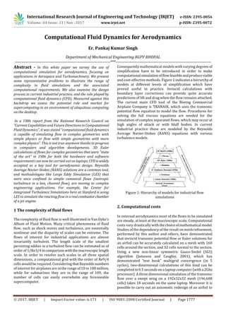
  • 1. International Research Journal of Engineering and Technology (IRJET) e-ISSN: 2395-0056 Volume: 04 Issue: 11 | Nov -2017 www.irjet.net p-ISSN: 2395-0072 © 2017, IRJET | Impact Factor value: 6.171 | ISO 9001:2008 Certified Journal | Page 1777 Computational Fluid Dynamics for Aerodynamics Er. Pankaj Kumar Singh Department of Mechanical Engineering RGPV BHOPAL ---------------------------------------------------------------------***--------------------------------------------------------------------- Abstract - In this white paper we survey the use of computational simulation for aerodynamics, focusing on applications in Aerospace and Turbomachinery. We present some representative problems to illustrate the range of complexity in fluid simulations and the associated computational requirements. We also examine the design process in current industrial practice, and the role played by computational fluid dynamics (CFD). Measured against this backdrop we assess the potential role and market for supercomputing in an environment of ubiquitous computing on the desktop. In a 1986 report from the National Research Council on “Current Capabilities and Future Directions in Computational Fluid Dynamics”, it was stated “computational fluid dynamics is capable of simulating flow in complex geometries with simple physics or flow with simple geometries with more complex physics”. This is not true anymore thanks to progress in computers and algorithm developments. 3D Euler calculations of flows for complex geometries that were “state of the art” in 1986 for both the hardware and software requirements can now be carried out on laptops. CFD iswidely accepted as a key tool for aerodynamic design. Reynolds Average Navier-Stokes (RANS) solutions are a common tool, and methodologies like Large Eddy Simulation (LES) that were once confined to simple canonical flows (isotropic turbulence in a box, channel flow), are moving to complex engineering applications. For example, the Center for Integrated Turbulence Simulations here at Stanford is using LES to simulate the reacting flow in arealcombustorchamber of a jet engine. 1 The complexity of fluid flows The complexity of fluid flow is well illustrated in Van Dyke’s Album of Fluid Motion. Many critical phenomena of fluid flow, such as shock waves and turbulence, are essentially nonlinear and the disparity of scales can be extreme. The flows of interest for industrial applications are almost invariantly turbulent. The length scale of the smallest persisting eddies in a turbulent flow can be estimated as of order of 1/Re3/4incomparisonwiththemacroscopiclength scale. In order to resolve such scales in all three spatial dimensions, a computational grid with the order of Re9/4 cells would be required. Considering thatReynoldsnumbers of interest for airplanes are in the range of 10 to 100 million, while for submarines they are in the range of 109, the number of cells can easily overwhelm any foreseeable supercomputer. Consequently mathematical models with varying degrees of simplification have to be introduced in order to make computational simulationof flowfeasibleandproduceviable and cost-effective methods. Figure 1 indicates a hierarchy of models at different levels of simplification which have proved useful in practice. Inviscid calculations with boundary layer corrections can provide quite accurate predictions of lift and drag when the flow remains attached. The current main CFD tool of the Boeing Commercial Airplane Company is TRANAIR, which uses the transonic potential flow equation to model the flow. Procedures for solving the full viscous equations are needed for the simulation of complex separated flows, which may occur at high angles of attack or with bluff bodies. In current industrial practice these are modeled by the Reynolds Average Navier-Stokes (RANS) equations with various turbulence models. Figure 1: Hierarchy of models for industrial flow simulations 2. Computational costs In external aerodynamics most of the flows to be simulated are steady, at least at the macroscopic scale. Computational costs vary drastically with thechoiceofmathematical model. Studies of the dependency of the result on mesh refinement, performed by this author and others, have demonstrated that inviscid transonic potential flow or Euler solutions for an airfoil can be accurately calculated on a mesh with 160 cells around the section, and 32 cells normal to the section. Using a new non-linear symmetric Gauss-Siedel (SGS) algorithm (Jameson and Caugley, 2001), which has demonstrated “text book” multigrid convergence (in 5 cycles), two-dimensional calculations of this kind can be completed in 0.5 seconds on a laptop computer (witha 2Ghz processor). A three dimensional simulation of the transonic flow over a swept wing on a 192x32x32 mesh (196,608 cells) takes 18 seconds on the same laptop. Moreover it is possible to carry out an automatic redesign of an airfoil to
  • 2. International Research Journal of Engineering and Technology (IRJET) e-ISSN: 2395-0056 Volume: 04 Issue: 11 | Nov -2017 www.irjet.net p-ISSN: 2395-0072 © 2017, IRJET | Impact Factor value: 6.171 | ISO 9001:2008 Certified Journal | Page 1778 minimize its shock drag in 6.25 seconds, and to redesign the wing of a Boeing 747 in 330 seconds. Viscous simulationsathighReynoldsnumbersrequirevastly greater resources. On the order of 32 mesh intervals are needed to resolve a turbulent boundary layer, in addition to 32 intervals between the boundary layer and the far field, leading to a total of 64 intervals. In order to prevent degradations inaccuracyandconvergencedueto excessively large aspect ratios (in excess of 1,000) in the surface mesh cells, the chordwise resolution mustalsobeincreasedto512 intervals. Translated to three dimensions, this implies the need for meshes with 5-10 million cells (for example, 512x64x256 = 8,388,608 cells) for an adequate simulation of the flow past an isolated wing. When simulations are performed on less fine meshes with, say, 500,000 to 1 million cells, it is very hard to avoid mesh dependency in the solutions as well as sensitivity to the turbulence model. Currently Boeing uses meshes with 15-60 million cells for viscous simulations of commercial aircraft with their high lift systems deployed. Using a multigrid algorithm, 2000 or more cycles are required to reach a steady state, and it takes 1-3 days toturn around the calculations on a 200 processor Beowulf cluster. A further progression to large eddy simulation of complex configurations would require even greater resources. Suppose that a conservative estimate of the size of eddies in a boundary layer that ought to be resolved is 1/5 of the boundary layer thickness. Assuming that 10 points are needed to resolve a single eddy, the mesh interval should then be 1/50 of the boundary layer thickness. Moreover, since the eddies are three-dimensional, the same mesh interval should be used in all three directions. Now, if the boundary layer thickness is of the order of 0.01 of the chord length, 5,000 intervals will be needed in the chordwise direction, and for a wing with an aspect ratio of 10, 50,000 intervals will be needed in the spanwise direction. Thus, of the order of 50 x 5,000 x 50,000 or 12.5 billion mesh points would be needed in the boundary layer. If the time dependent behavior of the eddies is to be fully resolved using time steps on the order of the time for a wave to pass through a mesh interval, and one allows for a total time equal to the time required for wavestotravel threetimes the length of the chord, of the order of 15,000 time steps would be needed. A more refined estimate which allows for the varying thickness of the boundary layer, recently made by Spalart suggests an even more severe requirement. Performance beyond the teraflop (1012 operations per second) will be needed to attemptcalculationsofthisnature, which also have an information content far beyond what is needed for engineering analysis and design. The main current use of DNS and LES is to try to gain an improved insight into the physics of turbulent flow, which may in turn lead to improved turbulence models. There are also important industrial applications where the flow is inherently unsteady, witha correspondingincreasein the computational complexity even when using the RANS equations. One example is the simulation of a helicopter rotor in forward flight for which it would be necessary both to calculate the dynamic and aerolastic blade motions, and to track their trailing vortices. Of the order of 100 millionmesh cells would be needed. Another example is the simulation of turbomachinery. A jet-engine compressor typicallycontains of the order of 1000 passages in about 30 interleaved rows of rotating and fixed blades. While a smaller number of stages are needed in the turbine, a complete simulation ought to treat film cooling via numerous small holes in each blade, and transitional flow. Using a fully implicit dual time stepping scheme with a second-order accurate backward difference formula (BDF), the calculation, which isstill ongoingusing512processorsof an ASCI machine, requires of the order of 3 million CPU hours. The prohibitive computational cost of simulations of this magnitude rules out their industrial use. High lift configuration. 22 million cells solution PW6000 turbine, unsteady simulation with 94
  • 3. International Research Journal of Engineering and Technology (IRJET) e-ISSN: 2395-0056 Volume: 04 Issue: 11 | Nov -2017 www.irjet.net p-ISSN: 2395-0072 © 2017, IRJET | Impact Factor value: 6.171 | ISO 9001:2008 Certified Journal | Page 1779 3. The role of CFD in the design process The actual use of CFD by Aerospace companies is a consequence of the trade-off betweenperceived benefits and costs. While the benefits are widely recognized, computational costs can not be allowed toswampthedesign process. The need for rapid turnaround, including the setup time, is also crucial. In current industrial practice, the design process can generally be divided into three phases: conceptual design, preliminary design, and final detaileddesign,asillustratedin Figure 2. The conceptual design stage, typically carried out by a staff of 15-30 engineers, defines the mission in the light of anticipated market requirements, and determines a general preliminary configuration, together with first estimates of size, weight and performance. The costs of this phase are in the range of 6-12 million dollars. In the preliminary design stage the aerodynamic shape and structural skeleton progress to the point where detailed performance estimates can be made and guaranteed to potential customers, who can then, in turn, formally sign binding contracts for the purchase of a certain number of aircraft. A staff of 100-300 engineers is generally employed for up to 2 years, at a cost of 60-120 million dollars. Initial aerodynamic performance is explored by computational simulations and through wind tunnel tests. While the costs are still fairly moderate, decisions made at this stage essentially determine both the final performance and the development costs. Figure 4: Phases of design In the final design stage the structure must be defined in complete detail, together with complete systems, including the flight deck, control systems (involving major software development for fly-by-wire systems), avionics, electrical and hydraulic systems, landing gear, weapon systems for military aircraft, and cabin layout for commercial aircraft. Major costs are incurred at this stage, during which it is also necessary to prepare a detailed manufacturing plan. Thousands of engineers define every part of the aircraft. Total costs are 3-10 billion dollars. Thus, the final design would normally be carried out only if sufficient orders have been received to indicate a reasonably high probability of recovering a significant fraction of the investment. In the development of commercial aircraft, aerodynamic design plays a leading role during the preliminary design stage, in the course of which the definition of the external aerodynamic shape is typically finalized. The aerodynamic lines of the Boeing 777 were frozen, for example, when initial orders were accepted, before the initiation of the detailed design of the structure. The starting point is an initial CAD definition resulting from the conceptual design. The inner loop of aerodynamic analysis is contained in an outer multi-disciplinary loop, which is in turn contained in a major design cycle involving wind tunnel testing. In recent Boeing practice, three major design cycles, each requiring about 4-6 months, have been used to finalize the wing design. Improvements in CFD, might allow the elimination of a major cycle, would significantly shorten the overall design process and reduce costs. Moreover, the improvements in the performance of thefinal design, which might be realized through the systematic use of CFD, could have a crucial impact. An improvement of 5 percent in lift to drag (L/D) ratio directly translates to a similar reduction in fuel consumption. With the annual fuel costs of a long-range airliner in the range of $5-10 million, a 5 percent saving would amount to a saving of the order of $10 million over a 25 year operational life, or $5 billion for a fleet of 500 aircraft. In fact an improvement in L/D enables a smaller aircraft to perform the same mission, so that the actual reduction in both initial and operating costs may be several times larger. Furthermore a small performance advantage can lead to a significant shift in the share of a market estimated to be more than $1 trillion over the next decades. In order to realize these advantages it is essential to move beyond flow simulation to a capability for aerodynamic shape optimization (a main focus of the firstauthorresearch during the past decade) and ultimately multidisciplinary system optimization. The result of an automatic redesign of the wing of the Boeing 747, which indicates the potential for a 5 percent reduction in the total drag of the aircraft by a very small shape modification. It is also important to recognize that in current practice the setup times and costs of CFD simulations substantially exceed the solution times and costs. With presently availablesoftwaretheprocesses of geometry modelling and grid generation may take weeks or even months. In the preliminary design of the F22 Lockheed relied largely on wind-tunnel testing because they could build models faster than they could generate meshes. It is essential to remove this bottleneck if CFD is to be more effectively used. There have been major efforts in Europe to develop an integrated software environment for aerodynamic simulations, exemplified by the German “Megaflow” program.
  • 4. International Research Journal of Engineering and Technology (IRJET) e-ISSN: 2395-0056 Volume: 04 Issue: 11 | Nov -2017 www.irjet.net p-ISSN: 2395-0072 © 2017, IRJET | Impact Factor value: 6.171 | ISO 9001:2008 Certified Journal | Page 1780 In the final-design stage it is necessary to predict the loads throughout the flight envelope. As many as 20000 design points may be considered. In current practice wind-tunnel testing is used to acquire the loads data, both because the cumulative cost of acquisition via CFD still exceeds the costs of building and testing properly instrumented models, and because a lack of confidence in the reliability of CFD simulations of extreme flight conditions. 4. CFD algorithms and software Commercial CFD software is widely available, and now amounts to an industry with annual revenues in therange of $200 million. The best known examples (CFX, Fluent and Star-CD) all had their origin in England. Commercial software, however, has yet to gain acceptance as a design tool in the Aerospace Industry, which continues to use community codes, many of them developed by government agencies such as NASA, ONERA and the DLR.Oncea code has been adopted, users are very reluctant to switch to a new code because of the large investment in familiarization and validation. Accordinglysoftwaretendstohavea muchlonger operational life than hardware. For example,FLO22,written by Jameson and Caughey in 1975, has continued to be extensively used to the present day. The driving force in the development of CFD through the eighties was the design of shock capturing schemes which could resolve shock waves in one or two mesh cells without producing spurious oscillations. Complete success was achieved with the introduction of TVD, LED, ENO andWENO schemes. The need to treat very complex geometric configurations also poses a severe challenge. Body fitted structured meshes provide good resolution of boundary layers, but it is extremely difficult and time consuming to generate these meshes for configurations like, for example, the Space Shuttle at launch. Thedifficultyofmeshgeneration may be alleviated by the use of overset meshes as in NASA’s OVERFLOW, but automatic generation of structuredmeshes remains out of reach. In the case of inviscidflowsimulations, one response is a trend towards the useofCartesian meshes, which are amenable to automatic generation (Boeing’s TRANAIR, Lockheed’s SPLITFLOW, NASA’s CART3D). The other approach which is beingincreasinglyacceptedisto use unstructured meshes with tetrahedral or mixed polyhedral cells. Examples includetheauthor’sAIRPLANEcode,introducedin 1986, but still in use at NASA Ames, EADS’ AIRPLANE+, a derivative of AIRPLANE, the DLR’sTAUcode,NASA’sUSM3D and FUN3D, and CFD++, offered by Meta comp. The use of unstructured meshes alleviates (but not entirelyeliminates) the difficulty of mesh generation and facilitates adaptive mesh refinement (AMR). It is harder to formulate accurate viscous discretizations, and also higher-accurate discretizationsbecomevery complicated.Thishasmotivated widespread current interest in discontinuous Galerkin schemes, which offer the prospect of higher order accurate discretization with a compact stencil. Time stepping methods have proven to offer an expedient route to the calculations of steady as well as unsteady flows. However, simple explicit schemes require many thousands of time steps to reach a steady state. This has motivated the introduction of a variety of alternative methods, including alternating direction implicit (ADI) schemes,LUimplicitand symmetric Gauss- Seidel (SGS) schemes, and acceleration techniques such as Jacobian free Newton-Krylov and multi grid procedures. The choice of an algorithm cannot be made without considering the computer architecture. There is nothing inherently preventingparallelisminflowsimulation algorithms, but parallelism may be lost in the formulation of implicit schemes. At the beginning of the eighties, with the expectation that future computing platforms would be parallel, the first author focused on the development of explicit schemes, using modified Runge-Kutta methodswith enlarged stability regions, embedded in a multi grid procedure. This approach, which is easily adaptable to arbitrary grids, and allows complete parallelization, continues to be widely used both in the USA and Europe. However, recent results of Jameson and Caughey clearly demonstrate that Gauss- Seidel methods can be about 5 times faster, and would be preferred for calculations on single processor machines. Ultimately it seems that the best performance could be attained by an algorithm thatuses the latest accessible data to update the solution at all times. In many unsteady flow of interest, the time scales that need to be resolved are much larger than the acoustic time scale. In this situation the authors believe that the most efficient approach is to use a fast steady-state solver to perform the inner iterations of a fully implicit scheme using a backward difference formula (BDF). In Stanford’s ASCI alliance centre simulations of the turbine and compressor, we use a “dual time stepping” scheme of this kind, which inherits the parallelism of the solver used in the inner iterations. In the case of a periodic unsteady flow we believe that there are advantages in using a time spectral method, in whichthe time derivative is discretized by a pseudo-spectral method. This leads to an integrated space-time formulation in which the discrete equations are simultaneously solved forall time levels by a multi grid procedure. 5. Aerodynamic performance prediction The state-of-the-art in CFD drag prediction was recently assessed by an international workshoponthesubject.Figure 5 provides the 28 drag polars resulting from this drag prediction workshop (DPW). With the exception of a few out-layers, the computed polars fall within a band of about 7% the absolute level.
  • 5. International Research Journal of Engineering and Technology (IRJET) e-ISSN: 2395-0056 Volume: 04 Issue: 11 | Nov -2017 www.irjet.net p-ISSN: 2395-0072 © 2017, IRJET | Impact Factor value: 6.171 | ISO 9001:2008 Certified Journal | Page 1781 Figure 5: Results from the Drag Prediction Workshop The slopes are nearly identical. When comparing the CFD results with the test data, we note that the CFD solutions were all run assuming fully turbulent flow, while the test data were collected with laminar runs on the wing up to transition strips on both upper and lower surfaces. To quantify the shift in drag associated with this difference, several independent calculations were performed yielding 12-13 counts higher drag levels for the fully turbulent flows. Accounting for this adjustment, the center of the CFD drag polars band coincides with the mean of the test polars. While this indicates that the industry as a whole is closing in on the ability to compute accurate absolute drag levels, in general, the errors are not to the level desired by aircraft design teams. However, a few of the results submitted to the DPW fall within the uncertainty band of the experimental data. Achieving this level of accuracy is dominated by the quality of the underlying grid, but also depends on the turbulence model, the level of convergence, discretization scheme, etc. It is imperative that each of these areas be studied independently of each other, otherwise "accurate" results might be obtained as a consequenceofcancellationof errors. Unfortunately, an optimization based on an analysis method containing such a cancellation of errors will most likely emphasize its weakness and probably yield a new design with a false performance improvement. 6. The current supercomputer scenario In the last decade, we have seen a departure from the “old” vector supercomputer model. Until the advent of the Earth Simulator (ES), the top supercomputers in the world were just “clusters on steroids”, a collectionofcommercial servers or workstations interconnected by high-speed network. While these super-clusters have theoretical peak performance in the Teraflops range, sustained performance with real applications is far from the peak. Salinas,oneofthe 2002 Gordon Bell Awards, was able to sustain 1.16Tflopson ASCI White (less than 10% of peak). Sustained performance in the single digit is the rule not the exception. The Earth Simulator and the Cray X1, two custom engineered systems with exceptional memory bandwidth, interconnect performance and vector-processing capabilities, are pushing theidea ofreal supercomputerback on the stage. A global atmospheric simulation was able to achieve 65% of the peak performance of theEarthSimulator and other CFD simulations were in the 30-50% range. The main limitation of the clusters built from commercial servers and workstation is the limited memory bandwidth that these platforms offer. In CFD, most of the algorithms do not reuse the data, and the benefit of cache (essentially a memory bandwidth amplifier) cannot be used.Thesituation is even more severe for codes using unstructured meshes, often a necessity in the treatment of very complex geometries. Indirect addressing (necessary to handle the complex data structures) just kills the performances. Vector machine were much more efficient on these codes, thanksto the vector load/store instructions that could address non contiguous memory locations. While in the old Cray days, it was the norm to sustain 50% of peak performance, now we are happy when we get 10%! Nevertheless the clusters have an important role in these days. They are an economic way of providing fast turn- around time, more memory and decent levels of performances. Commercial vendors are also starting to pay attention to the memory bandwidth. 7. Visions for the future In the year 2001 a Sony Vaio 505 laptop computer with of 4 pounds and a price of $3,000 offered the same performance and memory as the Convex of 1986, which weighted about 1000 pound and cost $600,000. If the same trends persist over the next 15 years, the computational power needed for RANS simulations of the flow over a wing will reside in a device the size of a wristwatch with a price around $15. While the requirements for data transfer and visualization may preclude wristwatch computing, we can anticipate a ubiquitous computing environment in whicheveryengineer has the computing power on his desktop needed for the major tasks of aerodynamic and multidisciplinary analysis and design. While companies may supplement this with clusters to supportcalculationsrequiringa largethroughput, such as aerodynamic tools, it is not realistic to imagine that they will spend $20-100 million to buy a supercomputer. Accordingly it seems that Government intervention may be needed to sustain a viable market for supercomputers, perhaps through purchases for Government Laboratories, following the current pattern. Viewed in this light, it seems moreover that the best chance of an economically sustainable strategy is to pursue a scalable architecture, in which the same hardware and software components are
  • 6. International Research Journal of Engineering and Technology (IRJET) e-ISSN: 2395-0056 Volume: 04 Issue: 11 | Nov -2017 www.irjet.net p-ISSN: 2395-0072 © 2017, IRJET | Impact Factor value: 6.171 | ISO 9001:2008 Certified Journal | Page 1782 shared by machines of all sizes, ranging from the desktop through departmental servers to the largest supercomputers. 7. CONCLUSIONS A major drawback of massively parallel vector supercomputers is the cost: machines like the ES or the Cray X1 use custom components at all levels. Other strategies are being pursued to achieve high performance at a lower cost, for example the Virtual Vector Architecture of Blue Planet and machines using the concept of "system-on-a-chip" like Blue Gene/L. During the last few years, the Computer SystemsLaboratory at Stanford University, has shown the potential of a streaming processor for signal and image processing with the Imagine chip. Using stream processors as building blocks, a new high performance architecture could be built. The goal of the Stanford Streaming Supercomputer (now called Merrimac) project,undertheleadershipofProfs.Dally and Hanrahan, is to achieve superior performance through the combination of stream processors, a high-performance interconnection network that efficiently provides good global bandwidth, and a new programming paradigm to exploit this new architecture. The final hardware should be able to scale from a 2 Tflops workstation to a 2 Pflops machine-room size computer with up to 16K processors. There is a close collaboration betweena teamofapplications developers and the hardware and language group to design the hardware and the language specifications. Two CFD applications have been ported to Merrimac using the streaming paradigm, StreamFLO, a multigrid finite volume Euler solver (coded by the authors),andStreamFEM a finite-element code (coded by Tim Barth at NASA Ames). The initial performance studies are encouraging. There is another way to view the progress of computer hardware. In parallel with the steady increase in the sustained performance attained by the fastest supercomputers over the past 15 years, the size and cost of a computer sufficient for the majority of engineering simulationshasbeensteadily decreasing. REFERENCES 1. M. Van Dyke, “An album of fluid motion”, Parabolic Press, 1982 2. A. Jameson, ”A perspective on computational algorithms for aerodynamic analysis and design”, Progress in Aerospace Sciences, 2001, vol. 37, pp 197-243. 3. A. Jameson and D.A. Caughey, ”How Many Steps are Required to Solve the Euler Equations of Steady Compressible Flow: In Search of a Fast Solution Algorithm” , AIAA 2001-2673, 15th AIAA Computational FluidDynamicsConference,June11- 14, 2001, Anaheim, CA. P. Moin and K. Kim, “Tackling turbulence with supercomputers”, Scientific American, January 1997,vol.276,No1,pp 62-68. 4. M. Fatica, A. Jameson and J.J. Alonso, ”STREAMFLO: an Euler solver for streaming architectures”, AIAA paper 2004-1090, to be presented at 42nd Aerospace Sciences Meeting and Exhibit Conference, Reno, January 2004. 5. Dr. Nilanajn Malik, Assistant Professor,Department of Mechanical Engineering Indian Institute of Technology BHU Varanasi. 6. Prof. A. K Agrawal, Head of Department, Department of Mechanical Engineering Indian Institute of Technology BHU Varanasi BIOGRAPHIES Er. Pankaj Kumar Singh Department Of Mechanical Engineering RGPV BHOPAL