This document summarizes a computational fluid dynamics (CFD) simulation of flow over an Ahmed body using Reynolds-averaged Navier-Stokes (RANS) turbulence modelling. Three grids with different refinements were used. The Realizable k-epsilon turbulence model was chosen. The simulation results showed improved prediction of drag coefficient with finer grids but poorer prediction of velocity profiles compared to experimental data. Flow analysis identified two main vortices in the wake, with higher turbulence kinetic energy around the lower vortex, consistent with experiments.
![Validation of CFD Simulation for Ahmed Body using RANS
Turbulence Modelling
Suyash Sharma
M.Sc. Computational Fluid Dynamics
School of Aerospace, Transport & Management, Cranfield University, Cranfield MK43 0AL, UK
Submitted 31ST
March 2016
Abstract
The flow modelling of Ahmed Body is a benchmark for the ground vehicle external aerodynamics for the drag generated
at the vehicle rear. Studies have been carried out in the past decades for the flow around a simplified vehicle model at various
rear slant angles to model the relation between the geometry and drag. The current CFD study models the flow using a RANS
turbulence models also carrying out the grid sensitivity analysis.
The study had been carried out on three different refinement levels of the grid constituting tetra-prism meshing. Two
equation turbulence model was chosen for the turbulence modelling and the results have been below satisfactory in terms of
velocity flow field compared with the experimental data.
Keywords: Ahmed Body, RANS, Vortices
1. Introduction
Aerodynamic performance of the ground vehicle is
vital criterion in today’s world even more so when
facing a global energy crisis. Saving fuel by
improving external aerodynamics is in hot pursuit of
the researchers globally. Quite a number of leading
researchers have been routinely performing tests on
assessing and improving this parameter. With the
development of computing power and numerical
methods, the exercise is no longer limited to the
expensive wind tunnel tests but can be carried out to
a convincing level of accuracy through turbulence
modelling like LES and DES. Currently, Reynolds
averaged turbulence models have been adopted
frequently in the development of road vehicle due to
its cost effectiveness and as a guidance for the wind
tunnel hot zones.
The benchmark experiment for the problem was
performed by [1] on a wooden model with a
simplified ground vehicle geometry. Further to this
experiment was a wind tunnel test performed by [2]
in 2000 using an LDA and PIV for validating the
results. A number of other researches numerical or
computational [3] were performed around the same
period to investigate the flow or to validate the
turbulence models as well as modified turbulent
stress calculations. A more accurate attempt at
resolving the flow features around ahmed body can
be found in [4] [5] [6] [7] [8].
The main objective of the experiments is to be able
to define the behaviour of the flow and to relocate
the separation point to alter the pressure gradient in
the rear. The aim of the current study is to validate
the results of CFD simulation of the Ahmed Body
using RANS turbulence modelling approach against
the results from the experiment performed by
Ahmed and Lienhart.
1.1 Problem Physics
The problem involves a bluff body kept in a wind
tunnel with a steady flow and with a turbulence
intensity of less than 0.25% and a viscosity ratio of
10. The flow over the surface is only slightly (micro)
separated at the rear slant of the Ahmed body with a
very thin recirculation region. The type of
turbulence that occurs for attached boundaries layers
is confined to a very thin layer near the vehicle
surface. The skin friction is an outcome of the drag
produced in this surface whereas immediately above
this surface the flow in unimpeded at the top and
bottom edges of the rear vertical plane of the ahmed
body the shear layer rolls up and constitutes 2 major
(B & C) and a minor vortex (A) structure.
Figure 1 Vortex Structures](https://image.slidesharecdn.com/c61f7a02-2cee-42f6-be5b-a40924ba62cc-161103233613/85/ASSIGNMENT-1-320.jpg)
![Validation of CFD Simulation for Ahmed Body using RANS
Turbulence Modelling
Suyash Sharma
M.Sc. Computational Fluid Dynamics
School of Aerospace, Transport & Management, Cranfield University, Cranfield MK43 0AL, UK
Submitted 31ST
March 2016
Abstract
The flow modelling of Ahmed Body is a benchmark for the ground vehicle external aerodynamics for the drag generated
at the vehicle rear. Studies have been carried out in the past decades for the flow around a simplified vehicle model at various
rear slant angles to model the relation between the geometry and drag. The current CFD study models the flow using a RANS
turbulence models also carrying out the grid sensitivity analysis.
The study had been carried out on three different refinement levels of the grid constituting tetra-prism meshing. Two
equation turbulence model was chosen for the turbulence modelling and the results have been below satisfactory in terms of
velocity flow field compared with the experimental data.
Keywords: Ahmed Body, RANS, Vortices
1. Introduction
Aerodynamic performance of the ground vehicle is
vital criterion in today’s world even more so when
facing a global energy crisis. Saving fuel by
improving external aerodynamics is in hot pursuit of
the researchers globally. Quite a number of leading
researchers have been routinely performing tests on
assessing and improving this parameter. With the
development of computing power and numerical
methods, the exercise is no longer limited to the
expensive wind tunnel tests but can be carried out to
a convincing level of accuracy through turbulence
modelling like LES and DES. Currently, Reynolds
averaged turbulence models have been adopted
frequently in the development of road vehicle due to
its cost effectiveness and as a guidance for the wind
tunnel hot zones.
The benchmark experiment for the problem was
performed by [1] on a wooden model with a
simplified ground vehicle geometry. Further to this
experiment was a wind tunnel test performed by [2]
in 2000 using an LDA and PIV for validating the
results. A number of other researches numerical or
computational [3] were performed around the same
period to investigate the flow or to validate the
turbulence models as well as modified turbulent
stress calculations. A more accurate attempt at
resolving the flow features around ahmed body can
be found in [4] [5] [6] [7] [8].
The main objective of the experiments is to be able
to define the behaviour of the flow and to relocate
the separation point to alter the pressure gradient in
the rear. The aim of the current study is to validate
the results of CFD simulation of the Ahmed Body
using RANS turbulence modelling approach against
the results from the experiment performed by
Ahmed and Lienhart.
1.1 Problem Physics
The problem involves a bluff body kept in a wind
tunnel with a steady flow and with a turbulence
intensity of less than 0.25% and a viscosity ratio of
10. The flow over the surface is only slightly (micro)
separated at the rear slant of the Ahmed body with a
very thin recirculation region. The type of
turbulence that occurs for attached boundaries layers
is confined to a very thin layer near the vehicle
surface. The skin friction is an outcome of the drag
produced in this surface whereas immediately above
this surface the flow in unimpeded at the top and
bottom edges of the rear vertical plane of the ahmed
body the shear layer rolls up and constitutes 2 major
(B & C) and a minor vortex (A) structure.
Figure 1 Vortex Structures](https://image.slidesharecdn.com/c61f7a02-2cee-42f6-be5b-a40924ba62cc-161103233613/75/ASSIGNMENT-1-2048.jpg)
![The C pillar vortices are so named due to their
formation at the 3rd
or C pillar of the vehicle
structure supporting the roof. They are conical in
shape and produce a downwash between them. [9]
2. Solution Procedure
2.1 Computational Domain
The domain size for the virtual wind tunnel was
chosen based on the experiment in wind tunnel cross
section and the standard blockage ratio defined by
the ERCOFTAC for Ahmed Body experiments.
[5][3] [10] .
Tunnel Length 𝐿 𝑊𝑇,𝐴 8.192[m]
Clearance Inlet , Ahmed Body 𝐼 𝑊𝑇,𝐴 2.048[m]
Clearance Ahmed Body, Outlet 𝑂 𝑊𝑇,𝐴 5.12[m]
Width 𝑊 𝑊𝑇,𝐴 1.43[m]
Height 𝐻 𝑊𝑇,𝐴 1.91[m]
Cross Section 𝐴 𝑊𝑇,𝐴 2.73[m2]
Blockage Ratio ∁ 𝑊𝑇,𝐴 4.2 %
Table 1 Virtual Wind Tunnel Dim.
Note: Fore area of Ahmed Body is 0.115 m2
The supporting stilts used by Ahmed have been
included in the geometry and is also kept at 0.05m
above the floor surface.
Figure 2 Computational Domain
2.2 Mesh Generation
Mesh was generated using Ansys ICEM since it
allows for certain controls over the hex cells that
are not available in Ansys workbench.
For the construction of the computational grids, the
same criterion has been followed for both the
geometrical configurations and for the different
near-wall treatments:
although the geometry is simplified, the sections on
the ahmed body with curvature and shard edges are
difficult to mesh using a structured C-type grid
approach thus all the grids are composed of a prism
layered structure near the walls as in Figure X, with
the remaining part of the domain filled with
tetrahedrons. In addition, local refinements have
been introduced around the body surface and in the
rear wake region. Due to the symmetrical shape of
the body, in the steady-state runs only half of the
domain has been modeled. [11]
Figure 3 Prism w/t tetra at the stilt T junction
The main aim in the meshing method was to avoid
the generation of pyramids that result to poor
convergence and solution in CFD simulation. The
domain was filled with tetra mesh in the start with a
max element size of 150mm and an Octree volume
mesh was generated. The max cell size for ahmed
body was taken to be 10mm for coarse, 5mm for
medium and 1.75 for fine mesh based on y+ and
flow velocity [12]. The octree tetra has sharp
transitions and utilizes almost 50% higher number of
nodes as compared with the bottom up tetra
methods. By using Delaunay, cell count was reduced
along with a better mesh transition. To improve the
mesh transition, the octree volume mesh was deleted
leaving the surface triangles which were
smoothened using Laplace smoothing. Since the
smoothing of prism at the very end would be very
difficult for the meshing algorithm, the quality of
mesh had to be protected from the beginning. The
volume mesh was then regenerated using Quick
Delaunay method with Advancing Front and TGlib
since it can be more difficult to perform if the prism
layers are already present. The boundary layer was
then filled with Prism layers the height of which was
kept floating to allow for an automatic adjustment of
the last cell size in prism to match the adjacent tetra.](https://image.slidesharecdn.com/c61f7a02-2cee-42f6-be5b-a40924ba62cc-161103233613/85/ASSIGNMENT-2-320.jpg)
![A smoothing operation was later performed by
freezing the components of the of the grid
sequentially so as to match the corresponding
smoothing operation. For ex. Laplace smoothing is
performed only on the Tri’s keeping the tetras
frozen. [13] [14] [15]
2.3 Solver Parameters
Ansys Fluent 16 was utilized as the solver for
solving the flow equations. A pressure based steady
flow was assumed for the simplicity of the process
compared to a transient flow averaged over time for
the different parameters. Similarly, a pressure based
coupled solver was used, which solves the
momentum and pressure based continuity equations
in a coupled manner thus reducing the overall
convergence up to five times that in Simple or
Simplec. Though the memory requirements are
larger but the gains outweigh the resource
requirements. Thus the PB CS is gaining popularity
for subsonic external flows. [16]
2.3.1 Turbulence Model & Governing Eq.
The net effect of the wall through the applied skin
friction has to be captured by the turbulence model
to form the attached boundary layers, instead of
basing the calculation on the velocity profile that
goes to zero near the wall.
The applied k-𝝐 Realizable model is the most stable
from the optional types because it uses mathematical
constrains on the Reynolds stresses and transport
equations and uses wall functions for near wall
treatment. Governing equations of the model are
solving the equation for kinetic energy k and the
turbulent dissipation rate 𝜖. These contain the
variation of the variables with different constants
and terms (1), (2). The model’s turbulent viscosity
equation can be found in the eq. (3).
𝜕
𝜕𝑡
(𝜌𝑘) +
𝜕
𝜕𝑥𝑖
(𝜌𝑘𝑢𝑖) =
𝜕
𝜕𝑥𝑗
[(𝜇 +
𝜇 𝑡
𝜎𝑘
)
𝜕𝑘
𝜕𝑥𝑗
]
+ 𝐺 𝑘 + 𝐺 𝑏 + 𝜌𝜀 − 𝑌 𝑚
+ 𝑆 𝑘
(1)
𝜕
𝜕𝑡
(𝜌𝜀) +
𝜕
𝜕𝑥𝑖
(𝜌𝜀𝑢𝑖) =
𝜕
𝜕𝑥𝑗
[(𝜇 +
𝜇 𝑡
𝜎𝜀
)
𝜕𝜀
𝜕𝑥𝑗
]
+ 𝜌𝐶1 𝑆𝜀 + 𝜌𝐶2
𝜀2
𝑘 + √ 𝛾𝜀
+ 𝐶1𝜀
𝜀
𝑘
𝐶3𝜀 𝐺 𝑏 + 𝑆𝜀
(2)
𝜇 𝑡 = 𝜌𝐶𝜇
𝐾2
𝜀 (3)
Through the following, the 𝐾 − 𝜖 − 𝑅𝑒𝑎𝑙𝑖𝑧𝑎𝑏𝑙𝑒
intended to address the common deficiencies of the
similar 𝐾 − 𝜖 models :
A new eddy-viscosity formula involving a
variable for 𝐶𝜇 originally proposed by
Reynolds [17]
A new model equation for dissipation
based on the dynamic equation of the mean
square vorticity fluctuation [17]
For integral values such as drag and lift, the model
shows a low error value in the order of 2-5%. The
turbulence model is very stable and fast converging
and is time saving in industrial applications.
Except for the standard k - ε model most of the other
models showed no discrepancies with the
experimental drag values. Considering the drag
coefficient and lift coefficients comprehensively,
Realizable k - ε model and LES models give superior
results than other drag models but LES is resource
consuming and since we had to choose one of the
RANS models for the study, Realizable K-Epsilon
was chosen for the task. Wall functions were also
used because of the high Reynolds number which
does not allow a fine resolution of the near wall flow
down to the viscous sub-layer. Fluent offered the
option of Non-Equilibrium Wall Functions (NWFs).
These wall functions are sensitized to pressure
gradient effects and this feature is of huge
importance in ground vehicle aerodynamics.
3.3.2 Initial & Boundary Conditions
According to [10] [18], a no-slip wall boundary
condition has been appointed only to the floor and
the surface of the ahmed body while leaving the
wind tunnel surfaces as free-slip boundary. At the
inlet a velocity of 40m/s has been appointed and the
corresponding Reynold’s number of 2.78 x 10⁶
has
been calculated based on fluid flow velocity and the
boundary layer characteristic length in the
streamwise direction. At the outlet a zero pressure
gradient has been used. The experimental values of
the initial conditions such as turbulent intensity and
viscosity ratio defined already in this study were
chosen. (0.25 % and 10 respectively).
3.3.3 Solution Controls & Initialization
The under relaxation values were taken as default for
the solver except the value for the turbulent viscosity
relaxation was taken as 0.80 for the 1st
round of
initialization with hybrid+100 iterations on 1st
order
upwind, and then increased to 0.95 for the second
order discretization further from that point.](https://image.slidesharecdn.com/c61f7a02-2cee-42f6-be5b-a40924ba62cc-161103233613/85/ASSIGNMENT-3-320.jpg)
![3. Results & Analysis
Results from the CFD simulation have been
presented in this section. The simulations show 3D
flow features around the Ahmed body in partial
agreement with the experiment done by (Lienhart et
al. 2000).
3.1 Grid Sensitivity
The grid refinement produced a surge in the
accuracy of the drag prediction. The grid refinement
owing to the y+ value captured the viscous sub-layer
relatively better than the previous grids and also
gained in predicting the value of the skin-friction
drag which is although negligible in this case.
Cells 𝑪 𝑫 Δ 𝑪 𝑫%
Wind Tunnel Exp - 0.287
Coarse Mesh (K-ep-Rlz) 1.15M 0.303 5.5%
Medium Mesh(K-ep-Rlz) 5.20M 0.296 3.13%
Fine Mesh (K-ep-Rlz) 13.0M 0.289 0.69%
Table 2 Drag Coefficient & Error
**The drag coefficient is defined as 𝐶 𝐷 =
2 𝐹 𝐷
𝜌 𝑈∞
2 𝐴 𝑥
where 𝐴 𝑥 is the projected area of the car in
streamwise direction and 𝐹𝐷 the drag force.
Although the CPU time for computation increased
significantly with the fine mesh, the increment in the
accuracy was also proportional.
3.2 A Posteriori (Actual Y+)
The actual local y+ as can be seen in the Figure 4
reflects the change in the reference velocity over the
external surface of the ahmed body. The areas in red
are subject to higher than the reference flow velocity
while some areas experience a receded flow. The Y+
varies between 1 – 60. This suggests the use of
different y+ values on the different part of the body
depending on the local wall shear stresses.
Figure 4 Wall Y+
Number of Nodes. 1st
Cell Height 𝒚+
min 𝒚+
max
325172 2.8[mm] 21 198
1885712 1.4[mm] 14 129
4271428 0.47[mm] 4 54
Table 3 Y+ Variation
3.3 Turbulent Velocity Profiles
Figure 5 Turbulent U-Velocity Profiles
Figure 5 gives a velocity profile comparison of the
CFD results with the experiment. Geometric scales
were non-dimensionalized by the ahmed body
height (0.288mm). The velocity profile predicted by
the K-ep model do not fit well with the experimental
data. As the industrial experience shows that the
turbulence model is good in predicting the integral
values such as drag coefficient, the difference in
velocity gradient at the slant and the rear end of the
ahmed body was somewhat expected.
The model did not rigorously account for the
anisotropy of the turbulence and the transport of all
turbulence stresses which could have been achieved
through the use of RSM model which follows
turbulence stress terms in all the directions. RSM
had been suggested in the referred literature [12] but
it takes almost 50% more computational resources
than K-ep thus for the fine mesh, we stick with K-
ep.](https://image.slidesharecdn.com/c61f7a02-2cee-42f6-be5b-a40924ba62cc-161103233613/85/ASSIGNMENT-4-320.jpg)
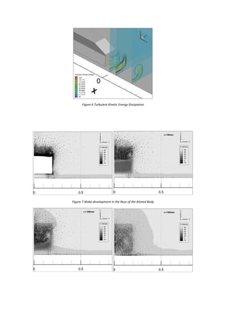
![3.4 Flow Analysis
At 40m/s air speed an unsteady wake at the rear is
generated with two significant vortex structures. The
higher of the two vortices is also bigger in size as
can be seen in figure 4. The two vortices were called
A & B vortices in [10].The background colour and
position of the turbulent kinetic energy
concentration Figure 6, shows a higher value around
the lower vortex as observed in the experiment [10].
Also because of the choice of the turbulence model,
the separation region over the slant of the ahmed
body is entirely non-existent which is otherwise
prominent in other turbulence model approaches.
The development of wake can be observed in the
Figure 7 where the vortical flow has been mapped
on the wake of the ahmed body.
Figure 8 shows the velocity and flow field in the
symmetry plane of the Ahmed body. Vortical
structures do not extend more than 0.5m behind the
rear vertical plane. Also the reverse flow spans the
full height of the vertical plane, as observed in the
experiment [10].
Figure 8 Velocity Contours in Symmetry Plane
Figure X shows the comparison of the turbulent
kinetic energy dissipation in the wake of the flow
past the Ahmed body. The results were plotted in
correspondence with the experiment [2]. Another
critical flow characteristic is the C-Pillar vortex
which had been modelled using the iso-surface for
the 2nd
Eigen value (Q-criterion). The vortex
structure had been captured well with the CFD
modelling approach as can be seen in Figure 9.
Figure 9 Iso-Surface for the Vortex Flow
4. Conclusion
The RANS turbulence model provides a good
starting point for the integral values such as drag and
lift but fails to map correctly the turbulent stresses in
all directions. The turbulent kinetic energy
dissipation and the drag coefficients have been
captured to a very satisfactory level but the micro
recirculation near the slant wall & the velocity
profiles have not been. The RSM turbulent model as
suggested in the [12] would have been a better
solution for an overall accurate result.](https://image.slidesharecdn.com/c61f7a02-2cee-42f6-be5b-a40924ba62cc-161103233613/85/ASSIGNMENT-6-320.jpg)
![5. References
[1] S. Ahmed, G. Ramm, and G. Faltin, “Some
salient features of the time-averaged ground
vehicle wake,” Changes, p. 34, 1984.
[2] H. LIENHART and S. BECKER, “Flow and
turbulence structure in the wake of a
simplified car model,” SAE Trans., vol. 112,
no. 6, pp. 785–796.
[3] E. Serre, M. Minguez, R. Pasquetti, E.
Guilmineau, G. B. Deng, M. Kornhaas, M.
Schäfer, J. Fröhlich, C. Hinterberger, and
W. Rodi, “On simulating the turbulent flow
around the Ahmed body: A French-German
collaborative evaluation of LES and DES,”
Comput. Fluids, vol. 78, pp. 10–23, 2013.
[4] I. Bayraktar and T. Bayraktar, “Assessment
of Reynolds Averaged Turbulence Models
in Predicting Flow Structure Behind a
Generic Automobile Body,” SAE Pap., vol.
2006, no. 724, pp. 2006–01–0139, 2006.
[5] C. Hinterberger, M. Garcia-Villalba, and W.
Rodi, “Large eddy simulation of flow
around the Ahmed body,” Aerodyn. Heavy
Veh. Truck. Buses, Trains, Vol. 1, 2004.
[6] Y. Liu and A. Moser, “Numerical modeling
of airflow over the Ahmed body,”
Proceeding 11th Annu. Conf. CFD Soc.
Canada, pp. 508–513, 2003.
[7] I. Bayraktar, D. Landman, and O. Baysal,
“Experimental and Computational
Investigation of Ahmed Body for Ground
Vehicle Aerodynamics,” SAE Tech. Pap.
Ser., no. 724, 2001.
[8] E. Guilmineau, “Numerical Simulation with
a DES Approach,” SAE Int. J. Passanger
Cars - Mech. Syst., vol. 3, no. 1, pp. 574–
587, 2014.
[9] M. Corallo, J. Sheridan, and M. C.
Thompson, “Effect of aspect ratio on the
near-wake flow structure of an Ahmed
body,” J. Wind Eng. Ind. Aerodyn., vol. 147,
no. 6, pp. 95–103, 2015.
[10] H. Lienhart, C. Stoots, and S. Becker, “Flow
and Turbulence Structures in the Wake of a
Simplified Car Model (Ahmed Model),”
SAE World Congr., no. Figure 3, pp. 323–
330, 2003.
[11] V. K. Krastev and G. Bella, “On the Steady
and Unsteady Turbulence Modeling in
Ground Vehicle Aerodynamic Design and
Optimization,” SAE Tech. Pap., 2011.
[12] F. D. Gmbh, “Best practice guidelines for
handling Automotive External
Aerodynamics with FLUENT,” vol. 2, pp.
1–14, 2005.
[13] T. D. Canonsburg and A. I. Cfd, “ANSYS
ICEM CFD User Manual,” Knowl. Creat.
Diffus. Util., vol. 15317, no. October, pp.
724–746, 2012.
[14] D. Ryan and C. Engineering, “ANSYS
ICEM CFD and ANSYS CFX Introductory
Training Course,” Training, pp. 1–20, 2011.
[15] S. Pereira, “ICEM CFD Tetra / Prism For
CFD ++ or Fluent Large model Strategy • If
your models are large and generating the
mesh takes,” pp. 1–21, 2007.
[16] P. C. Solver and P. Method, “Accelerating
CFD Solutions,” pp. 48–49, 2011.
[17] T.-H. Shih, W. W. Liou, A. Shabbir, Z.
Yang, and J. Zhu, “A new k-ϵ eddy viscosity
model for high reynolds number turbulent
flows,” Comput. Fluids, vol. 24, no. 3, pp.
227–238, 1995.
[18] R. Manceau and J.-P. Bonnett, “Report on
the 10th joint ERCOFTAC ( SIG-15 )/
IAHR / QNET-CFD Workshop on Refined
Turbulence Modelling,” in Report on the
10th joint ERCOFTAC ( SIG-15 )/ IAHR /
QNET-CFD Workshop on Refined
Turbulence Modelling, 2002.](https://image.slidesharecdn.com/c61f7a02-2cee-42f6-be5b-a40924ba62cc-161103233613/85/ASSIGNMENT-7-320.jpg)


