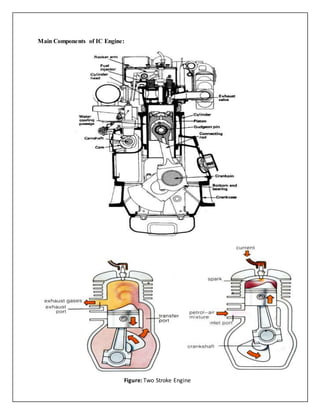
The document provides an overview of internal combustion engines (IC engines), detailing their definition, working principles, and main components such as cylinders, pistons, and crankshafts. It explains the four-stroke cycle, highlighting the sequence of strokes and the role of various elements in the combustion process. Additionally, it distinguishes between machines and engines while discussing applications and objectives related to IC engines.