Download to read offline
![1
COMPUTER ORGANIZATION
[As per Choice Based Credit System (CBCS) scheme]
(Effective from the academic year 2017 -2018)
SEMESTER - III
Subject Code 17CS34 IA Marks
40 Number of Lecture Hours/Week 04 Exam Marks 60
Total Number of Lecture Hours 50 Exam Hours 03
CREDITS – 04
Module -1 Teaching Hours
Basic Structure of Computers: Basic Operational Concepts, Bus Structures, Performance – Processor
Clock, Basic Performance Equation, Clock Rate, Performance Measurement. Machine Instructions
and Programs: Memory Location and Addresses,Memory Operations, Instructions and Instruction
Sequencing, Addressing Modes, Assembly Language, Basic Input and Output Operations, Stacks and
Queues,Subroutines, Additional Instructions, Encoding of Machine Instructions
10Hours
Module -2
Input/output Organization: Accessing I/O Devices,Interrupts – Interrupt Hardware,Enabling and
Disabling Interrupts, Handling Multiple Devices,Controlling Device Requests,Exceptions, Direct
Memory Access,Buses Interface Circuits,Standard I/O Interfaces – PCI Bus,SCSI Bus, USB.
10 Hours
Module – 3
Memory System: Basic Concepts, Semiconductor RAM Memories, Read Only Memories, Speed,
Size, and Cost, Cache Memories – Mapping Functions, Replacement Algorithms, Performance
Considerations, Virtual Memories, Secondary Storage. 10 Hours
Module-4
Arithmetic: Numbers, Arithmetic Operations and Characters,Addition and Subtraction of Signed
Numbers, Design of Fast Adders, Multiplication of Positive Numbers, Signed Operand
Multiplication, Fast Multiplication, Integer Division, Floating-point Numbers and Operations.
10 Hours
Module-5
Basic Processing Unit: Some Fundamental Concepts, Execution of a Complete Instruction, Multiple
Bus Organization, Hard-wired Control, Micro programmed Control. Pipelining, Embedded Systems
and Large Computer Systems: Basic Concepts of pipelining, Examples of Embedded Systems,
Processor chips for embedded applications, Simple Microcontroller, The structure of General-
Purpose Multiprocessors.
10 Hours](https://image.slidesharecdn.com/conotes3sem-180929072206/85/Co-notes3-sem-1-320.jpg)
![1
COMPUTER ORGANIZATION
[As per Choice Based Credit System (CBCS) scheme]
(Effective from the academic year 2017 -2018)
SEMESTER - III
Subject Code 17CS34 IA Marks
40 Number of Lecture Hours/Week 04 Exam Marks 60
Total Number of Lecture Hours 50 Exam Hours 03
CREDITS – 04
Module -1 Teaching Hours
Basic Structure of Computers: Basic Operational Concepts, Bus Structures, Performance – Processor
Clock, Basic Performance Equation, Clock Rate, Performance Measurement. Machine Instructions
and Programs: Memory Location and Addresses,Memory Operations, Instructions and Instruction
Sequencing, Addressing Modes, Assembly Language, Basic Input and Output Operations, Stacks and
Queues,Subroutines, Additional Instructions, Encoding of Machine Instructions
10Hours
Module -2
Input/output Organization: Accessing I/O Devices,Interrupts – Interrupt Hardware,Enabling and
Disabling Interrupts, Handling Multiple Devices,Controlling Device Requests,Exceptions, Direct
Memory Access,Buses Interface Circuits,Standard I/O Interfaces – PCI Bus,SCSI Bus, USB.
10 Hours
Module – 3
Memory System: Basic Concepts, Semiconductor RAM Memories, Read Only Memories, Speed,
Size, and Cost, Cache Memories – Mapping Functions, Replacement Algorithms, Performance
Considerations, Virtual Memories, Secondary Storage. 10 Hours
Module-4
Arithmetic: Numbers, Arithmetic Operations and Characters,Addition and Subtraction of Signed
Numbers, Design of Fast Adders, Multiplication of Positive Numbers, Signed Operand
Multiplication, Fast Multiplication, Integer Division, Floating-point Numbers and Operations.
10 Hours
Module-5
Basic Processing Unit: Some Fundamental Concepts, Execution of a Complete Instruction, Multiple
Bus Organization, Hard-wired Control, Micro programmed Control. Pipelining, Embedded Systems
and Large Computer Systems: Basic Concepts of pipelining, Examples of Embedded Systems,
Processor chips for embedded applications, Simple Microcontroller, The structure of General-
Purpose Multiprocessors.
10 Hours](https://image.slidesharecdn.com/conotes3sem-180929072206/75/Co-notes3-sem-1-2048.jpg)
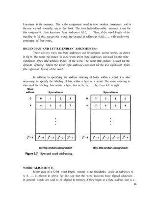
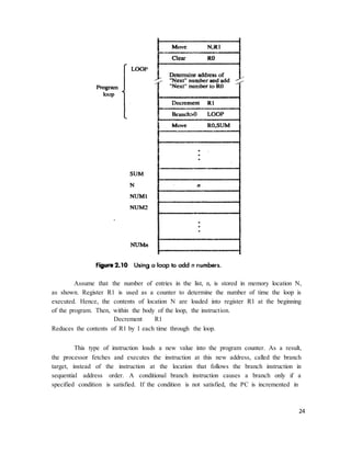
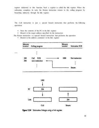
![18
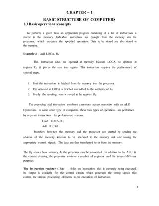
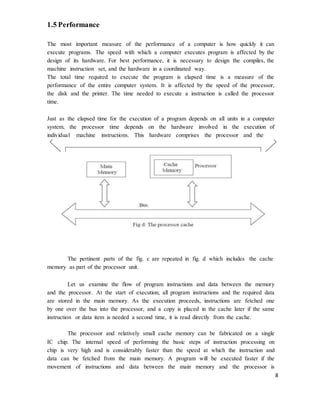
An information item of either one word or one byte can be transferred between
the processor and the memory in a single operation. Actually this transfer in between the
CPU register & main memory.
2.4 Instructions and instruction sequencing
A computer must have instructions capable of performing four types of
operations.
• Data transfers between the memory and the processor registers
• Arithmetic and logic operations on data
• Program sequencing and control
• I/O transfers
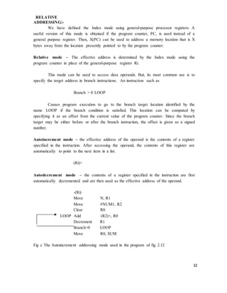
REGISTER TRANSFER NOTATION:-
Transfer of information from one location in the computer to another. Possible
locations that may be involved in such transfers are memory locations that may be
involved in such transfers are memory locations, processor registers, or registers in the
I/O subsystem. Most of the time, we identify a location by a symbolic name standing for
its hardware binary address.
Example, names for the addresses of memory locations may be LOC, PLACE, A,
VAR2; processor registers names may be R0, R5; and I/O register names may be
DATAIN, OUTSTATUS, and so on. The contents of a location are denoted by placing
square brackets around the name of the location. Thus, the expression
R1 �
[LOC]
Means that the contents of memory location LOC are transferred into processor register
R1.
As another example, consider the operation that adds the contents of registers R1
and R2, and then places their sum into register R3. This action is indicated as
R3 �
[R1] + [R2]
This type of notation is known as Register Transfer Notation (RTN). Note that
the right-hand side of an RTN expression always denotes a value, and the left-hand side
is the name of a location where the value is to be places, overwriting the old contents of
that location.
ASSEMBLY LANGUAGE NOTATION:-
Another type of notation to represent machine instructions and programs. For
this, we use an assembly language format. For example, an instruction that causes the](https://image.slidesharecdn.com/conotes3sem-180929072206/85/Co-notes3-sem-18-320.jpg)
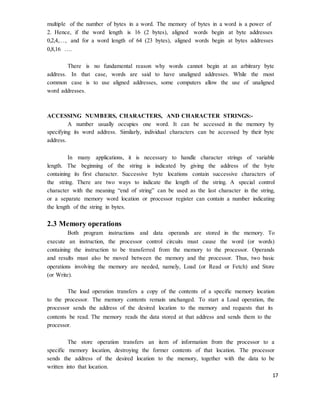
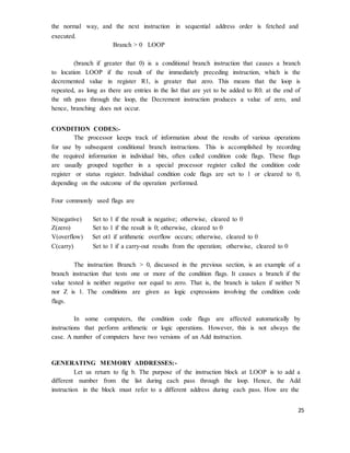
![19
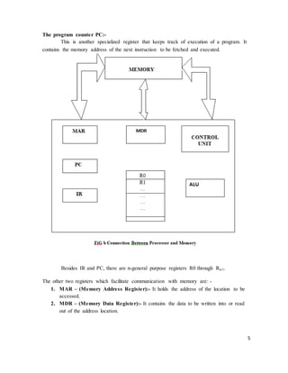
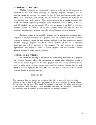
transfer described above, from memory location LOC to processor register R1, is
specified by the statement
Move LOC, R1
The contents of LOC are unchanged by the execution of this instruction, but the
old contents of register R1 are overwritten.
The second example of adding two numbers contained in processor registers R1
and R2 and placing their sum in R3 can be specified by the assembly language statement
Add R1, R2, R3
BASIC INSTRUCTIONS:-
The operation of adding two numbers is a fundamental capability in any
computer. The statement
C = A + B
In a high-level language program is a command to the computer to add the
current values of the two variables called A and B, and to assign the sum to a third
variable, C. When the program containing this statement is compiled, the three variables,
A, B, and C, are assigned to distinct locations in the memory. We will use the variable
names to refer to the corresponding memory location addresses. The contents of these
locations represent the values of the three variables. Hence, the above high-level
language statement requires the action.
C �
[A] + [B]
To carry out this action, the contents of memory locations A and B are fetched
from the memory and transferred into the processor where their sum is computed. This
result is then sent back to the memory and stored in location C.
Let us first assume that this action is to be accomplished by a single machine
instruction. Furthermore, assume that this instruction contains the memory addresses of
the three operands – A, B, and C. This three-address instruction can be represented
symbolically as
Add A, B, C
Operands A and B are called the source operands, C is called the destination
operand, and Add is the operation to be performed on the operands. A general instruction
of this type has the format.
Operation Source1, Source 2, Destination
If k bits are needed for specify the memory address of each operand, the encoded
form of the above instruction must contain 3k bits for addressing purposes in addition to](https://image.slidesharecdn.com/conotes3sem-180929072206/85/Co-notes3-sem-19-320.jpg)
![20
the bits needed to denote the Add operation.
An alternative approach is to use a sequence of simpler instructions to perform
the same task, with each instruction having only one or two operands. Suppose that two-
address instructions of the form
Operation Source, Destination
Are available. An Add instruction of this type is
Add A, B
Which performs the operation B �
[A] + [B].
A single two-address instruction cannot be used to solve our original problem,
which is to add the contents of locations A and B, without destroying either of them, and
to place the sum in location C. The problem can be solved by using another two-address
instruction that copies the contents of one memory location into another. Such an
instruction is
Move B, C
Which performs the operations C �
[B], leaving the contents of location B unchanged.
Using only one-address instructions, the operation C �
[A] + [B] can be
performed by executing the sequence of instructions
Load A
Add B
Store C
Some early computers were designed around a single accumulator structure.
Most modern computers have a number of general-purpose processor registers – typically
8 to 32, and even considerably more in some cases. Access to data in these registers is
much faster than to data stored in memory locations because the registers are inside the
processor.
Let Ri represent a general-purpose register. The instructions
Load A, Ri
Store Ri, A and
Add A, Ri
Are generalizations of the Load, Store, and Add instructions for the single-accumulator
case, in which register Ri performs the function of the accumulator.](https://image.slidesharecdn.com/conotes3sem-180929072206/85/Co-notes3-sem-20-320.jpg)
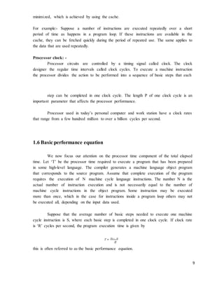
![22
to use instructions in which the locations of all operands are defined implicitly. Such
instructions are found in machines that store operands in a structure called a pushdown
stack. In this case, the instructions are called zero-address instructions.
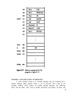
INSTRUCTION EXECUTION AND STRAIGHT-LINE SEQUENCING:-
In the preceding discussion of instruction formats, we used to task C
�[A] +
[B]. fig 2.8 shows a possible program segment for this task as it appears in the memory of
a computer. We have assumed that the computer allows one memory operand per
instruction and has a number of processor registers. The three instructions of the program
are in successive word locations, starting at location i. since each instruction is 4 bytes
long, the second and third instructions start at addresses i + 4 and i + 8.
Address Contents
Let us consider how this program is executed. The processor contains a register
called the program counter (PC), which holds the address of the instruction to be
executed next. To begin executing a program, the address of its first instruction (I in our
example) must be placed into the PC. Then, the processor control circuits use the
information in the PC to fetch and execute instructions, one at a time, in the order of
increasing addresses. This is called straight-line sequencing. During the execution of each](https://image.slidesharecdn.com/conotes3sem-180929072206/85/Co-notes3-sem-22-320.jpg)
![26
addresses to be specified ? The memory operand address cannot be given directly in a
single Add instruction in the loop. Otherwise, it would need to be modified on each pass
through the loop.
The instruction set of a computer typically provides a number of such methods,
called addressing modes. While the details differ from one computer to another, the
underlying concepts are the same.
2.5 Addressing modes:
In general, a program operates on data that reside in the computer’s memory.
These data can be organized in a variety of ways. If we want to keep track of students’
names, we can write them in a list. Programmers use organizations called data structures
to represent the data used in computations. These include lists, linked lists, arrays,
queues, and so on.
Programs are normally written in a high-level language, which enables the
programmer to use constants, local and global variables, pointers, and arrays. The
different ways in which the location of an operand is specified in an instruction are
referred to as addressing modes.
Table 2.1 Generic addressing modes
Name Assembler syntax Addressing function
Immediate # Value Operand = Value
Register
Absolute (Direct)
Ri
LOC
EA = Ri
EA = LOC
Indirect (Ri) EA = [Ri]
(LOC) EA = [LOC]
Index X(Ri) EA = [Ri] + X
Base with index
Base with index
and offset
(Ri, Rj)
X (Ri, Rj)
EA = [Ri] + [Rj]
EA = [Ri] + [Rj] + X
Relative X(PC) EA = [PC] + X
Autoincrement (Ri)+ EA = [Ri]; Increment Ri
Autodecrement -(Ri) Decrement Ri; EA = [Ri]
EA = effective address
Value = a signed number](https://image.slidesharecdn.com/conotes3sem-180929072206/85/Co-notes3-sem-26-320.jpg)
![29
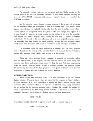
In the program shown Register R2 is used as a pointer to the numbers in the list,
and the operands are accessed indirectly through R2. The initialization section of the
program loads the counter value n from memory location N into R1 and uses the
immediate addressing mode to place the address value NUM1, which is the address of the
first number in the list, into R2. Then it clears R0 to 0. The first two instructions in the
loop implement the unspecified instruction block starting at LOOP. The first time
through the loop, the instruction Add (R2), R0 fetches the operand at location NUM1
and adds it to R0. The second Add instruction adds 4 to the contents of the pointer R2, so
that it will contain the address value NUM2 when the above instruction is executed in the
second pass through the loop.
Where B is a pointer variable. This statement may be compiled into
Move B, R1
Move (R1), A
Using indirect addressing through memory, the same action can be achieved with
Move (B), A
Indirect addressing through registers is used extensively. The above program
shows the flexibility it provides. Also, when absolute addressing is not available, indirect
addressing through registers makes it possible to access global variables by first loading
the operand’s address in a register.
INDEXING AND ARRAYS:-
A different kind of flexibility for accessing operands is useful in dealing with
lists and arrays.
Index mode – the effective address of the operand is generated by adding a constant
value to the contents of a register.
The register use may be either a special register provided for this purpose, or,
more commonly, it may be any one of a set of general-purpose registers in the processor.
In either case, it is referred to as index register. We indicate the Index mode symbolically
as
X (Ri)
Where X denotes the constant value contained in the instruction and Ri is the
name of the register involved. The effective address of the operand is given by
EA = X + [Rj]](https://image.slidesharecdn.com/conotes3sem-180929072206/85/Co-notes3-sem-29-320.jpg)
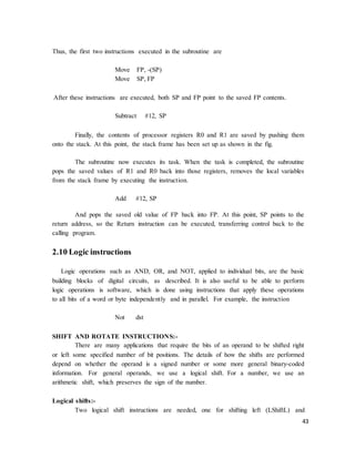
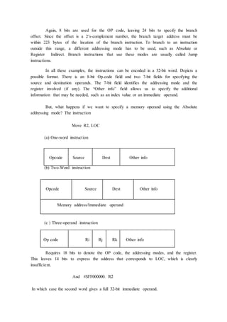
![If we want to allow an instruction in which two operands can be specified using
the Absolute addressing mode, for example
Move LOC1, LOC2
Then it becomes necessary to use tow additional words for the 32-bit addresses of
the operands.
This approach results in instructions of variable length, dependent on the number
of operands and the type of addressing modes used. Using multiple words, we can
implement quite complex instructions, closely resembling operations in high-level
programming languages. The term complex instruction set computer (CISC) has been
used to refer to processors that use instruction sets of this type.
The restriction that an instruction must occupy only one word has led to a style of
computers that have become known as reduced instruction set computer (RISC). The
RISC approach introduced other restrictions, such as that all manipulation of data must be
done on operands that are already in processor registers. This restriction means that the
above addition would need a two-instruction sequence
Move (R3), R1
Add R1, R2
If the Add instruction only has to specify the two registers, it will need just a
portion of a 32-bit word. So, we may provide a more powerful instruction that uses three
operands
Add R1, R2, R3
Which performs the operation
R3 �
[R1] + [R2]
A possible format for such an instruction in shown in fig c. Of course, the
processor has to be able to deal with such three-operand instructions. In an instruction set
where all arithmetic and logical operations use only register operands, the only memory
references are made to load/store the operands into/from the processor registers.
RISC-type instruction sets typically have fewer and less complex instructions
than CISC-type sets. We will discuss the relative merits of RISC and CISC approaches in
Chapter 8, which deals with the details of processor design.](https://image.slidesharecdn.com/conotes3sem-180929072206/85/Co-notes3-sem-49-320.jpg)

This document outlines the syllabus for a course on computer organization. It includes 5 modules that cover topics like basic computer structure, input/output organization, memory systems, arithmetic, and basic processing units. The course aims to explain computer organization and demonstrate how different subsystems like the processor, input/output, and memory function. Students will learn about hardwired and microprogrammed control as well as pipelining, embedded systems, and other computing architectures. Assessment includes assignments, a written exam consisting of questions from each module, and students must answer 1 question from each module.