Memory organization in computer architectureFaisal Hussain
Memory organization in computer architecture
Volatile Memory
Non-Volatile Memory
Memory Hierarchy
Memory Access Methods
Random Access
Sequential Access
Direct Access
Main Memory
DRAM
SRAM
NVRAM
RAM: Random Access Memory
ROM: Read Only Memory
Auxiliary Memory
Cache Memory
Hit Ratio
Associative Memory
(Ref : Computer System Architecture by Morris Mano 3rd edition) : Microprogrammed Control unit, micro instructions, micro operations, symbolic and binary microprogram.
There are situations, called hazards, that prevent the next instruction in the instruction stream from executing during its designated cycle
There are three classes of hazards
Structural hazard
Data hazard
Branch hazard
The presentation given at MSBTE sponsored content updating program on 'PC Maintenance and Troubleshooting' for Diploma Engineering teachers of Maharashtra. Venue: Government Polytechnic, Nashik Date: 17/01/2011 Session-2: Computer Organization and Architecture.
hardwired control is the system level communication in which how the control signal generate by processor with the help of conditional codes, external output and counter circuits
Full information of about CPU register and type of CPU registers,
Use of registers in computer and their basic operation, category of registers and how to use them, flag register.
Addressing mode is the way of addressing a memory location in instruction. Microcontroller needs data or operands on which the operation is to be performed. The method of specifying source of operand and output of result in an instruction is known as addressing mode.
There are various methods of giving source and destination address in instruction, thus there are various types of Addressing Modes. Here you will find the different types of Addressing Modes that are supported in Micro Controller 8051. Types of Addressing Modes are explained below:
1.Register Addressing Mode
2.Direct Addressing Mode
3.Register Indirect Addressing Mode
4.Immediate Addressing Mode
5.Index Addressing Mode
Explanation:
Register Addressing Mode: In this addressing mode, the source of data or destination of result is Register. In this type of addressing mode the name of the register is given in the instruction where the data to be read or result is to be stored.
Example: ADD A, R5 ( The instruction will do the addition of data in Accumulator with data in register R5)
Direct Addressing Mode: In this type of Addressing Mode, the address of data to be read is directly given in the instruction. In case, for storing result the address given in instruction is used to store the result.
Example: MOV A, 46H ( This instruction will move the contents of memory location 46H to Accumulator)
Register Indirect Addressing Mode: In Register Indirect Addressing Mode, as its name suggests the data is read or stored in register indirectly. That is, we provide the register in the instruction, in which the address of the other register is stored or which points to other register where data is stored or to be stored.
Example: MOV A, @R0 ( This instruction will move the data to accumulator from the register whose address is stored in register R0 ).
Also Read: Architecture Of 8051
Immediate Addressing Mode : In Immediate Addressing Mode , the data immediately follows the instruction. This means that data to be used is already given in the instruction itself.
Example: MOV A, #25H ( This instruction will move the data 25H to Accumulator. The # sign shows that preceding term is data, not the address.)
Index Addressing Mode: Offset is added to the base index register to form the effective address if the memory location.This Addressing Mode is used for reading lookup tables in Program Memory. The Address of the exact location of the table is formed by adding the Accumulator Data to the base pointer.
Example: MOVC, @A+DPTR ( This instruction will move the data from the memory to Accumulator; the address is made by adding the contents of Accumulator and Data Pointer.
Please send the answers to my email. Mirre06@hotmail.comSomeone se.pdfebrahimbadushata00
Please send the answers to my email. Mirre06@hotmail.com
Someone sent me wrong answers so please send me correct answers thanks.
1) What is a register? Be precise. Name at least two components in the LMC that meet the
qualications for a register. Name several different kinds of values that a register might hold.
Suppose that the following instructions are found at the given locations in memory:
20
LDA
50
21
ADD
51
50
724
51
006
a. Show the contents of the IR, the PC, the MAR, the MDR, and A at the conclusion of
instruction 20.
b. Show the contents of each register as each step of the fetch–execute cycle is performed for
instruction 21.
3) what is the purpose of the instructions register? What takes the place of the instruction
register in the LMC?
4) What is the explanation for the reasons why programmed IO does not work very well when
the IO device is a hard disk or a graphics display?
5) the x86 series is an example of a CPU architecture. as you are probably aware there are a
number of different chip including the x86 architecture? What word defines the difference
between the various CPUs that share the same architecture? Name at least one different CPU
architecture
20
LDA
50
21
ADD
51
50
724
51
006
Solution
1)The Little Man Computer (LMC) is an instructional model of a computer, created by Dr. Stuart
Madnick in 1965.The LMC is generally used to teach students, because it models a simple von
Neumann architecture computer - which has all of the basic features of a modern computer. It
can be programmed in machine code (albeit in decimal rather than binary) or assembly code.
Register:
In a computer, a register is one of a small set of data holding places that are part of a computer
processor . A register may hold a computer instruction , a storage address, or any kind of data
(such as a bit sequence or individual characters). Some instructions specify registers as part of
the instruction. For example, an instruction may specify that the contents of two defined registers
be added together and then placed in a specified register. A register must be large enough to hold
an instruction - for example, in a 32-bit instruction computer, a register must be 32 bits in length.
In some computer designs, there are smaller registers - for example, half-registers - for shorter
instructions. Depending on the processor design and language rules, registers may be numbered
or have arbitrary names.
Small, permanent storage locations within the CPU used for a particular purpose
Manipulated directly by the Control Unit
Wired for specific function
Size in bits or bytes (not in MB like memory)
Can hold data, an address or an instruction
Use of Registers
Scratchpad for currently executing program
Holds data needed quickly or frequently
Stores information about status of CPU and currently executing program
Address of next program instruction
Signals from external devices
General Purpose Registers
User-visible registers
Hold intermediate results or data values, e.g., l.
based on stored program design
processor system
CPU
memory
input/output system
input/output devices
secondary storage
manages the instruction-execution cycle
FETCH – DECODE – EXECUTE
coordinates the activities of other devices
1.CPU INSTRUCTION AND EXECUTION CYCLEThe primary function of the .pdfaniyathikitchen
1.CPU INSTRUCTION AND EXECUTION CYCLE:
The primary function of the cpu of a computer is to execute the sequence of instructions stored
ina memory which is an external to the cpu.The cpu must first fetch an instruction from the
memory before it can be executed .The sequence of operations involved in processing an
instruction constitutes an instruction cycle.This can be sub divided into two major phases i.e.,
fetch phase and execution phase.These two phases are performed in two cosecutive time slots
under the control of a clock.Hence these two operations are called as cycles .The time needed to
complete the execution of an instruction is known as INSTRUCTION CYCLE time .
a.FETCH CYCLE:The instruction is obtained from main memory during the fetch cycle.The
fetch operation can be described as \"send the address of the next instruction to memory and
recieve the instruction from the memory\".
b.EXECUTION CYCLE:The execution cycle includes decoding the instruction fetching of the
required operand and performing the operations specified by aninstructions opcode.In other
words it can be stated as \"Decode the fetched instruction if the operand is specified in the
memory then fetch that operand and execute the instruction \".
**INSTRUCTION CYCLE:
Thus the fetch and execute operations are carried out in synchronism with a clock is known as
instruction cycle i.e.,IC=FC+EC.
3.a.INSTUCTION FORMAT:Instruction format has one or more number of fields.The first field
is called as operation code field or opcode fielde which indicates type of operations to be
performed by the cpu.It also contains other fields known as operand fields.The cpu executes the
instructions using the information which resides in these fields.
b.WORD SIZE:A memory unit stores binary information in group of bits called words.The
number of bits in each word is often refered to as the WORD SIZE of a computer.Each word is
stored in one memory register.The word size in micro and mini computers ranges from 8 to 32
bits, and large computers usually have 32 or more bits in a word.
c.CLOCK RATE:A clock is a square wave , which is used to synchronize various devices in the
microprocessor and the system.Every microprocessor system requires a clock for its
functioning.The time taken for the microprocessor and the system to execute an instruction is
called clockrate.
4.FUNCTION OF GENERAL PURPOSE AND SPECIAL PURPOSE REGISTERS:
General purpose registers are available to store any transient data required by the program.For
example, when a program is interrupted its state, ie: the value of the registers such as the
program counter, instruction register or memory address register - may be saved into the general
purpose registers, ready for recall when the program is ready to start again.In general the more
registers a CPU has available, the faster it can work.
A Special Function Register (or Special Purpose Register, or simply Special Register) is a
register within a microprocessor, which controls or mon.
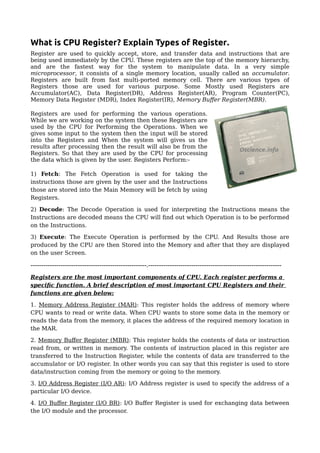
1. What is CPU Register? Explain Types of Register.
Register are used to quickly accept, store, and transfer data and instructions that are
being used immediately by the CPU. These registers are the top of the memory hierarchy,
and are the fastest way for the system to manipulate data. In a very simple
microprocessor, it consists of a single memory location, usually called an accumulator.
Registers are built from fast multi-ported memory cell. There are various types of
Registers those are used for various purpose. Some Mostly used Registers are
Accumulator(AC), Data Register(DR), Address Register(AR), Program Counter(PC),
Memory Data Register (MDR), Index Register(IR), Memory Buffer Register(MBR).
Registers are used for performing the various operations.
While we are working on the system then these Registers are
used by the CPU for Performing the Operations. When we
gives some input to the system then the input will be stored
into the Registers and When the system will gives us the
results after processing then the result will also be from the
Registers. So that they are used by the CPU for processing
the data which is given by the user. Registers Perform:-
1) Fetch: The Fetch Operation is used for taking the
instructions those are given by the user and the Instructions
those are stored into the Main Memory will be fetch by using
Registers.
2) Decode: The Decode Operation is used for interpreting the Instructions means the
Instructions are decoded means the CPU will find out which Operation is to be performed
on the Instructions.
3) Execute: The Execute Operation is performed by the CPU. And Results those are
produced by the CPU are then Stored into the Memory and after that they are displayed
on the user Screen.
------------------------------------------------------.--------------------------------------------------------------
Registers are the most important components of CPU. Each register performs a
specific function. A brief description of most important CPU Registers and their
functions are given below:
1. Memory Address Register (MAR): This register holds the address of memory where
CPU wants to read or write data. When CPU wants to store some data in the memory or
reads the data from the memory, it places the address of the required memory location in
the MAR.
2. Memory Buffer Register (MBR): This register holds the contents of data or instruction
read from, or written in memory. The contents of instruction placed in this register are
transferred to the Instruction Register, while the contents of data are transferred to the
accumulator or I/O register. In other words you can say that this register is used to store
data/instruction coming from the memory or going to the memory.
3. I/O Address Register (I/O AR): I/O Address register is used to specify the address of a
particular I/O device.
4. I/O Buffer Register (I/O BR): I/O Buffer Register is used for exchanging data between
the I/O module and the processor.
2. 5. Program Counter (PC): Program Counter register is also known as Instruction Pointer
Register. This register is used to store the address of the next instruction to be fetched
for execution. When the instruction is fetched, the value of IP is incremented. Thus this
register always points or holds the address of next instruction to be fetched.
6. Instruction Register (IR): Once an instruction is fetched from main memory, it is stored
in the Instruction Register. The control unit takes instruction from this register, decodes
and executes it by sending signals to the appropriate component of computer to carry out
the task.
7. Accumulator Register(AC): The accumulator register is located inside the ALU, It is
used during arithmetic & logical operations of ALU. The control unit stores data values
fetched from main memory in the accumulator for arithmetic or logical operation. This
register holds the initial data to be operated upon, the intermediate results, and the final
result of operation. The final result is transferred to main memory through MBR.
8. Stack Control Register(SCR): A stack represents a set of memory blocks; the data is
stored in and retrieved from these blocks in an order, i.e. First In and Last Out (FILO).
The Stack Control Register is used to manage the stacks in memory. The size of this
register is 2 or 4 bytes.
9. Flag Register(FR): The Flag register is used to indicate occurrence of a certain
condition during an operation of the CPU. It is a special purpose register with size one
byte or two bytes. Each bit of the flag register constitutes a flag (or alarm), such that the
bit value indicates if a specified condition was encountered while executing an
instruction. For example, if zero value is put into an arithmetic register (accumulator) as
a result of an arithmetic operation or a comparison, then the zero flag will be raised by
the CPU. Thus, the subsequent instruction can check this flag and when a zero flag is
"ON" it can take, an appropriate route in the algorithm.
10. Data Register(DR): A register used in microcomputers to temporarily store data being
transmitted to or from a peripheral device.