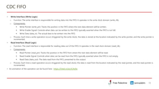
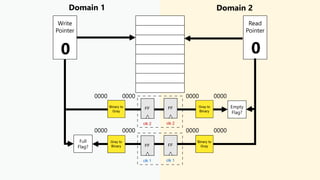
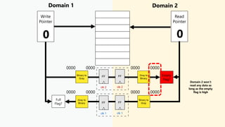
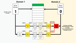
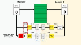
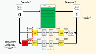
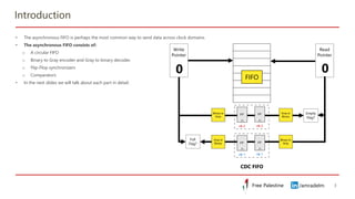
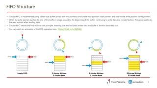
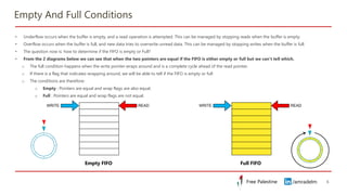
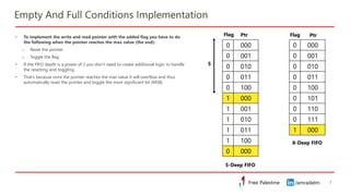
Clock Domain
Crossing
Part 6 – CDC FIFO
Amr Adel Mohammady
/amradelm
/amradelm
/amradelm
/amradelm
Free Palestine
Free Palestine
Introduction
2
• In the previous parts we saw how to send multi-bit data signal using the
mux synchronization scheme.
• Our issue with that scheme is that it’s slow since it requires a handshake
• Our CDC concerns till now:
o Data corruption: Partially fixed. The system can send multi-bit control
signals and data but in a slow manner
o Data incoherence: Fixed. The metastable value settles within the
synchronizers at 0 or 1 and then propagates to all the domain 2 blocks
with the same settled value
o Data loss: Fixed. The pulse is wide enough that it won’t be missed by
domain 2
o Data duplication: Fixed if we use pulse/edge synchronizers
o Chip burning: Fixed. We limited the metastability propagation between
the synchronizers and reduced its occurrence frequency.
• In this part we will see how to send multi-bit data signal using the CDC
FIFO scheme
CDC Handshake Protocol
/amradelm
/amradelm
Free Palestine
Free Palestine
Introduction
3
• The asynchronous FIFO is perhaps the most common way to send data across clock domains.
• The asynchronous FIFO consists of:
o A circular FIFO
o Binary to Gray encoder and Gray to binary decoder.
o Flip-Flop synchronizers
o Comparators
• In the next slides we will talk about each part in detail.
FIFO
CDC FIFO
/amradelm
/amradelm
Free Palestine
Free Palestine
First-In First-Out Buffer
(FIFO)
4
/amradelm
/amradelm
Free Palestine
Free Palestine
FIFO Structure
5
• Circular FIFO is implemented using a fixed-size buffer (array) with two pointers: one for the read position (read pointer) and one for the write position (write pointer).
• When the write pointer reaches the end of the buffer, it wraps around to the beginning of the buffer, continuing to write data in a circular fashion. The same applies to
the read pointer when reading data.
• Circular FIFO follows the First-In-First-Out principle, meaning that the first data written into the buffer is the first data read out.
• You can watch an animation of the FIFO operation here : https://lnkd.in/ezJMAtbG
Empty FIFO 3 Entries Written
0 Entries Read
5 Entries Written
3 Entries Read
9 Entries Written
3 Entries Read
/amradelm
/amradelm
Free Palestine
Free Palestine
Empty And Full Conditions
6
• Underflow occurs when the buffer is empty, and a read operation is attempted. This can be managed by stopping reads when the buffer is empty.
• Overflow occurs when the buffer is full, and new data tries to overwrite unread data. This can be managed by stopping writes when the buffer is full.
• The question now is: how to determine if the FIFO is empty or Full?
• From the 2 diagrams below we can see that when the two pointers are equal if the FIFO is either empty or full but we can’t tell which.
o The full condition happens when the write pointer wraps around and is a complete cycle ahead of the read pointer.
o If there is a flag that indicates wrapping around, we will be able to tell if the FIFO is empty or full
o The conditions are therefore:
o Empty : Pointers are equal and wrap flags are also equal.
o Full : Pointers are equal and wrap flags are not equal.
Empty FIFO Full FIFO
/amradelm
/amradelm
Free Palestine
Free Palestine
Empty And Full Conditions Implementation
7
• To implement the write and read pointer with the added flag you have to do
the following when the pointer reaches the max value (the end):
o Reset the pointer
o Toggle the flag
• If the FIFO depth is a power of 2 you don’t need to create additional logic to handle
the resetting and toggling.
• That’s because once the pointer reaches the max value it will overflow and thus
automatically reset the pointer and toggle the most significant bit (MSB)
0 000
0 001
0 010
0 011
0 100
1 000
1 001
1 010
1 011
1 100
0 000
0 000
0 001
0 010
0 011
0 100
0 101
0 110
0 111
1 000
5-Deep FIFO
8-Deep FIFO
Ptr Ptr
Flag
Flag
5
/amradelm
/amradelm
Free Palestine
Free Palestine
Gray Encoder And Decoder
8
/amradelm
/amradelm
Free Palestine
Free Palestine
Binary to Gray Encoder
9
• Gray code is a binary numeral system where two successive values differ in only one
bit.
• To convert a binary number to its corresponding Gray code:
o The most significant bit (MSB) of the Gray code is the same as the MSB of the
binary input.
o Each subsequent Gray code bit is derived by XOR-ing the corresponding binary
bit with the next higher-order binary bit.
o Example: If binary_in is 3'b101 (binary), then:
▪ gray_out[2] = binary_in[2] = 1
▪ gray_out[1] = binary_in[2] ^ binary_in[1] = 1 ^ 0 = 1
▪ gray_out[0] = binary_in[1] ^ binary_in[0] = 0 ^ 1 = 1
▪ So, gray_out will be 3'b111 (Gray code).
4-Bit Binary to Gray
/amradelm
/amradelm
Free Palestine
Free Palestine
Gray to Binary Decoder
10
• To convert a Gray Code to its corresponding binary code:
o The most significant bit (MSB) of the Gray code is the same as the MSB of the
binary input.
o Each subsequent binary bit is derived by XOR-ing the previous binary bit with the
corresponding Gray code bit.
o Example: If gray_in is 3’b111 (Gray), then:
▪ binary_out[2] = gray_in[2] = 1
▪ binary_out[1] = binary_out[2] ^ gray_in[1] = 1 ^ 1 = 0
▪ binary_out[0] = binary_out[1] ^ gray_in[0] = 0 ^ 1 = 1
▪ So, binary_out will be 3’b101 (binary code).
4-Bit Gray to Binary
/amradelm
/amradelm
Free Palestine
Free Palestine
Verilog Code
11
module gray_to_binary #(
parameter N = 3 // Parameter to define the bit-width,
default is 3
)(
input [N-1:0] gray_in, // N-bit Gray code input
output [N-1:0] binary_out // N-bit binary output
);
// Internal wire to store intermediate results
wire [N-1:0] binary_temp;
// Assigning the MSB directly as it remains the same
assign binary_temp[N-1] = gray_in[N-1];
// Loop to calculate the binary output from Gray code
genvar i;
generate
for (i = N-2; i >= 0; i = i - 1) begin : gray_to_bin
assign binary_temp[i] = binary_temp[i+1] ^
gray_in[i];
end
endgenerate
// Assign the result to output
assign binary_out = binary_temp;
endmodule
module binary_to_gray #(
parameter N = 3 // Parameter to define the bit-width,
default is 3
)(
input [N-1:0] binary_in, // N-bit binary input
output [N-1:0] gray_out // N-bit Gray code output
);
// Assigning the MSB directly as it remains the same
assign gray_out[N-1] = binary_in[N-1];
// Loop to calculate the Gray code output from binary
genvar i;
generate
for (i = N-2; i >= 0; i = i - 1) begin : bin_to_gray
assign gray_out[i] = binary_in[i+1] ^ binary_in[i];
end
endgenerate
endmodule
Binary to Gray Gray to Binary
/amradelm
/amradelm
Free Palestine
Free Palestine
CDC FIFO
12
/amradelm
/amradelm
Free Palestine
Free Palestine
CDC FIFO
13
• Write Interface (Write Logic)
o Function: The write interface is responsible for writing data into the FIFO. It operates in the write clock domain (write_clk).
o Components:
▪ Write Pointer (write_ptr): Tracks the position in the FIFO where the next data element will be written.
▪ Write Enable Signal: Controls when data can be written to the FIFO, typically asserted when the FIFO is not full.
▪ Write Data (data_in): The actual data to be written into the FIFO.
o Process: Each time a write operation occurs (triggered by the write clock), the data is stored at the location indicated by the write pointer, and the write pointer is
incremented.
• Read Interface (Read Logic)
o Function: The read interface is responsible for reading data out of the FIFO. It operates in the read clock domain (read_clk).
o Components:
▪ Read Pointer (read_ptr): Tracks the position in the FIFO from where the next data element will be read.
▪ Read Enable Signal: Controls when data can be read from the FIFO, typically asserted when the FIFO is not empty.
▪ Read Data (data_out): The data read from the FIFO, presented to the output.
o Process: Each time a read operation occurs (triggered by the read clock), the data is read from the location indicated by the read pointer, and the read pointer is
incremented.
• An animation of the operation can be found here : https://lnkd.in/ezUCAx9a
Domain 1 Domain 2
Write
Pointer
Read
Pointer
Empty
Flag?
Full
Flag?
0 0
0000 0000 0000 0000
0000 0000 0000 0000
Domain 1 Domain 2
Write
Pointer
Read
Pointer
Empty
Flag?
Full
Flag?
0 0
0000 0000 0000 0000
0000 0000 0000 0000
Domain 2 won’t
read any data as
long as the empty
flag is high
Domain 1 Domain 2
Write
Pointer
Read
Pointer
Empty
Flag?
Full
Flag?
1 0
0001 0001 0000 0000
0000 0000 0000 0000
The flag is still high
although domain 1 wrote
an entry.
This is due to the latency
through the syncs.
domain 1 wrote
an entry
Domain 1 Domain 2
Write
Pointer
Read
Pointer
Empty
Flag?
Full
Flag?
0 0
1000 1100 1100 1000
0000 0000 0000 0000
Domain 1 won’t write
any data as long as
the full flag is high
Domain 1 Domain 2
Write
Pointer
Read
Pointer
Empty
Flag?
Full
Flag?
0 1
1000 1100 1100 1000
0000 0000 0001 0001
The flag is still high
although domain 2
read an entry.
This is due to the
latency through the
syncs.
Domain 2 read
an entry
Domain 1 Domain 2
Write
Pointer
Read
Pointer
Empty
Flag?
Full
Flag?
1 3
1001 1100 1100 1000
0011 0010 0010 0011
Domain 2 read
another 2 entries
Domain 1 wrote a
new entry.
Write and read can happen simultaneously
/amradelm
/amradelm
Free Palestine
Free Palestine
FIFO Depth
20
• FIFO depth is crucial to prevent data overflow (when the FIFO is too shallow) or underutilization (when the FIFO is too deep).
• The data arrives in bursts (periods of high activity followed by inactivity), the FIFO must be deep enough to hold all the burst data until it can be processed.
• If the write domain writes N data samples within time T and the read domain reads M data samples within the same time we end up with N-M samples that need to
be stored in the FIFO.
• For example if the write domain is 3 times faster than the read domain. For every 3 samples written the slow domain will be able to read only one sample.
• If the write domain write a burst of N samples. The read domain will only read
𝑁
3
samples leaving
2𝑁
3
samples that need to be stored
• The size is therefore calculated as
𝐷𝑒𝑝𝑡ℎ = 𝐵𝑢𝑟𝑠𝑡 − 𝐵𝑢𝑟𝑠𝑡 ×
𝑓𝑟𝑒𝑎𝑑
𝑓𝑤𝑟𝑖𝑡𝑒
𝐷𝑒𝑝𝑡ℎ = 𝐵𝑢𝑟𝑠𝑡 × 1 −
𝑓𝑟𝑒𝑎𝑑
𝑓𝑤𝑟𝑖𝑡𝑒
/amradelm
/amradelm
Free Palestine
Free Palestine
FIFO Depth - Examples
21
https://shorturl.at/qBrGl
• Let 𝒇𝒘𝒓𝒊𝒕𝒆 = 𝟒𝟎𝟎 𝑴𝑯𝒛, 𝒇𝒓𝒆𝒂𝒅 = 𝟏𝟓𝟎 𝑴𝑯𝒛. Burst size = 120. There are no idle cycles between consecutive writes or read operations.
• 𝐷𝑒𝑝𝑡ℎ = 𝐵𝑢𝑟𝑠𝑡 1 −
𝑓𝑟𝑒𝑎𝑑
𝑓𝑤𝑟𝑖𝑡𝑒
= 120 1 −
150
400
= 75 location.
• The size rounded to power of 2 = 128 locations.
• Let 𝒇𝒘𝒓𝒊𝒕𝒆 = 𝟒𝟎𝟎 𝑴𝑯𝒛, 𝒇𝒓𝒆𝒂𝒅 = 𝟏𝟓𝟎 𝑴𝑯𝒛. Burst size = 120. There is 1 idle cycle between consecutive writes.
• The idle cycle will slow down the writing operation giving the read operation more time to read. We should expect the required size to decrease
• With the idle cycle, the write domain takes 2 cycles for each write instead of 1. Effectively the frequency is halved.
• 𝐷𝑒𝑝𝑡ℎ = 𝐵𝑢𝑟𝑠𝑡 1 −
𝑓𝑟𝑒𝑎𝑑
𝑓𝑤𝑟𝑖𝑡𝑒/𝟐
= 120 1 −
150
400/2
= 30 location.
• The size rounded to power of 2 = 32 locations.
• More examples can be found in this document by Putta Satish : https://shorturl.at/qBrGl
/amradelm
/amradelm
Free Palestine
Free Palestine
References
22
1) http://www.sunburst-design.com/papers/CummingsSNUG2008Boston_CDC.pdf
2) https://www.uio.no/studier/emner/matnat/ifi/IN3160/v21/timeplan/in3160-l92-clock-domains.pdf
3) https://ieeexplore.ieee.org/document/1676187
4) https://www.edn.com/keep-metastability-from-killing-your-digital-design/
5) https://people.ece.ubc.ca/~edc/7660.jan2018/lec11.pdf
6) https://www.onsemi.com/pub/Collateral/AN1504-D.PDF
/amradelm
/amradelm
Free Palestine
Free Palestine
Thank You!
23

Clock Domain Crossing Part 6 - Asynchronous FIFO

  • 1.
    Clock Domain Crossing Part 6– CDC FIFO Amr Adel Mohammady /amradelm /amradelm
  • 2.
    /amradelm /amradelm Free Palestine Free Palestine Introduction 2 •In the previous parts we saw how to send multi-bit data signal using the mux synchronization scheme. • Our issue with that scheme is that it’s slow since it requires a handshake • Our CDC concerns till now: o Data corruption: Partially fixed. The system can send multi-bit control signals and data but in a slow manner o Data incoherence: Fixed. The metastable value settles within the synchronizers at 0 or 1 and then propagates to all the domain 2 blocks with the same settled value o Data loss: Fixed. The pulse is wide enough that it won’t be missed by domain 2 o Data duplication: Fixed if we use pulse/edge synchronizers o Chip burning: Fixed. We limited the metastability propagation between the synchronizers and reduced its occurrence frequency. • In this part we will see how to send multi-bit data signal using the CDC FIFO scheme CDC Handshake Protocol
  • 3.
    /amradelm /amradelm Free Palestine Free Palestine Introduction 3 •The asynchronous FIFO is perhaps the most common way to send data across clock domains. • The asynchronous FIFO consists of: o A circular FIFO o Binary to Gray encoder and Gray to binary decoder. o Flip-Flop synchronizers o Comparators • In the next slides we will talk about each part in detail. FIFO CDC FIFO
  • 4.
  • 5.
    /amradelm /amradelm Free Palestine Free Palestine FIFOStructure 5 • Circular FIFO is implemented using a fixed-size buffer (array) with two pointers: one for the read position (read pointer) and one for the write position (write pointer). • When the write pointer reaches the end of the buffer, it wraps around to the beginning of the buffer, continuing to write data in a circular fashion. The same applies to the read pointer when reading data. • Circular FIFO follows the First-In-First-Out principle, meaning that the first data written into the buffer is the first data read out. • You can watch an animation of the FIFO operation here : https://lnkd.in/ezJMAtbG Empty FIFO 3 Entries Written 0 Entries Read 5 Entries Written 3 Entries Read 9 Entries Written 3 Entries Read
  • 6.
    /amradelm /amradelm Free Palestine Free Palestine EmptyAnd Full Conditions 6 • Underflow occurs when the buffer is empty, and a read operation is attempted. This can be managed by stopping reads when the buffer is empty. • Overflow occurs when the buffer is full, and new data tries to overwrite unread data. This can be managed by stopping writes when the buffer is full. • The question now is: how to determine if the FIFO is empty or Full? • From the 2 diagrams below we can see that when the two pointers are equal if the FIFO is either empty or full but we can’t tell which. o The full condition happens when the write pointer wraps around and is a complete cycle ahead of the read pointer. o If there is a flag that indicates wrapping around, we will be able to tell if the FIFO is empty or full o The conditions are therefore: o Empty : Pointers are equal and wrap flags are also equal. o Full : Pointers are equal and wrap flags are not equal. Empty FIFO Full FIFO
  • 7.
    /amradelm /amradelm Free Palestine Free Palestine EmptyAnd Full Conditions Implementation 7 • To implement the write and read pointer with the added flag you have to do the following when the pointer reaches the max value (the end): o Reset the pointer o Toggle the flag • If the FIFO depth is a power of 2 you don’t need to create additional logic to handle the resetting and toggling. • That’s because once the pointer reaches the max value it will overflow and thus automatically reset the pointer and toggle the most significant bit (MSB) 0 000 0 001 0 010 0 011 0 100 1 000 1 001 1 010 1 011 1 100 0 000 0 000 0 001 0 010 0 011 0 100 0 101 0 110 0 111 1 000 5-Deep FIFO 8-Deep FIFO Ptr Ptr Flag Flag 5
  • 8.
  • 9.
    /amradelm /amradelm Free Palestine Free Palestine Binaryto Gray Encoder 9 • Gray code is a binary numeral system where two successive values differ in only one bit. • To convert a binary number to its corresponding Gray code: o The most significant bit (MSB) of the Gray code is the same as the MSB of the binary input. o Each subsequent Gray code bit is derived by XOR-ing the corresponding binary bit with the next higher-order binary bit. o Example: If binary_in is 3'b101 (binary), then: ▪ gray_out[2] = binary_in[2] = 1 ▪ gray_out[1] = binary_in[2] ^ binary_in[1] = 1 ^ 0 = 1 ▪ gray_out[0] = binary_in[1] ^ binary_in[0] = 0 ^ 1 = 1 ▪ So, gray_out will be 3'b111 (Gray code). 4-Bit Binary to Gray
  • 10.
    /amradelm /amradelm Free Palestine Free Palestine Grayto Binary Decoder 10 • To convert a Gray Code to its corresponding binary code: o The most significant bit (MSB) of the Gray code is the same as the MSB of the binary input. o Each subsequent binary bit is derived by XOR-ing the previous binary bit with the corresponding Gray code bit. o Example: If gray_in is 3’b111 (Gray), then: ▪ binary_out[2] = gray_in[2] = 1 ▪ binary_out[1] = binary_out[2] ^ gray_in[1] = 1 ^ 1 = 0 ▪ binary_out[0] = binary_out[1] ^ gray_in[0] = 0 ^ 1 = 1 ▪ So, binary_out will be 3’b101 (binary code). 4-Bit Gray to Binary
  • 11.
    /amradelm /amradelm Free Palestine Free Palestine VerilogCode 11 module gray_to_binary #( parameter N = 3 // Parameter to define the bit-width, default is 3 )( input [N-1:0] gray_in, // N-bit Gray code input output [N-1:0] binary_out // N-bit binary output ); // Internal wire to store intermediate results wire [N-1:0] binary_temp; // Assigning the MSB directly as it remains the same assign binary_temp[N-1] = gray_in[N-1]; // Loop to calculate the binary output from Gray code genvar i; generate for (i = N-2; i >= 0; i = i - 1) begin : gray_to_bin assign binary_temp[i] = binary_temp[i+1] ^ gray_in[i]; end endgenerate // Assign the result to output assign binary_out = binary_temp; endmodule module binary_to_gray #( parameter N = 3 // Parameter to define the bit-width, default is 3 )( input [N-1:0] binary_in, // N-bit binary input output [N-1:0] gray_out // N-bit Gray code output ); // Assigning the MSB directly as it remains the same assign gray_out[N-1] = binary_in[N-1]; // Loop to calculate the Gray code output from binary genvar i; generate for (i = N-2; i >= 0; i = i - 1) begin : bin_to_gray assign gray_out[i] = binary_in[i+1] ^ binary_in[i]; end endgenerate endmodule Binary to Gray Gray to Binary
  • 12.
  • 13.
    /amradelm /amradelm Free Palestine Free Palestine CDCFIFO 13 • Write Interface (Write Logic) o Function: The write interface is responsible for writing data into the FIFO. It operates in the write clock domain (write_clk). o Components: ▪ Write Pointer (write_ptr): Tracks the position in the FIFO where the next data element will be written. ▪ Write Enable Signal: Controls when data can be written to the FIFO, typically asserted when the FIFO is not full. ▪ Write Data (data_in): The actual data to be written into the FIFO. o Process: Each time a write operation occurs (triggered by the write clock), the data is stored at the location indicated by the write pointer, and the write pointer is incremented. • Read Interface (Read Logic) o Function: The read interface is responsible for reading data out of the FIFO. It operates in the read clock domain (read_clk). o Components: ▪ Read Pointer (read_ptr): Tracks the position in the FIFO from where the next data element will be read. ▪ Read Enable Signal: Controls when data can be read from the FIFO, typically asserted when the FIFO is not empty. ▪ Read Data (data_out): The data read from the FIFO, presented to the output. o Process: Each time a read operation occurs (triggered by the read clock), the data is read from the location indicated by the read pointer, and the read pointer is incremented. • An animation of the operation can be found here : https://lnkd.in/ezUCAx9a
  • 14.
    Domain 1 Domain2 Write Pointer Read Pointer Empty Flag? Full Flag? 0 0 0000 0000 0000 0000 0000 0000 0000 0000
  • 15.
    Domain 1 Domain2 Write Pointer Read Pointer Empty Flag? Full Flag? 0 0 0000 0000 0000 0000 0000 0000 0000 0000 Domain 2 won’t read any data as long as the empty flag is high
  • 16.
    Domain 1 Domain2 Write Pointer Read Pointer Empty Flag? Full Flag? 1 0 0001 0001 0000 0000 0000 0000 0000 0000 The flag is still high although domain 1 wrote an entry. This is due to the latency through the syncs. domain 1 wrote an entry
  • 17.
    Domain 1 Domain2 Write Pointer Read Pointer Empty Flag? Full Flag? 0 0 1000 1100 1100 1000 0000 0000 0000 0000 Domain 1 won’t write any data as long as the full flag is high
  • 18.
    Domain 1 Domain2 Write Pointer Read Pointer Empty Flag? Full Flag? 0 1 1000 1100 1100 1000 0000 0000 0001 0001 The flag is still high although domain 2 read an entry. This is due to the latency through the syncs. Domain 2 read an entry
  • 19.
    Domain 1 Domain2 Write Pointer Read Pointer Empty Flag? Full Flag? 1 3 1001 1100 1100 1000 0011 0010 0010 0011 Domain 2 read another 2 entries Domain 1 wrote a new entry. Write and read can happen simultaneously
  • 20.
    /amradelm /amradelm Free Palestine Free Palestine FIFODepth 20 • FIFO depth is crucial to prevent data overflow (when the FIFO is too shallow) or underutilization (when the FIFO is too deep). • The data arrives in bursts (periods of high activity followed by inactivity), the FIFO must be deep enough to hold all the burst data until it can be processed. • If the write domain writes N data samples within time T and the read domain reads M data samples within the same time we end up with N-M samples that need to be stored in the FIFO. • For example if the write domain is 3 times faster than the read domain. For every 3 samples written the slow domain will be able to read only one sample. • If the write domain write a burst of N samples. The read domain will only read 𝑁 3 samples leaving 2𝑁 3 samples that need to be stored • The size is therefore calculated as 𝐷𝑒𝑝𝑡ℎ = 𝐵𝑢𝑟𝑠𝑡 − 𝐵𝑢𝑟𝑠𝑡 × 𝑓𝑟𝑒𝑎𝑑 𝑓𝑤𝑟𝑖𝑡𝑒 𝐷𝑒𝑝𝑡ℎ = 𝐵𝑢𝑟𝑠𝑡 × 1 − 𝑓𝑟𝑒𝑎𝑑 𝑓𝑤𝑟𝑖𝑡𝑒
  • 21.
    /amradelm /amradelm Free Palestine Free Palestine FIFODepth - Examples 21 https://shorturl.at/qBrGl • Let 𝒇𝒘𝒓𝒊𝒕𝒆 = 𝟒𝟎𝟎 𝑴𝑯𝒛, 𝒇𝒓𝒆𝒂𝒅 = 𝟏𝟓𝟎 𝑴𝑯𝒛. Burst size = 120. There are no idle cycles between consecutive writes or read operations. • 𝐷𝑒𝑝𝑡ℎ = 𝐵𝑢𝑟𝑠𝑡 1 − 𝑓𝑟𝑒𝑎𝑑 𝑓𝑤𝑟𝑖𝑡𝑒 = 120 1 − 150 400 = 75 location. • The size rounded to power of 2 = 128 locations. • Let 𝒇𝒘𝒓𝒊𝒕𝒆 = 𝟒𝟎𝟎 𝑴𝑯𝒛, 𝒇𝒓𝒆𝒂𝒅 = 𝟏𝟓𝟎 𝑴𝑯𝒛. Burst size = 120. There is 1 idle cycle between consecutive writes. • The idle cycle will slow down the writing operation giving the read operation more time to read. We should expect the required size to decrease • With the idle cycle, the write domain takes 2 cycles for each write instead of 1. Effectively the frequency is halved. • 𝐷𝑒𝑝𝑡ℎ = 𝐵𝑢𝑟𝑠𝑡 1 − 𝑓𝑟𝑒𝑎𝑑 𝑓𝑤𝑟𝑖𝑡𝑒/𝟐 = 120 1 − 150 400/2 = 30 location. • The size rounded to power of 2 = 32 locations. • More examples can be found in this document by Putta Satish : https://shorturl.at/qBrGl
  • 22.
    /amradelm /amradelm Free Palestine Free Palestine References 22 1)http://www.sunburst-design.com/papers/CummingsSNUG2008Boston_CDC.pdf 2) https://www.uio.no/studier/emner/matnat/ifi/IN3160/v21/timeplan/in3160-l92-clock-domains.pdf 3) https://ieeexplore.ieee.org/document/1676187 4) https://www.edn.com/keep-metastability-from-killing-your-digital-design/ 5) https://people.ece.ubc.ca/~edc/7660.jan2018/lec11.pdf 6) https://www.onsemi.com/pub/Collateral/AN1504-D.PDF
  • 23.