The document summarizes key differences between the CPU-memory subsystem and the input-output (I/O) subsystem.
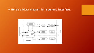
The CPU-memory subsystem has predictable, fast transaction times between tightly integrated components. In contrast, the I/O subsystem has variable transaction times with non-random access devices that are more distant from the CPU. I/O interfaces translate between devices' analog and digital signals and provide buffers to reduce CPU workload for data transfers. Interfaces conform to bus standards to facilitate communication between the wide variety of I/O devices and the CPU over different distances and speeds.