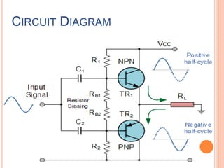
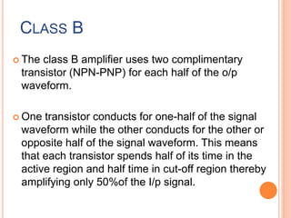
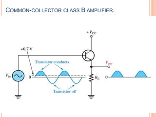
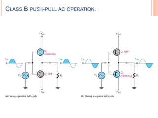
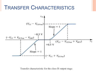
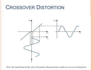
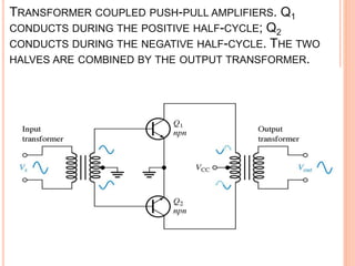
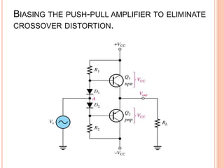
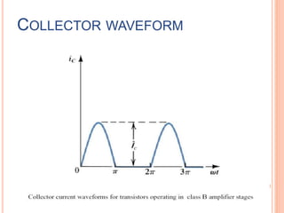
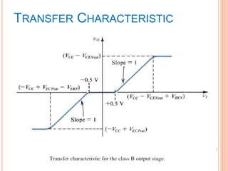
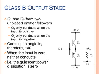
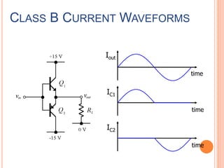
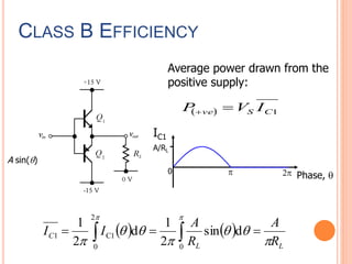
CLASS B
AMPLIFIER
Gauravsinh Parmar
(170410117023)
Neel Patel
(170410117033)
CLASS B AMPLIFIER
 Class B amplifier is a type of power amplifier
where the active device (transistor) conducts
only for one half cycle of the input signal. That
means the conduction angle is 180° for a Class B
amplifier. Since the active device is switched off
for half the input cycle, the active device
dissipates less power and hence the efficiency is
improved.
 Theoretical maximum efficiency of Class B
power amplifier is 78.5%. The schematic of a
single ended Class B amplifier and input , output
waveforms are shown
CIRCUIT DIAGRAM
CLASS B
 The class B amplifier uses two complimentary
transistor (NPN-PNP) for each half of the o/p
waveform.
 One transistor conducts for one-half of the signal
waveform while the other conducts for the other or
opposite half of the signal waveform. This means
that each transistor spends half of its time in the
active region and half time in cut-off region thereby
amplifying only 50%of the I/p signal.
COMMON-COLLECTOR CLASS B AMPLIFIER.
CLASS B PUSH-PULL AC OPERATION.
TRANSFER CHARACTERISTICS
CROSSOVER DISTORTION
TRANSFORMER COUPLED PUSH-PULL AMPLIFIERS. Q1
CONDUCTS DURING THE POSITIVE HALF-CYCLE; Q2
CONDUCTS DURING THE NEGATIVE HALF-CYCLE. THE TWO
HALVES ARE COMBINED BY THE OUTPUT TRANSFORMER.
BIASING THE PUSH-PULL AMPLIFIER TO ELIMINATE
CROSSOVER DISTORTION.
COLLECTOR WAVEFORM
TRANSFER CHARACTERISTIC
CLASS B OUTPUT STAGE
 Q1 and Q2 form two
unbiased emitter followers
 Q1 only conducts when the
input is positive
 Q2 only conducts when the
input is negative
 Conduction angle is,
therefore, 180°
 When the input is zero,
neither conducts
 i.e. the quiescent power
dissipation is zero
CLASS B CURRENT WAVEFORMS
Iout
IC1
IC2
time
time
time
CLASS B EFFICIENCY
Average power drawn from the
positive supply:
IC1
Phase, q
A/RL
0 p 2p
A sin(q)
   
LL
C
R
A
R
A
II
p
qq
p
qq
p
pp
  0
2
0
C11 dsin
2
1
d
2
1
  1CSve IVP 
EFFICIENCY / POWER DISSIPATION
Peak efficiency of the class B output stage is
78.5 %, much higher than class A.
Unlike class A, power dissipation varies with
output amplitude.
Remember, there are two output devices so
the power dissipation is shared between
them.
CLASS B
Class B amplifiers are used in low cost
designs or designs where sound quality is not
that important.
Class B amplifiers are significantly more
efficient than class A amps.
They suffer from bad distortion when the signal
level is low (the distortion in this region of
operation is called "crossover distortion").
ADVANTAGES
 The Collector efficiency quite high due to class B
operation.
 Distortion free o/p is obtained, they give more ac
o/p power. They are light in weight.
 o/p transformer use to push pull amplifier circuit
are light, smaller and less expensive.
DISADVANTAGES
Two identical transformer required.
It required two equal and opposite voltage at
the I/p.
If the parameter of the two transistor differ,
there’ll be unequal amplification of the two
halves of the signal which introduce more
distortion.

Class b amplifier

  • 1.
  • 2.
    CLASS B AMPLIFIER Class B amplifier is a type of power amplifier where the active device (transistor) conducts only for one half cycle of the input signal. That means the conduction angle is 180° for a Class B amplifier. Since the active device is switched off for half the input cycle, the active device dissipates less power and hence the efficiency is improved.  Theoretical maximum efficiency of Class B power amplifier is 78.5%. The schematic of a single ended Class B amplifier and input , output waveforms are shown
  • 3.
  • 4.
    CLASS B  Theclass B amplifier uses two complimentary transistor (NPN-PNP) for each half of the o/p waveform.  One transistor conducts for one-half of the signal waveform while the other conducts for the other or opposite half of the signal waveform. This means that each transistor spends half of its time in the active region and half time in cut-off region thereby amplifying only 50%of the I/p signal.
  • 5.
  • 6.
    CLASS B PUSH-PULLAC OPERATION.
  • 7.
  • 8.
  • 9.
    TRANSFORMER COUPLED PUSH-PULLAMPLIFIERS. Q1 CONDUCTS DURING THE POSITIVE HALF-CYCLE; Q2 CONDUCTS DURING THE NEGATIVE HALF-CYCLE. THE TWO HALVES ARE COMBINED BY THE OUTPUT TRANSFORMER.
  • 10.
    BIASING THE PUSH-PULLAMPLIFIER TO ELIMINATE CROSSOVER DISTORTION.
  • 11.
  • 12.
  • 13.
    CLASS B OUTPUTSTAGE  Q1 and Q2 form two unbiased emitter followers  Q1 only conducts when the input is positive  Q2 only conducts when the input is negative  Conduction angle is, therefore, 180°  When the input is zero, neither conducts  i.e. the quiescent power dissipation is zero
  • 14.
    CLASS B CURRENTWAVEFORMS Iout IC1 IC2 time time time
  • 15.
    CLASS B EFFICIENCY Averagepower drawn from the positive supply: IC1 Phase, q A/RL 0 p 2p A sin(q)     LL C R A R A II p qq p qq p pp   0 2 0 C11 dsin 2 1 d 2 1   1CSve IVP 
  • 16.
    EFFICIENCY / POWERDISSIPATION Peak efficiency of the class B output stage is 78.5 %, much higher than class A. Unlike class A, power dissipation varies with output amplitude. Remember, there are two output devices so the power dissipation is shared between them.
  • 17.
    CLASS B Class Bamplifiers are used in low cost designs or designs where sound quality is not that important. Class B amplifiers are significantly more efficient than class A amps. They suffer from bad distortion when the signal level is low (the distortion in this region of operation is called "crossover distortion").
  • 18.
    ADVANTAGES  The Collectorefficiency quite high due to class B operation.  Distortion free o/p is obtained, they give more ac o/p power. They are light in weight.  o/p transformer use to push pull amplifier circuit are light, smaller and less expensive.
  • 19.
    DISADVANTAGES Two identical transformerrequired. It required two equal and opposite voltage at the I/p. If the parameter of the two transistor differ, there’ll be unequal amplification of the two halves of the signal which introduce more distortion.