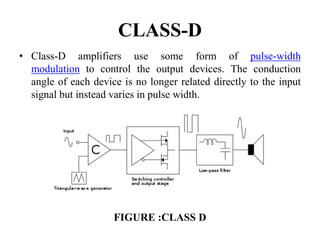
2. INTRODUCTION
• An amplifier, electronic amplifier or (informally) amp is an
electronic device that can increase the power of a signal (a
time-varying voltage or current). An amplifier uses
electric power from a power supply to increase the amplitude
of a signal.An amplifier is a circuit that has a power gain
greater than one.
• It does this by taking energy from a power supply and
controlling the output to match the input signal shape but with
a larger amplitude. In this sense, an amplifier modulates the
output of the power supply.
• Numerous types of electronic amplifiers are specialized to
various applications.
• An amplifier can refer to anything from an electrical circuit
that uses a single active component, to a complete system such
as a packaged audio hi-fi amplifier.
3. POWER AMPLIFIER
• The term power amplifier is a relative term with
respect to the amount of power delivered to the load
and/or sourced by the supply circuit.
• In general a power amplifier is designated as the last
amplifier in a transmission chain (the output stage)
and is the amplifier stage that typically requires most
attention to power efficiency.
• Efficiency considerations lead to various classes of
power amplifier based on the biasing of the output
transistors or tubes.
4. POWER AMPLIFIER CLASSES
• The classes are related to the time period that the active
amplifier device is passing current, expressed as a fraction of
the period of a signal waveform applied to the input.
• Power amplifier circuits (output stages) are classified as A, B,
AB and C for analog designs, and class D for switching
designs based on the proportion of each input cycle
(conduction angle), during which an amplifying device is
passing current.
5. Class A
• 100% of the input signal is used (conduction angle Θ = 360°.
The active element remains conducting all of the time.
• Amplifying devices operating in class A conduct over the
whole of the input cycle.
• A class-A amplifier is distinguished by the output stage being
biased into class A (see definition above).
Figure: Class A
6. Advantages of class-A amplifiers
• Class-A designs can be simpler than other classes insofar as
class -AB and -B designs require two connected devices in the
circuit (push–pull output), each to handle one half of the
waveform whereas class A can use a single device (single-
ended).
• The amplifying element is biased so the device is always
conducting, the quiescent (small-signal) collector current
(for transistors; drain current for FETs or anode/plate current
for vacuum tubes) is close to the most linear portion of
its transconductance curve.
• Because the device is never 'off' there is no "turn on" time, no
problems with charge storage, and generally better high
frequency performance and feedback loop stability (and
usually fewer high-order harmonics).
7. • The point where the device comes closest to being 'off' is not
at 'zero signal', so the problems of crossover
distortion associated with class-AB and -B designs is avoided.
• Best for low signal levels of radio receivers due to low
distortion.
8. Disadvantages of class-A amplifiers
• Class-A amplifiers are inefficient. A maximum theoretical
efficiency of 25% is obtainable using usual configurations, but
50% is the maximum for a transformer or inductively coupled
configuration.
• In a power amplifier, this not only wastes power and limits
operation with batteries, but increases operating costs and
requires higher-rated output devices.
• Inefficiency comes from the standing current that must be
roughly half the maximum output current, and a large part of the
power supply voltage is present across the output device at low
signal levels.
• If high output power is needed from a class-A circuit, the power
supply and accompanying heat becomes significant.
9. CLASS B
• Class-B amplifiers only amplify half of the input wave cycle,
thus creating a large amount of distortion, but their efficiency
is greatly improved and is much better than class A.
• A single class-B element is rarely found in practice, though it
has been used for driving the loudspeaker in the early IBM
Personal Computers with beeps, and it can be used in RF
power amplifier where the distortion levels are less important.
However, class C is more commonly used for this.
• Class-B amplifiers are also favored in battery-operated
devices, such as transistor radios.
• Class B has a maximum theoretical efficiency of π/4. (i.e.
78.5%)
10. • A single class-B element is rarely found in practice, though it
has been used for driving the loudspeaker in the early IBM
Personal Computers with beeps, and it can be used in RF
power amplifier where the distortion levels are less important.
FIGURE : CLASS B
11. CLASS AB
• Class AB is widely considered a good compromise for audio
power amplifiers, since much of the time the music is quiet
enough that the signal stays in the "class A" region, where it is
amplified with good fidelity, and by definition if passing out of
this region, is large enough that the distortion products typical
of class B are relatively small.
• In class-AB operation, each device operates the same way as
in class B over half the waveform, but also conducts a small
amount on the other half.
• As a result, the region where both devices simultaneously are
nearly off (the "dead zone") is reduced. The result is that when
the waveforms from the two devices are combined, the
crossover is greatly minimised or eliminated altogether.
12. • Class AB sacrifices some efficiency over class B in favor of
linearity, thus is less efficient (below 78.5% for full-
amplitude sine waves in transistor amplifiers, typically; much
less is common in class-AB vacuum-tube amplifiers). It is
typically much more efficient than class A.
FIGURE: CLASS AB
13. CLASS-C
• Class-C amplifiers conduct less than 50% of the input signal
and the distortion at the output is high, but high efficiencies
(up to 90%) are possible.
• The usual application for class-C amplifiers is in RF
transmitters operating at a single fixed carrier frequency,
where the distortion is controlled by a tuned load on the
amplifier.
• The class-C amplifier has two modes of operation: tuned and
untuned.The diagram shows a waveform from a simple class-
C circuit without the tuned load. This is called untuned
operation, and the analysis of the waveforms shows the
massive distortion that appears in the signal. When the proper
load (e.g., an inductive-capacitive filter plus a load resistor) is
used, two things happen.
14. • The first is that the output's bias level is clamped with the
average output voltage equal to the supply voltage. This is why
tuned operation is sometimes called a clamper. This restores
the waveform to its proper shape, despite the amplifier having
only a one-polarity supply. This is directly related to the
second phenomenon: the waveform on the center frequency
becomes less distorted. The residual distortion is dependent
upon the bandwidth of the tuned load, with the center
frequency seeing very little distortion, but greater attenuation
the farther from the tuned frequency that the signal gets.
• The tuned circuit resonates at one frequency, the fixed carrier
frequency, and so the unwanted frequencies are suppressed,
and the wanted full signal (sine wave) is extracted by the tuned
load. The signal bandwidth of the amplifier is limited by
the Q-factor of the tuned circuit but this is not a serious
limitation. Any residual harmonics can be removed using a
further filter.
15. • Ideally, the active element would pass only an instantaneous
current pulse while the voltage across it is zero: it then
dissipates no power and 100% efficiency is achieved.
FIGURE: CLASS C
16. CLASS-D
• Class-D amplifiers use some form of pulse-width
modulation to control the output devices. The conduction
angle of each device is no longer related directly to the input
signal but instead varies in pulse width.
FIGURE :CLASS D
17. • The main advantage of a class-D amplifier is power efficiency.
Because the output pulses have a fixed amplitude, the
switching elements (usually MOSFETs, but vacuum tubes, and
at one time bipolar transistors, were used) are switched either
completely on or completely off, rather than operated in linear
mode.
• Another advantage of the class-D amplifier is that it can
operate from a digital signal source without requiring a digital-
to-analog converter (DAC) to convert the signal to analog
form first.