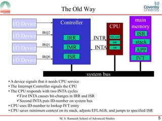
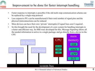
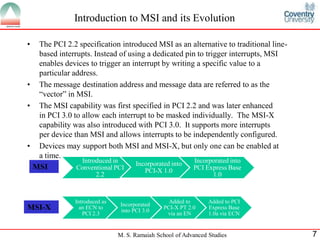
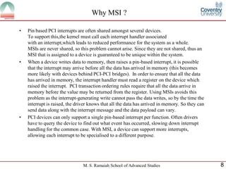
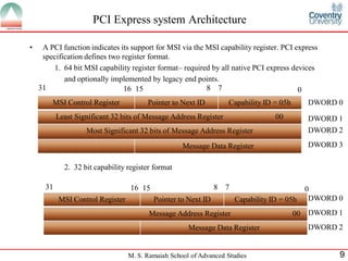
1) The document discusses Message Signaled Interrupts (MSI), an improvement over the traditional interrupt handling method. MSI allows interrupt information to be delivered in one step from a device directly to the CPU.
2) MSI was introduced in PCI 2.2 and improved in PCI 3.0 with MSI-X, which supports more interrupts per device. MSI uses a memory write to trigger an interrupt, while traditional interrupts use dedicated pins.
3) The benefits of MSI include faster response, less hardware requirements, guarantee of unique interrupts, and ability to send data with the interrupt. MSI also avoids ordering issues with traditional interrupts.
Architecture Exploration of RISC-V Processor and Comparison with ARM Cortex-A53KarthiSugumar
This presentation focuses on the architectural exploration of RISC-V ISA based processor for networking applications such as a Router, using the trade-off between power consumption and performance. The optimized architecture is compared against commercially available RISC processors from ARM. A model of RISC-V based Solid-State Drive is also proposed.
XPDDS17: Reworking the ARM GIC Emulation & Xen Challenges in the ARM ITS Emu...The Linux Foundation
Part 1: Reworking the ARM GIC Emulation
The ARM Generic Interrupt Controller (GIC) provides some level of virtualization support in hardware. This still requires emulation of the distributor part, which has to integrate with the virtualization feature. Doing this in a performing and readable way is not trivial, especially the locking strategy tends to be complicated.
While extending the existing virtual GIC support in Xen to cover support for MSIs, some issues have been discovered which ask for some significant changes in the existing code.
The presentation will briefly describe the existing VGIC design and the issues we faced when trying to extend it. Based on this the changes will be presented and how they improve and ideally simplify the code.
Part 2: Xen Challenges in the ARM ITS Emulation
For being able to use MSIs on ARM systems in Xen domains we need to emulate the ARM GICv3 ITS controller. Its design is centered around a command queue located in normal system memory.
Emulating this in the Xen hypervisor brings some interesting challenges, ranging from safely accessing the guest memory and dealing with possible propagation of commands, to possible DOS attacks by domains keeping the emulation code busy.
The presentation outlines the main problems and how we hit Xen limits in emulating this correctly and efficiently. Also it presents our temporary workarounds and their drawbacks.
Physician entrepreneurship and app development: business model lessons. First given at Medicine 2.0 Meeting at Harvard Medical School September 15, 2012.
Come check out Multi-Peer Connectivity, a brand new framework for connecting multiple devices in a peer-to-peer network. We'll learn how to get a basic application up and running and take advantage of these new APIs to create a whole new interactive dynamic in your apps.
Pervasive computing also known as Ubiquitous computing (ubicomp) is a concept in software engineering and computer science where computing is made to appear everywhere and anywhere. Eg:laptop computers, tablets and terminals in everyday objects such as a fridge or a pair of glasses.
•It is also termed as ambient intelligence, Ubiquitous computing ,everyware,physical computing, the Internet of Things, haptic computing, and 'things that think’.
An open, unencrypted wireless network can 'sniff' or capture and record the traffic, gain unauthorized access to internal network resources as well as to the internet, and then use the information and resources to perform disruptive or illegal acts.Many laptop computers have wireless cards pre-installed. The ability to enter a network while mobile has great benefits. However, wireless networking is prone to some security. Wireless networks relatively easy to break into, and even use wireless technology to hack into wired networks.The risks to users of wireless technology have increased as the service has become more popular.As a result, it is very important that enterprises define effective wireless security policies that guard against unauthorized access to important resources.
Interconnection Network
in this presentation there are some explain to Interconnection Network , and espically in computer architecture and parallel processing.
SNMP is a tool (protocol) that allows for remote and local management of items on the network including servers, workstations, routers, switches and other managed devices.
•It is an application level protocol and is designed for application layer so that it can monitor devices made by different manufacturers and installed on different physical networks.
•In other words SNMP frees management tasks from both the physical characteristics of managed devices and the underlying network technology.
•It is based on the concept of manager and agent.
–Agent - process running on each managed node collecting information about the device it is running on. It is a router or a host that runs SNMP server program
–Manager - process running on a management workstation that requests information about devices on the network. It is a host that runs the SNMP client program.
Microprocessor architecture,
Organisation & operation of microcomputer systems.
Hardware and software interaction.
Programme and data storage.
Parallel interfacing and programmable ICs.
Serial interfacing, standards and protocols.
Analogue interfacing. Interrupts and DMA.
Microcontrollers and small embedded systems.
The CPU, memory and the operating system.
An advanced processor is a type of microprocessor that is designed to handle complex tasks and perform calculations at a high speed. These processors are typically used in high-performance computing applications, such as scientific research, artificial intelligence, and data analysis. They often have multiple cores and advanced instruction sets that allow them to process large amounts of data quickly and efficiently. Some examples of advanced processors include Intel's Core i9 and AMD's Ryzen Threadripper
this is a complete summer training report on embedded sys_AVR. It aslo includes a project and its coding and other topics which are learnt in training.
Micro controller and dsp processor, Microcontroller, What is Microcontroller , Features of a Microcontroller, Types of Microcontrollers, cisc, risc, Comparison between RISC and CISC, Harvard Memory Architecture Microcontroller, Von Neumann or Princeton Memory Architecture Microcontroller, External memory microcontroller, Embedded memory microcontroller, How does the microcontroller operate, Microcontroller architecture, Applications of Microcontroller, Microcontrollers used in , Various manufacturers of Microcontroller, Advantages and Disadvantages of Microcontroller, Comparing microcontroller and microprocessor, DSP Processor, Digital signal Processor, What is DPS Processor, Components of DSP, Architecture of DSP Processor, How DSP processor works, Advantages and disadvantages of DSP, Application of DSP, APPLICATIONS of DSP, MGCGV, Shubham Mishra
Realization of high performance run time loadable mips soft-core processoreSAT Publishing House
IJRET : International Journal of Research in Engineering and Technology is an international peer reviewed, online journal published by eSAT Publishing House for the enhancement of research in various disciplines of Engineering and Technology. The aim and scope of the journal is to provide an academic medium and an important reference for the advancement and dissemination of research results that support high-level learning, teaching and research in the fields of Engineering and Technology. We bring together Scientists, Academician, Field Engineers, Scholars and Students of related fields of Engineering and Technology
This is free presentation created by ITE Infotech Pvt Ltd for each and every student, those who are interested in field of Information & Technology. I think knowledge of computer hardware should be free for all. It is the basic of every human being in Digital world. Subscribe to your youtube channel @iteinfotech to get absolutely free knowledge of Hardware & Networking.
Students, digital devices and success - Andreas Schleicher - 27 May 2024..pptxEduSkills OECD
Andreas Schleicher presents at the OECD webinar ‘Digital devices in schools: detrimental distraction or secret to success?’ on 27 May 2024. The presentation was based on findings from PISA 2022 results and the webinar helped launch the PISA in Focus ‘Managing screen time: How to protect and equip students against distraction’ https://www.oecd-ilibrary.org/education/managing-screen-time_7c225af4-en and the OECD Education Policy Perspective ‘Students, digital devices and success’ can be found here - https://oe.cd/il/5yV
Palestine last event orientationfvgnh .pptxRaedMohamed3
An EFL lesson about the current events in Palestine. It is intended to be for intermediate students who wish to increase their listening skills through a short lesson in power point.
The Roman Empire A Historical Colossus.pdfkaushalkr1407
The Roman Empire, a vast and enduring power, stands as one of history's most remarkable civilizations, leaving an indelible imprint on the world. It emerged from the Roman Republic, transitioning into an imperial powerhouse under the leadership of Augustus Caesar in 27 BCE. This transformation marked the beginning of an era defined by unprecedented territorial expansion, architectural marvels, and profound cultural influence.
The empire's roots lie in the city of Rome, founded, according to legend, by Romulus in 753 BCE. Over centuries, Rome evolved from a small settlement to a formidable republic, characterized by a complex political system with elected officials and checks on power. However, internal strife, class conflicts, and military ambitions paved the way for the end of the Republic. Julius Caesar’s dictatorship and subsequent assassination in 44 BCE created a power vacuum, leading to a civil war. Octavian, later Augustus, emerged victorious, heralding the Roman Empire’s birth.
Under Augustus, the empire experienced the Pax Romana, a 200-year period of relative peace and stability. Augustus reformed the military, established efficient administrative systems, and initiated grand construction projects. The empire's borders expanded, encompassing territories from Britain to Egypt and from Spain to the Euphrates. Roman legions, renowned for their discipline and engineering prowess, secured and maintained these vast territories, building roads, fortifications, and cities that facilitated control and integration.
The Roman Empire’s society was hierarchical, with a rigid class system. At the top were the patricians, wealthy elites who held significant political power. Below them were the plebeians, free citizens with limited political influence, and the vast numbers of slaves who formed the backbone of the economy. The family unit was central, governed by the paterfamilias, the male head who held absolute authority.
Culturally, the Romans were eclectic, absorbing and adapting elements from the civilizations they encountered, particularly the Greeks. Roman art, literature, and philosophy reflected this synthesis, creating a rich cultural tapestry. Latin, the Roman language, became the lingua franca of the Western world, influencing numerous modern languages.
Roman architecture and engineering achievements were monumental. They perfected the arch, vault, and dome, constructing enduring structures like the Colosseum, Pantheon, and aqueducts. These engineering marvels not only showcased Roman ingenuity but also served practical purposes, from public entertainment to water supply.
Ethnobotany and Ethnopharmacology:
Ethnobotany in herbal drug evaluation,
Impact of Ethnobotany in traditional medicine,
New development in herbals,
Bio-prospecting tools for drug discovery,
Role of Ethnopharmacology in drug evaluation,
Reverse Pharmacology.
Model Attribute Check Company Auto PropertyCeline George
In Odoo, the multi-company feature allows you to manage multiple companies within a single Odoo database instance. Each company can have its own configurations while still sharing common resources such as products, customers, and suppliers.
MARUTI SUZUKI- A Successful Joint Venture in India.pptx
Message Signaled Interrupts
1. M. S. Ramaiah School of Advanced Studies 1
ESD2528 ASP Presentation
Anshuman Biswal
PT 2012 Batch, Reg. No.: CJB0412001
M. Sc. (Engg.) in Computer Science and Networking
Module Leader: Jishmi Jos Choondal
Module Name: Advanced System Programming
Module Code : ESD2528
Message Signaled Interrupts
2. M. S. Ramaiah School of Advanced Studies 2
Marking
Head Maximum Score
Technical Content 10
Grasp and Understanding 10
Delivery – Technical and
General Aspects
10
Handling Questions 10
Total 40
3. M. S. Ramaiah School of Advanced Studies 3
Presentation Outline
• What is interrupt?
• The old way to handle interrupts
• Improvement to be done for faster interrupt handling
• Introduction to MSI and its evolution
• Why MSI?
• PCI express system architecture.
• How to use MSI?
• Using MSI-X
• Handling devices implementing both MSI and MSI-X capabilities
• How to tell whether MSI/MSI-X is enabled on a device?
• How to disable MSI?
• Conclusion
4. M. S. Ramaiah School of Advanced Studies 4
What is Interrupt
• An interrupt is a hardware signal from a device to a CPU, informing
the CPU that the device needs attention and signalling that the CPU
should stop current processing and respond to the device.
• If the CPU is performing a task that has lower priority than the priority
of the interrupt, the CPU suspends its current thread. The CPU then
invokes the interrupt handler for the device that sent the interrupt
signal. The interrupt handler services the device, and when the
interrupt handler returns, the CPU resumes the processing it was doing
before the interrupt occurred.
• In order to appreciate the benefits of using Message Signaled
Interrupts, let’s first see how devices do interrupts in a legacy PC
5. M. S. Ramaiah School of Advanced Studies 5
The Old Way
Interrupt
ControllerI/O Device
I/O Device
I/O Device
I/O Device
IRR
IMR
ISR
CPU
INTR
INTA
system bus
main
memory
EFLAGS
ESP
EIP
IVT
ISR
APP
stack
IRQ0
IRQ1
IRQ2
• A device signals that it needs CPU service
• The Interrupt Controller signals the CPU
• The CPU responds with two INTA cycles
First INTA causes bit-changes in IRR and ISR
Second INTA puts ID-number on system bus
• CPU uses ID-number to lookup IVT entry
• CPU saves minimum context on its stack, adjusts EFLAGS, and jumps to specified ISR
6. M. S. Ramaiah School of Advanced Studies 6
Improvement to be done for faster interrupt handling
• Faster response to interrupts is possible if the old multi-step communication scheme can
be replaced by a single-step protocol
• Less expensive PCs can be manufactured if their total number of signal pins and the
physical interconnections can be reduced
• More devices can have their own ‘private’ interrupt(s) if signal lines aren’t required .
• So this brought the need for the development of a new system for handling interrupts in
a faster and efficient way. So MSI were developed for this. Message Signaling allows all
the needed information to arrive in a single package, and go directly from a device to the
CPU
I/O Device
system bus
CPU
main
memory
EFLAGS
ESP
EIP
IVT
ISR
APP
stackI/O Device
I/O Device
7. M. S. Ramaiah School of Advanced Studies 7
Introduction to MSI and its Evolution
• The PCI 2.2 specification introduced MSI as an alternative to traditional line-
based interrupts. Instead of using a dedicated pin to trigger interrupts, MSI
enables devices to trigger an interrupt by writing a specific value to a
particular address.
• The message destination address and message data are referred to as the
“vector” in MSI.
• The MSI capability was first specified in PCI 2.2 and was later enhanced
in PCI 3.0 to allow each interrupt to be masked individually. The MSI-X
capability was also introduced with PCI 3.0. It supports more interrupts
per device than MSI and allows interrupts to be independently configured.
• Devices may support both MSI and MSI-X, but only one can be enabled at
a time.
Introduced in
Conventional PCI
2.2
Incorporated into
PCI-X 1.0
Incorporated into
PCI Express Base
1.0
Introduced as
an ECN to
PCI 2.3
Incorporated
into PCI 3.0
Added to
PCI-X PT 2.0
via an EN
Added to PCI
Express Base
1.0a via ECN
MSI
MSI-X
8. M. S. Ramaiah School of Advanced Studies 8
Why MSI ?
• Pin based PCI interrupts are often shared amongst several devices.
To support this,the kernel must call each interrupt handler associated
with an interrupt,which leads to reduced performance for the system as a whole.
MSIs are never shared, so this problem cannot arise. Since they are not shared, thus an
MSI that is assigned to a device is guaranteed to be unique within the system.
• When a device writes data to memory, then raises a pin-based interrupt, it is possible
that the interrupt may arrive before all the data has arrived in memory (this becomes
more likely with devices behind PCI-PCI bridges). In order to ensure that all the data
has arrived in memory, the interrupt handler must read a register on the device which
raised the interrupt. PCI transaction ordering rules require that all the data arrive in
memory before the value may be returned from the register. Using MSIs avoids this
problem as the interrupt-generating write cannot pass the data writes, so by the time the
interrupt is raised, the driver knows that all the data has arrived in memory. So they can
send data along with the interrupt message and the data payload can vary.
• PCI devices can only support a single pin-based interrupt per function. Often drivers
have to query the device to find out what event has occurred, slowing down interrupt
handling for the common case. With MSI, a device can support more interrupts,
allowing each interrupt to be specialised to a different purpose.
9. M. S. Ramaiah School of Advanced Studies 9
PCI Express system Architecture
• A PCI function indicates its support for MSI via the MSI capability register. PCI express
specification defines two register format.
1. 64 bit MSI capability register format– required by all native PCI express devices
and optionally implemented by legacy end points.
MSI Control Register Pointer to Next ID Capability ID = 05h
Least Significant 32 bits of Message Address Register 00
Most Significant 32 bits of Message Address Register
Message Data Register
15 8 7 01631
2. 32 bit capability register format
MSI Control Register Pointer to Next ID Capability ID = 05h
Message Address Register 00
Message Data Register
15 8 7 01631
DWORD 0
DWORD 1
DWORD 2
DWORD 3
DWORD 0
DWORD 1
DWORD 2
10. M. S. Ramaiah School of Advanced Studies 10
PCI Express system Architecture
• The capability ID that identifies the MSI register set is 05h. This is a hardwired, read only
value.
• Point to Next new capability is the second byte of the register set that either points to the
next new capabilities register set or contains 00h if this is the end of the new capabilities
list. This is a hardwired, read only value. If non zero, it must be a dword-aligned value.
• Message Control Register
15 8 7 6 4 3 1 0
RESERVED 1 0 0 0 0 0 0 0
MSI ENABLE
Multiple Message Capable
Multiple Message Enable
64 bit Address Capable
Read only , Always Zero
11. M. S. Ramaiah School of Advanced Studies 11
PCI Express system Architecture
Bit(s) Field Name Description
15:08Reserved Read Only. Always Zero
764 bit Address Capable
Read Only.
0 = Function does not implement the upper 32 bits of the
message address register and is incapable of generating a
64 bit memory address.
1 = Function implements the upper 32 bits of the Message
Address Register and is capable of generating a 64 bit
memory address.
06:04Multiple Message Enable
Read/Write. After system software reads the Multiple
Message Capable field to determine how many messages
are requested by the device,it programs a 3 bit value into
this field indicating the actual number of messages
allocated to the device. The number allocated can be equal
to or less than the number actually requested. The state of
this field after reset is 000b. The field is encoded as follows:
Value Number of messages requested
000b 1
001b 2
010b 4
011b 8
100b 16
101b 32
110b Reserved
111b Reserved
12. M. S. Ramaiah School of Advanced Studies 12
Bits Field Name Description
03:01Multiple Message Capable
Read Only. System Software reads this field to
determine how many messages the device would
like to allocate to it. The requested number of
messages is a power of two, therefore a device that
would like three messages must request that four
messages be allocated to it. The field is allocated as
follows:
Value Number of Messages
requested
000b 1
001b 2
010b 4
011b 8
100b 16
101b 32
110b Reserved
111b Reserved
PCI Express system Architecture
13. M. S. Ramaiah School of Advanced Studies 13
PCI Express system Architecture
0 0 0 0 0 0 0 0 0 0 0 0 0 0 0 0 0 0 0 0 0 0 0 0 0 0 0 0 0 0 0 0
reserved
63 32
1 1 1 1 1 1 1 0 1 1 1 0
Destination
ID
0 0
D
M
R
H
31 20 19 12 11 4 3 2 1 0
DM = Destination Mode.If RH is 1 and DM is 0, the Destination ID field is in physical destination mode and only the
processor in the system that has the matching APIC ID is considered for delivery of that interrupt (this means no re-
direction). If RH is 1 and DM is 1, the Destination ID Field is interpreted as in logical destination mode and the redirection
is limited to only those processors that are part of the logical group of processors based on the processor’s logical APIC ID
and the Destination ID field in the message.
Specifies which processor in the system will be
the recipient of the Message Signaled Interrupt
RH = Redirection Hint (0 = the interrupt is directed to the processor
listed in the Destination ID field, 1= the interrupt is directed to the
processor with the lowest priority of the processors indicated in the
Destination ID field. Interpreting the Destination ID field for lowest
priority delivery takes the DM bit into account
MSI Address Register
This value locates
interrupts at the
1MB area with a
base address of 4G
– 18M. All
accesses to this
region are directed
as interrupt
messages. Care
must be taken to
ensure that noother
device claims the
region as I/O space.
Has a Constant
value 0xFEE
14. M. S. Ramaiah School of Advanced Studies 14
reserved
reserved
31 16
15 14 11 8 7 0
vector
Delivery
Mode
T
M
T
L
Trigger Mode (0=Edge, 1=Level)
Trigger Level (1=Assert, 0=Deassert)
Delivery Mode- how the interrupt is handled
000=Fixed 001=Lowest Priority
010=SMI 011=Reserved
100=NMI 101=INIT
110=Reserved 111=ExtINT
PCI Express system Architecture
MSI Data Register
contains the interrupt vector
associated with the message
15. M. S. Ramaiah School of Advanced Studies 15
• PCI devices are initialised to use pin-based interrupts. The device
driver has to set up the device to use MSI or MSI-X. Not all machines
support MSIs correctly, and for those machines, the APIs described
below will simply fail and the device will continue to use pin-based
interrupts.
• To support MSI or MSI X,
the kernel must be built with the CONFIG_PCI_MSI
option enabled. This option is only available on some architectures,
and it may depend on some other options also being set. For example,
on x86, you must also enable X86_UP_APIC or SMP in order to see
the CONFIG_PCI_MSI option.
• Most of the hard work is done for the driver in the PCI layer. It simply
has to request that the PCI layer set up the MSI capability for this
device.
How to use MSIs ?
16. M. S. Ramaiah School of Advanced Studies 16
How to use MSI-Programatically ?
• int pci_enable_msi(struct pci_dev *dev) : A successful call allocates ONE interrupt to the device,
regardless of how many MSIs the device supports. The device is switched from pin-based interrupt
mode to MSI mode. The dev->irq number is changed to a new number which represents the
message signaled interrupt; consequently, this function should be called before the driver calls
request_irq(), because an MSI is delivered via a vector that is different from the vector of a pin-
based interrupt.
• int pci_enable_msi_block(struct pci_dev *dev, int count): This call allows a device driver to
request multiple MSIs.The MSI specification only allows interrupts to be allocated in powers of two
upto a maximum of 2^5 (32). If this call returns 0 then it has succeeded in allocating at least as
many interrupts as the driver requested. In this case the function enables MSI on the device and
updates dev->irq to be the lowest of the new interrupts assigned to it. The other interrupts assigned
to the device are in the range dev->irq to dev->irq + count -1. If this functions returns a negative
number it indicates an error and the driver should not attempt to request any more MSI interrupts for
this device.If this function return a positive number ,it is less than count and indicates the number of
interrupts that could have been allocated.In both the case the irq value is not updated and the device
also doesnot switched to MSI mode.
• void pci_disable_msi(struct pci_dev *dev): This function should be used to undo the effect of
pci_enable_msi() orpci_enable_msi_block().Calling it restores dev->irq to the pin-based interrupt
number and frees the previously allocated message signaled interrupt(s).The interrupt may
subsequently be assigned to another device, so drivers should not cache the value of dev->irq.Before
calling this function, a device driver must always call free_irq() on any interrupt for which it
previously called request_irq().
17. M. S. Ramaiah School of Advanced Studies 17
Using MSI-X
• The MSI-X capability is much more flexible than the MSI capability.
• It supports up to 2048 interrupts, each of which can be controlled independently.To
support this flexibility, drivers must use an array of `struct msix_entry':
struct msix_entry {
u16 vector; /* kernel uses to write alloc vector */
u16 entry; /* driver uses to specify entry */
};
• int pci_enable_msix(struct pci_dev *dev, struct msix_entry *entries, int nvec) :
Calling this function asks the PCI subsystem to allocate 'nvec' MSIs.The 'entries'
argument is a pointer to an array of msix_entry structs which should be at least 'nvec'
entries in size. On success, the device is switched into MSI-X mode and the function
returns 0. The 'vector' member in each entry is populated with the interrupt number;the
driver should then call request_irq() for each 'vector' that it decides to use. The device
driver is responsible for keeping track of the interrupts assigned to the MSI-X vectors so
it can free them again later. If this function returns a negative number, it indicates an
error and the driver should not attempt to allocate any more MSI-X interrupts for this
device. If it returns a positive number, it indicates the maximum number of interrupt
vectors that could have been allocated.
18. M. S. Ramaiah School of Advanced Studies 18
Using MSI-X
• void pci_disable_msix(struct pci_dev *dev): This function should be
used to undo the effect of pci_enable_msix(). It frees the previously
allocated message signaled interrupts. The interrupts may
subsequently be assigned to another device, so drivers should not
cache the value of the 'vector' elements over a call to
pci_disable_msix().Before calling this function, a device driver must
always call free_irq() on any interrupt for which it previously called
request_irq().Failure to do so results in a BUG_ON(), leaving the
device with MSI-X enabled and thus leaking its vector.
19. M. S. Ramaiah School of Advanced Studies 19
Handling devices implementing both MSI and MSI-
X capabilities
• If a device implements both MSI and MSI-X capabilities, it can run in
either MSI mode or MSI-X mode, but not both simultaneously. This is
a requirement of the PCI spec, and it is enforced by the PCI layer.
Calling pci_enable_msi() when MSI-X is already enabled or
pci_enable_msix() when MSI is already enabled results in an error. If a
device driver wishes to switch between MSI and MSI-X at runtime, it
must first inactive the device, then switch it back to pin-interrupt
mode, before calling pci_enable_msi() or pci_enable_msix() and
resuming operation.
20. M. S. Ramaiah School of Advanced Studies 20
How to tell whether MSI/MSI-X is enabled on a device?
• Using 'lspci -v' (as root) may show some devices with "MSI", "Message
Signalled Interrupts" or "MSI-X" capabilities. Each of these capabilities has
an 'Enable' flag which is followed with either "+" (enabled) or "-" (disabled).
• To find why MSIs are disabled on a device your first step should be to
examine your dmesg carefully to determine whether MSIs are enabled for your
machine. You should also check your .config to be sure you have enabled
CONFIG_PCI_MSI.Then, 'lspci -t' gives the list of bridges of a device.
Reading /sys/bus/pci/devices/*/msi_bus will tell you whether MSIs are
enabled (1) or disabled (0).If 0 is found in any of the msi_bus files belonging
to bridges between the PCI root and the device, MSIs are disabled.
21. M. S. Ramaiah School of Advanced Studies 21
How to disable MSI?
• The PCI stack provides three ways to disable MSIs:
– 1. globally
– 2. on all devices behind a specific bridge
– 3. on a single device
1. Disabling MSIs globally : Some host chipsets simply don't support MSIs properly. The
complete list of these is found near the quirk_disable_all_msi() function in
drivers/pci/quirks.c. If you have a board which has problems with MSIs, you can pass
pci=nomsi on the kernel command line to disable MSIs on all devices.
2. Disabling MSIs below a bridge: If you have a bridge unknown to Linux, you can enable
MSIs in configuration space using whatever method you know works,then enable MSIs on
that bridge by doing: echo 1 > /sys/bus/pci/devices/$bridge/msi_bus
where $bridge is the PCI address of the bridge you've enabled (eg 0000:00:0e.0).To
disable MSIs, echo 0 instead of 1. Changing this value should be done with caution as it
could break interrupt handling for all devices below this bridge.
3. Disabling MSIs on a single device:Some devices are known to have faulty MSI
implementations.Usually this is handled in the individual device driver.Some drivers have an
option to disable use of MSI.While this is a convenient workaround for the driver author,it is
not good practise, and should not be emulated.
22. M. S. Ramaiah School of Advanced Studies 22
Conclusion
• MSI and MSI-X are features of the PCI standard that deliver improved interrupt
handling especially for today’s multiprocessor and multi-core systems. MSI benefits
end users by:
– Enhancing overall system performance
– Reducing system overhead
– Lowering interrupt latency
– Improving host CPU utilization
– Increasing system reliability
• MSI-X further focuses on performance improvements by enhancing I/O scalability and
enabling better performance.
• If your device supports both MSI-X and MSI capabilities, you should use the MSI-X
facilities in preference to the MSI facilities because MSI-X supports any number of
interrupts between 1 and 2048. In contrast, MSI is restricted to a maximum of 32
interrupts (and must be a power of two). In addition, the MSI interrupt vectors must be
allocated consecutively, so the system might not be able to allocate as many vectors for
MSI as it could for MSI-X. On some platforms, MSI interrupts must all be targeted at
the same set of CPUs whereas MSI-X interrupts can all be targeted at different CPUs.
23. M. S. Ramaiah School of Advanced Studies 23
References
[1] The MSI driver Guide How To[Online] Available From:
http://git.kernel.org/?p=linux/kernel/git/torvalds/linux-
2.6.git;a=blob;f=Documentation/PCI/MSI-HOWTO.txt;hb=HEAD
(Accessed:28 January 2013)
[2] IA-32 Intel® ArchitectureSoftware Developer’s Manual,Vol-3,2003
[3] Ravi,B.,Anderson,D.,Shanley,T.,Jow,W.(2003) PCI Express System
Archotecture,Addision-Wesley