Recommended
PDF
PDF
PDF
PPTX
Kubernetesでの性能解析 ~なんとなく遅いからの脱却~(Kubernetes Meetup Tokyo #33 発表資料)
PDF
PDF
PDF
PDF
アーキテクチャから理解するPostgreSQLのレプリケーション
PDF
実運用して分かったRabbit MQの良いところ・気をつけること #jjug
PPTX
PDF
わかる!metadata.managedFields / Kubernetes Meetup Tokyo 48
PDF
PPTX
PDF
Grafana LokiではじめるKubernetesロギングハンズオン(NTT Tech Conference #4 ハンズオン資料)
PPTX
Kubernetes環境に対する性能試験(Kubernetes Novice Tokyo #2 発表資料)
PDF
エンジニアなら知っておきたい「仮想マシン」のしくみ v1.1 (hbstudy 17)
PDF
PDF
Javaコードが速く実⾏される秘密 - JITコンパイラ⼊⾨(JJUG CCC 2020 Fall講演資料)
PPTX
PDF
ネットワークの自動化・監視の取り組みについて #netopscoding #npstudy
PDF
PPTX
Jenkins x Kubernetesが簡単だと思ったら大変だった話
PDF
PDF
Kubernetesのしくみ やさしく学ぶ 内部構造とアーキテクチャー
PDF
20111015 勉強会 (PCIe / SR-IOV)
PDF
PDF
PDF
分散トレーシング技術について(Open tracingやjaeger)
PPTX
PDF
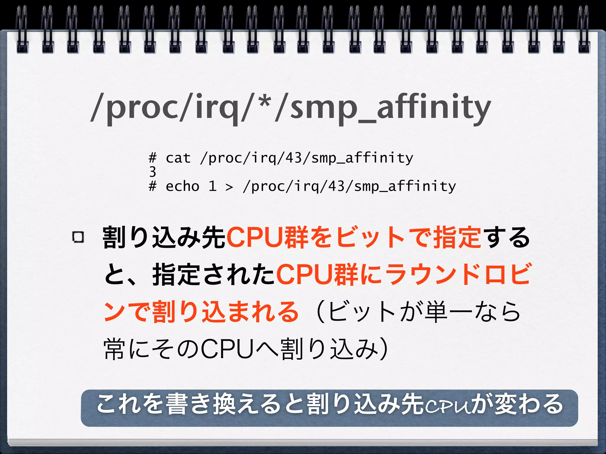
/proc/irq/<irq>/smp_affinity
More Related Content
PDF
PDF
PDF
PPTX
Kubernetesでの性能解析 ~なんとなく遅いからの脱却~(Kubernetes Meetup Tokyo #33 発表資料)
PDF
PDF
PDF
PDF
アーキテクチャから理解するPostgreSQLのレプリケーション
What's hot
PDF
実運用して分かったRabbit MQの良いところ・気をつけること #jjug
PPTX
PDF
わかる!metadata.managedFields / Kubernetes Meetup Tokyo 48
PDF
PPTX
PDF
Grafana LokiではじめるKubernetesロギングハンズオン(NTT Tech Conference #4 ハンズオン資料)
PPTX
Kubernetes環境に対する性能試験(Kubernetes Novice Tokyo #2 発表資料)
PDF
エンジニアなら知っておきたい「仮想マシン」のしくみ v1.1 (hbstudy 17)
PDF
PDF
Javaコードが速く実⾏される秘密 - JITコンパイラ⼊⾨(JJUG CCC 2020 Fall講演資料)
PPTX
PDF
ネットワークの自動化・監視の取り組みについて #netopscoding #npstudy
PDF
PPTX
Jenkins x Kubernetesが簡単だと思ったら大変だった話
PDF
PDF
Kubernetesのしくみ やさしく学ぶ 内部構造とアーキテクチャー
PDF
20111015 勉強会 (PCIe / SR-IOV)
PDF
PDF
PDF
分散トレーシング技術について(Open tracingやjaeger)
Similar to Interrupt Affinityについて
PPTX
PDF
/proc/irq/<irq>/smp_affinity
PDF
PDF
PDF
PDF
本当にわかる Spectre と Meltdown
PDF
PDF
PDF
PDF
17th_ACRi_Webinar_Sadasue-san_Slide_20240724
PPTX
2017-11-15 OpenStack最新情報セミナー Lightning Talk OpenStack環境における通信高速化 ~超入門~
PDF
Altera SDK for OpenCL解体新書 : ホストとデバイスの関係
PDF
[CB19] Semzhu-Project – 手で作る組込み向けハイパーバイザと攻撃検知手法の新しい世界 by 朱義文
PDF
0章 Linuxカーネルを読む前に最低限知っておくべきこと
PDF
Ifcq o smeetup20190517_tokyo_8esp32iot
PDF
PDF
PDF
PDF
PPTX
More from Takuya ASADA
PPTX
Seastar in 歌舞伎座.tech#8「C++初心者会」
PPTX
Seastar:高スループットなサーバアプリケーションの為の新しいフレームワーク
PDF
高スループットなサーバアプリケーションの為の新しいフレームワーク
「Seastar」
PDF
PDF
PDF
OSvのご紹介 in
Java 8 HotSpot meeting
PDF
PDF
OSvのご紹介 in OSC2014 Tokyo/Fall
PDF
PDF
PDF
PDF
Presentation on your terminal
PDF
PDF
PDF
BHyVeでOSvを起動したい
〜BIOSがなくてもこの先生きのこるには〜
PDF
PDF
PDF
Implements BIOS emulation support for BHyVe: A BSD Hypervisor
PDF
PDF
Recently uploaded
PDF
PCCC25(設立25年記念PCクラスタシンポジウム):東京大学情報基盤センター テーマ1/2/3「Society5.0の実現を目指す『計算・データ・学習...
PDF
第25回FA設備技術勉強会_自宅で勉強するROS・フィジカルAIアイテム.pdf
PDF
安価な ロジック・アナライザを アナライズ(?),Analyze report of some cheap logic analyzers
PPTX
PDF
基礎から学ぶ PostgreSQL の性能監視 (PostgreSQL Conference Japan 2025 発表資料)
PDF
visionOS TC「新しいマイホームで過ごすApple Vision Proとの新生活」
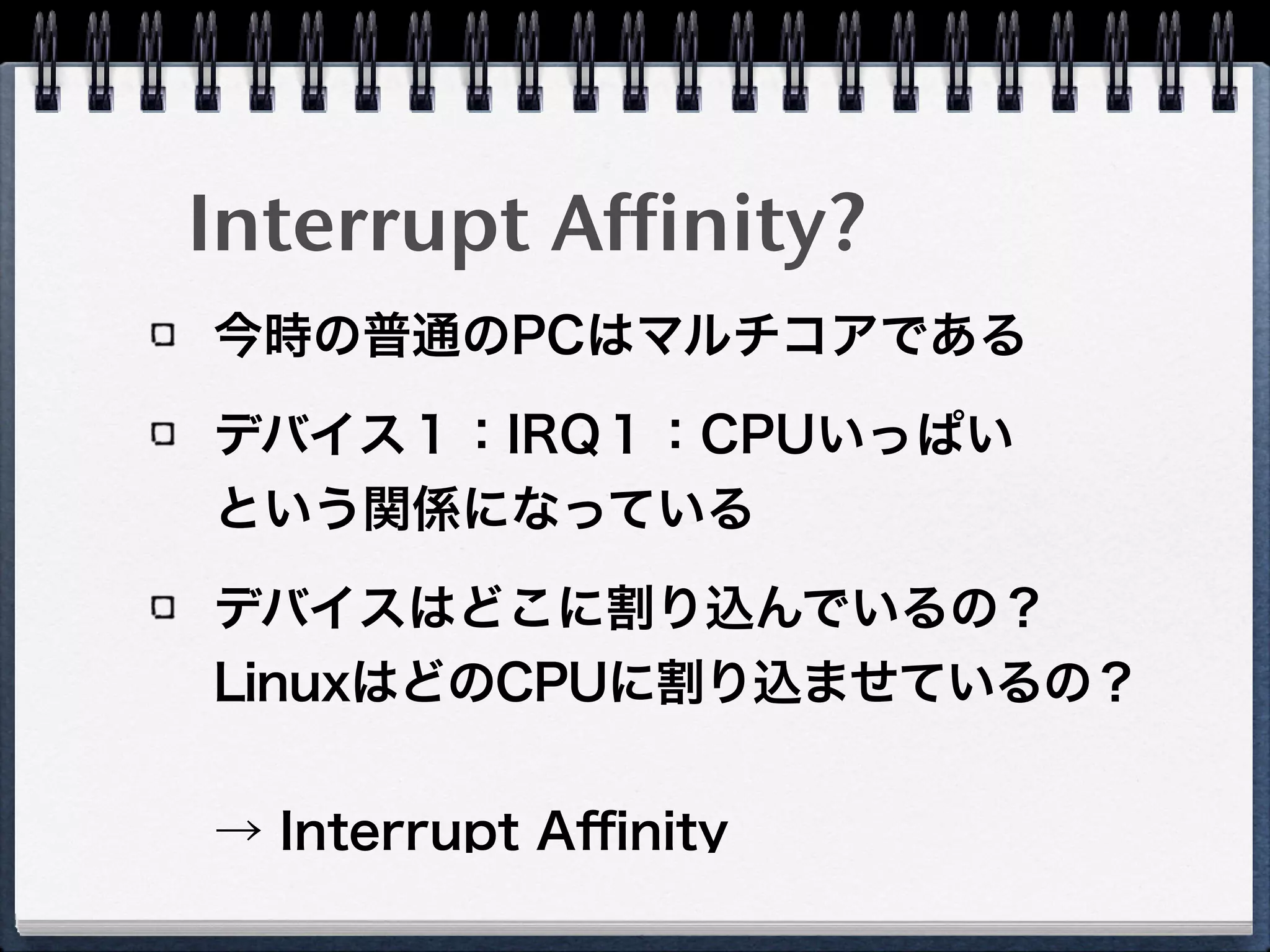
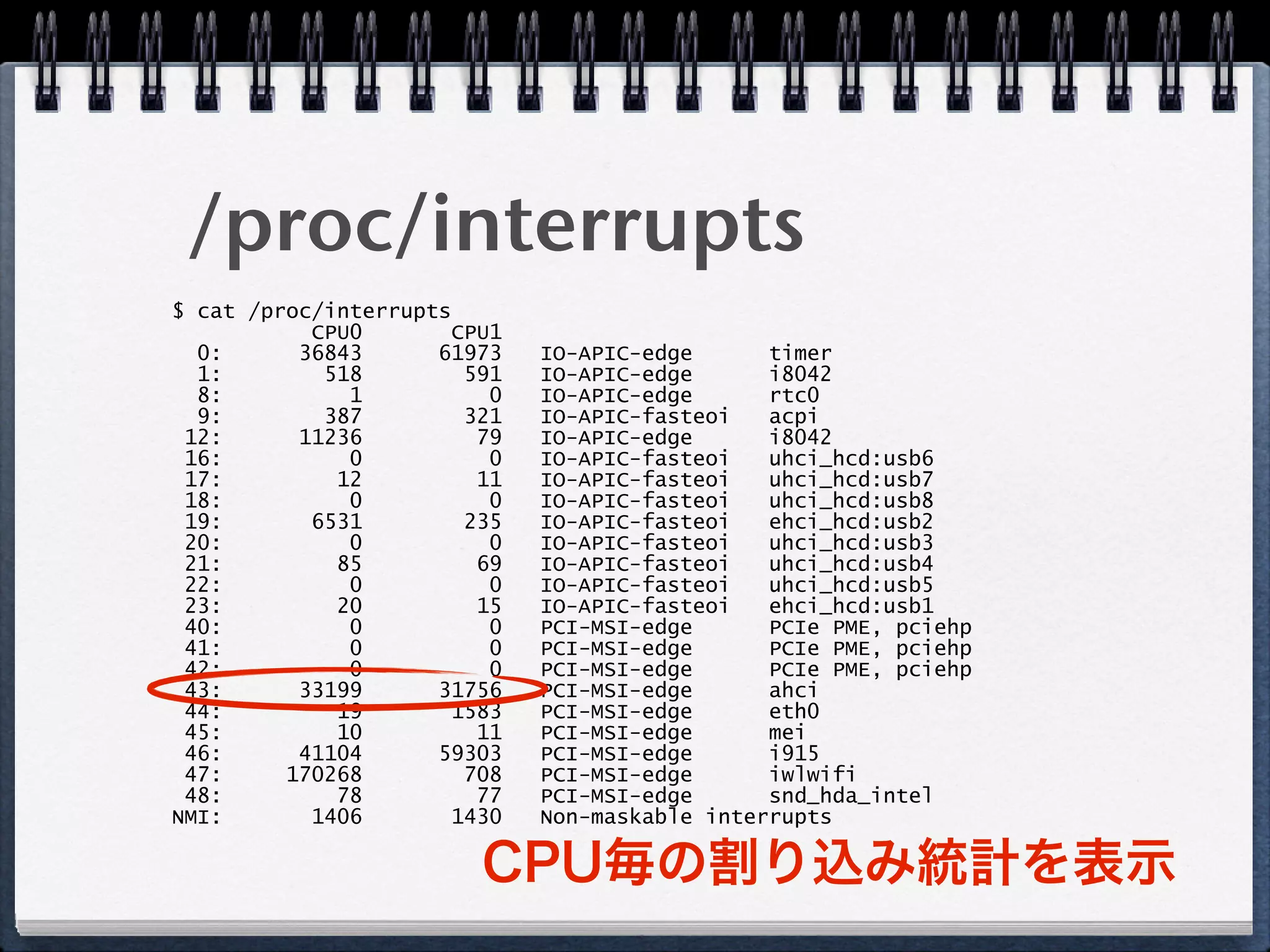
Interrupt Affinityについて 1. 2. 3. 4. $ cat /proc/interrupts
CPU0 CPU1
0: 36843 61973 IO-APIC-edge timer
1: 518 591 IO-APIC-edge i8042
8: 1 0 IO-APIC-edge rtc0
9: 387 321 IO-APIC-fasteoi acpi
12: 11236 79 IO-APIC-edge i8042
16: 0 0 IO-APIC-fasteoi uhci_hcd:usb6
17: 12 11 IO-APIC-fasteoi uhci_hcd:usb7
18: 0 0 IO-APIC-fasteoi uhci_hcd:usb8
19: 6531 235 IO-APIC-fasteoi ehci_hcd:usb2
20: 0 0 IO-APIC-fasteoi uhci_hcd:usb3
21: 85 69 IO-APIC-fasteoi uhci_hcd:usb4
22: 0 0 IO-APIC-fasteoi uhci_hcd:usb5
23: 20 15 IO-APIC-fasteoi ehci_hcd:usb1
40: 0 0 PCI-MSI-edge PCIe PME, pciehp
41: 0 0 PCI-MSI-edge PCIe PME, pciehp
42: 0 0 PCI-MSI-edge PCIe PME, pciehp
43: 33199 31756 PCI-MSI-edge ahci
44: 19 1583 PCI-MSI-edge eth0
45: 10 11 PCI-MSI-edge mei
46: 41104 59303 PCI-MSI-edge i915
47: 170268 708 PCI-MSI-edge iwlwifi
48: 78 77 PCI-MSI-edge snd_hda_intel
NMI: 1406 1430 Non-maskable interrupts
CPU毎の割り込み統計を表示
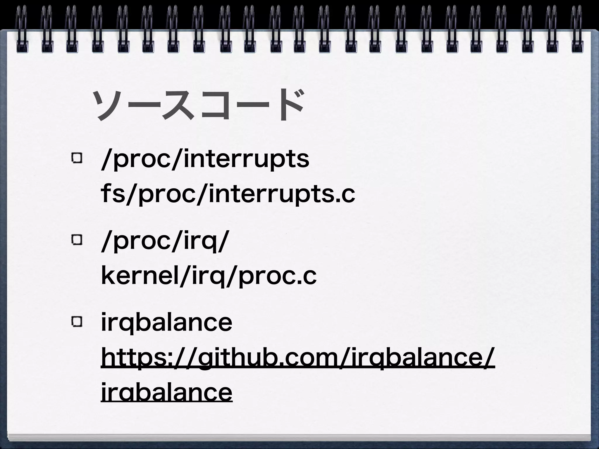
/proc/interrupts
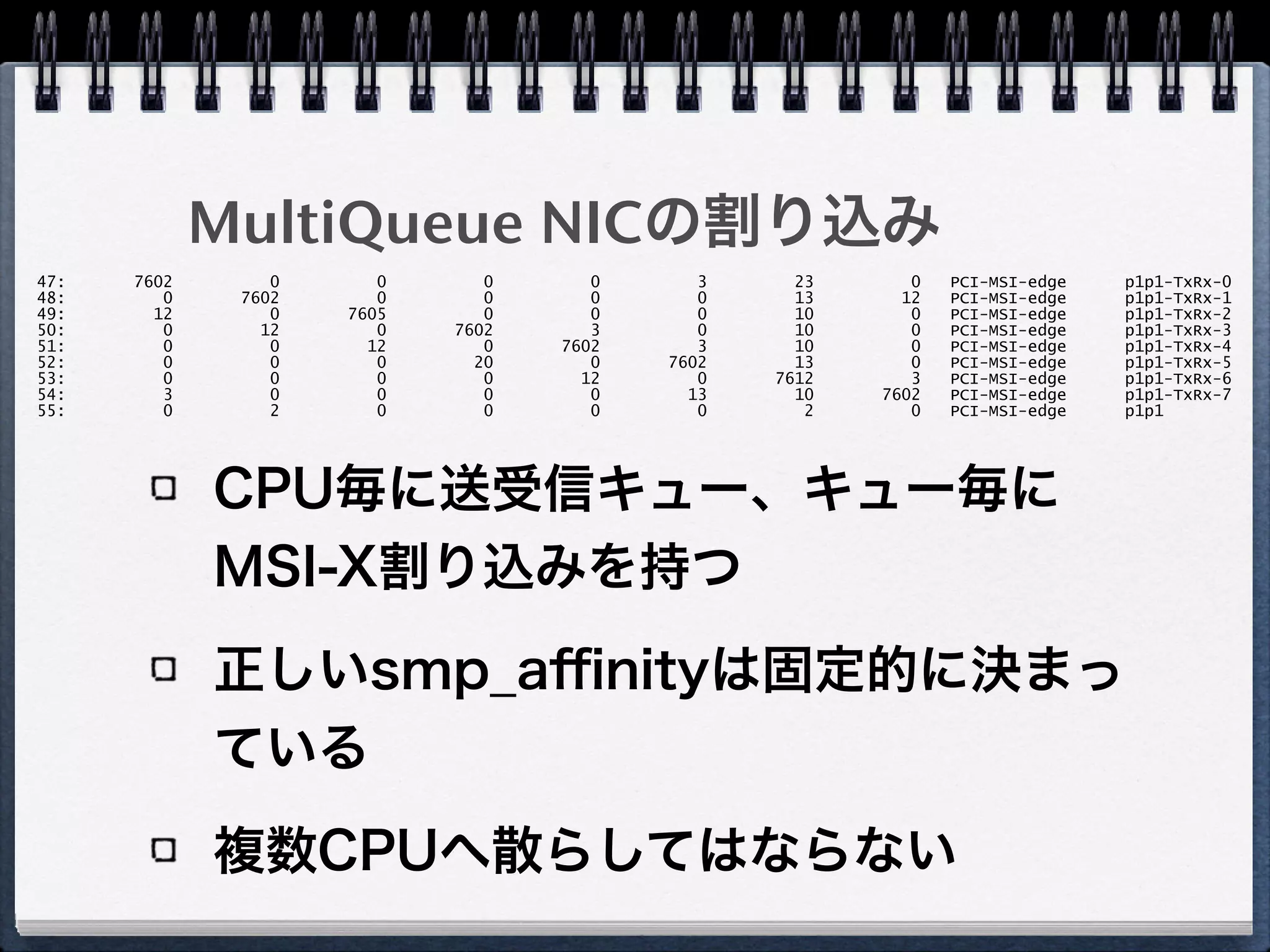
5. 6. 7. 8. 9. 10. MultiQueue NICの割り込み
CPU毎に送受信キュー、キュー毎に
MSI-X割り込みを持つ
正しいsmp_affinityは固定的に決まっ
ている
複数CPUへ散らしてはならない
47: 7602 0 0 0 0 3 23 0 PCI-MSI-edge p1p1-TxRx-0
48: 0 7602 0 0 0 0 13 12 PCI-MSI-edge p1p1-TxRx-1
49: 12 0 7605 0 0 0 10 0 PCI-MSI-edge p1p1-TxRx-2
50: 0 12 0 7602 3 0 10 0 PCI-MSI-edge p1p1-TxRx-3
51: 0 0 12 0 7602 3 10 0 PCI-MSI-edge p1p1-TxRx-4
52: 0 0 0 20 0 7602 13 0 PCI-MSI-edge p1p1-TxRx-5
53: 0 0 0 0 12 0 7612 3 PCI-MSI-edge p1p1-TxRx-6
54: 3 0 0 0 0 13 10 7602 PCI-MSI-edge p1p1-TxRx-7
55: 0 2 0 0 0 0 2 0 PCI-MSI-edge p1p1
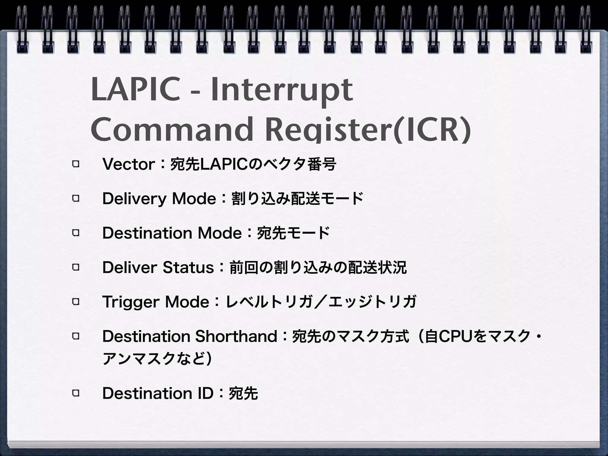
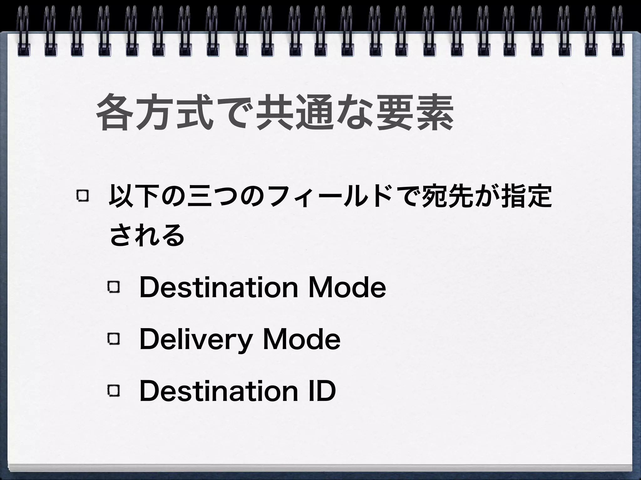
11. 12. 13. 14. 15. LAPIC - Interrupt
Command Register(ICR)
Vector:宛先LAPICのベクタ番号
Delivery Mode:割り込み配送モード
Destination Mode:宛先モード
Deliver Status:前回の割り込みの配送状況
Trigger Mode:レベルトリガ/エッジトリガ
Destination Shorthand:宛先のマスク方式(自CPUをマスク・
アンマスクなど)
Destination ID:宛先
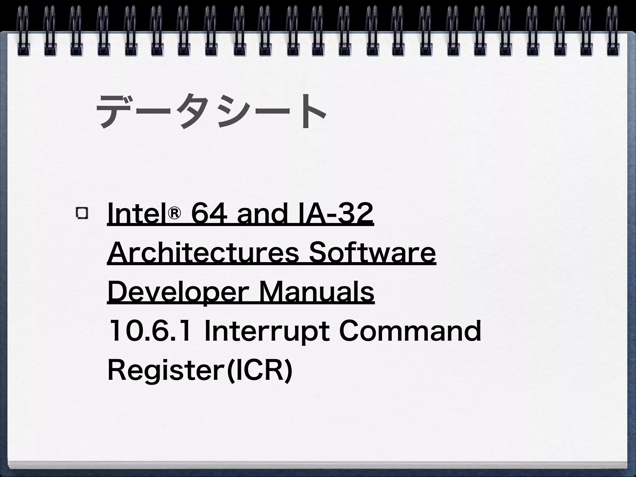
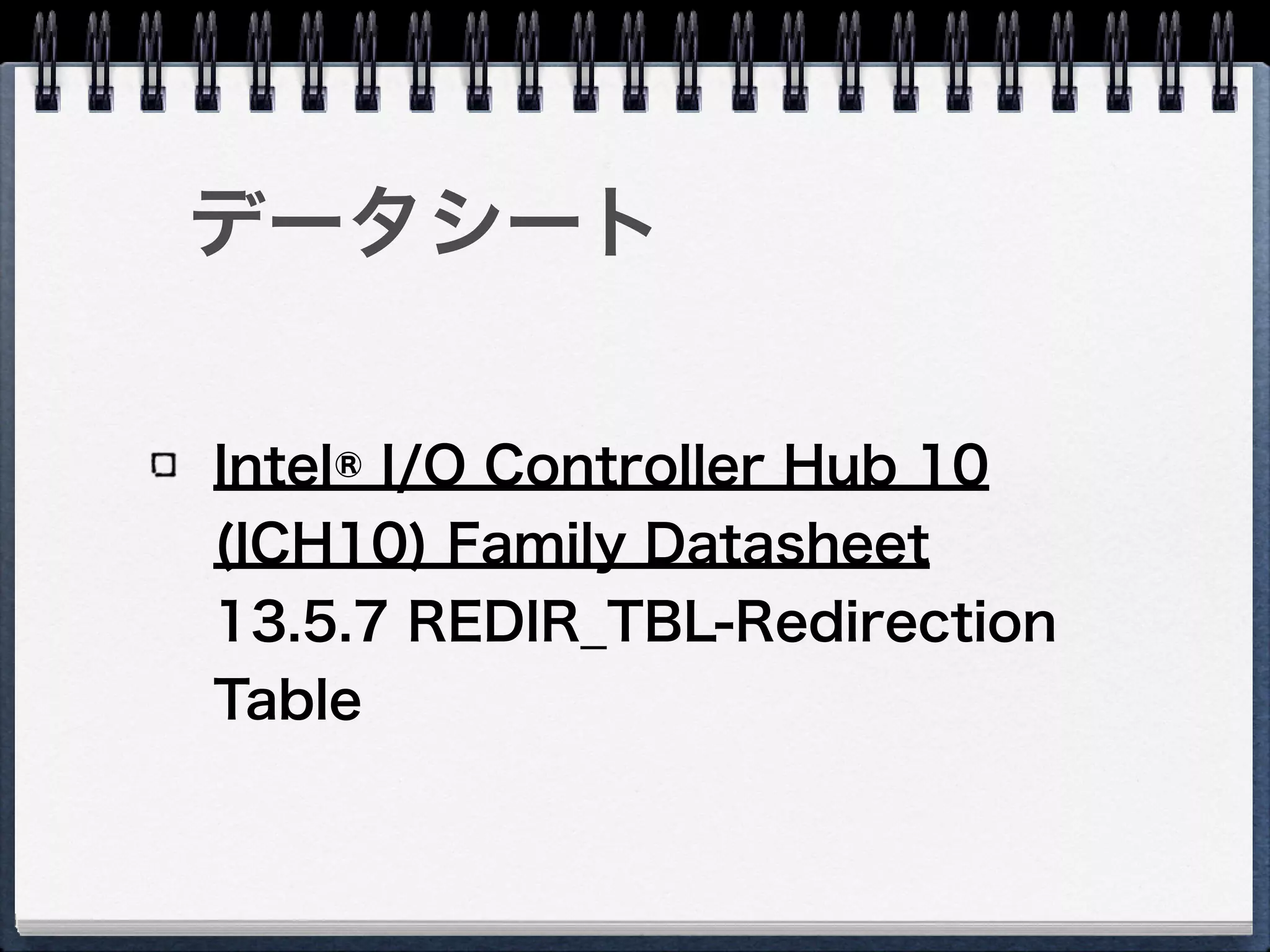
16. 17. データシート
Intel® 64 and IA-32
Architectures Software
Developer Manuals
10.6.1 Interrupt Command
Register(ICR)
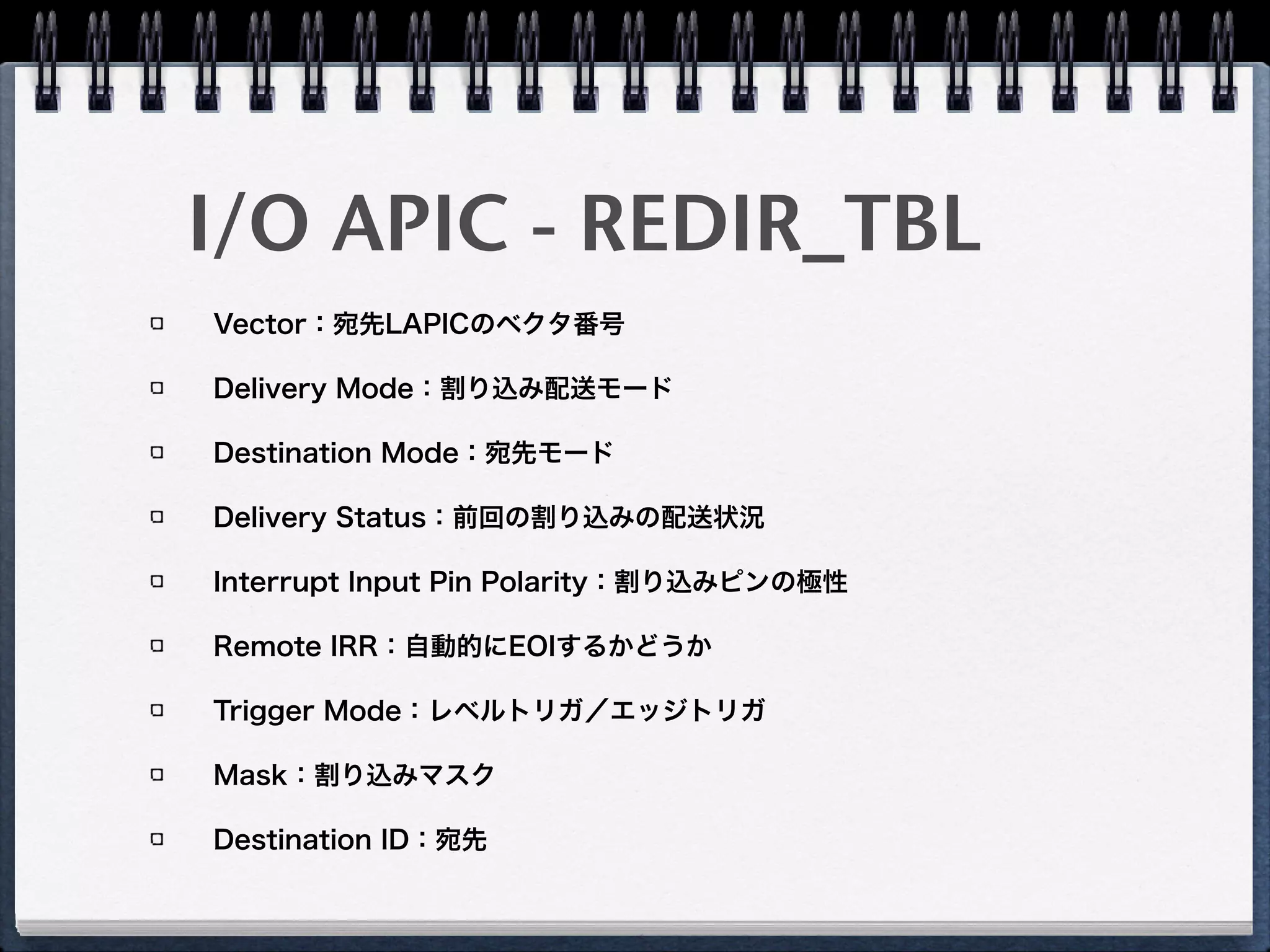
18. 19. 20. 21. I/O APIC - REDIR_TBL
Vector:宛先LAPICのベクタ番号
Delivery Mode:割り込み配送モード
Destination Mode:宛先モード
Delivery Status:前回の割り込みの配送状況
Interrupt Input Pin Polarity:割り込みピンの極性
Remote IRR:自動的にEOIするかどうか
Trigger Mode:レベルトリガ/エッジトリガ
Mask:割り込みマスク
Destination ID:宛先
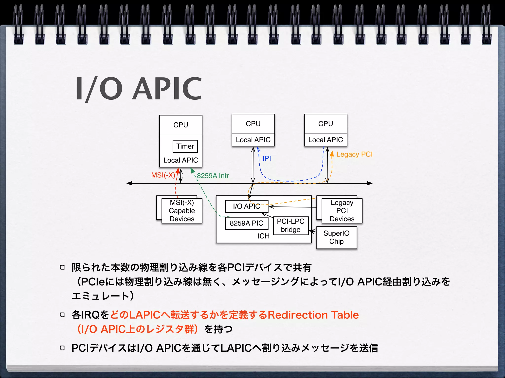
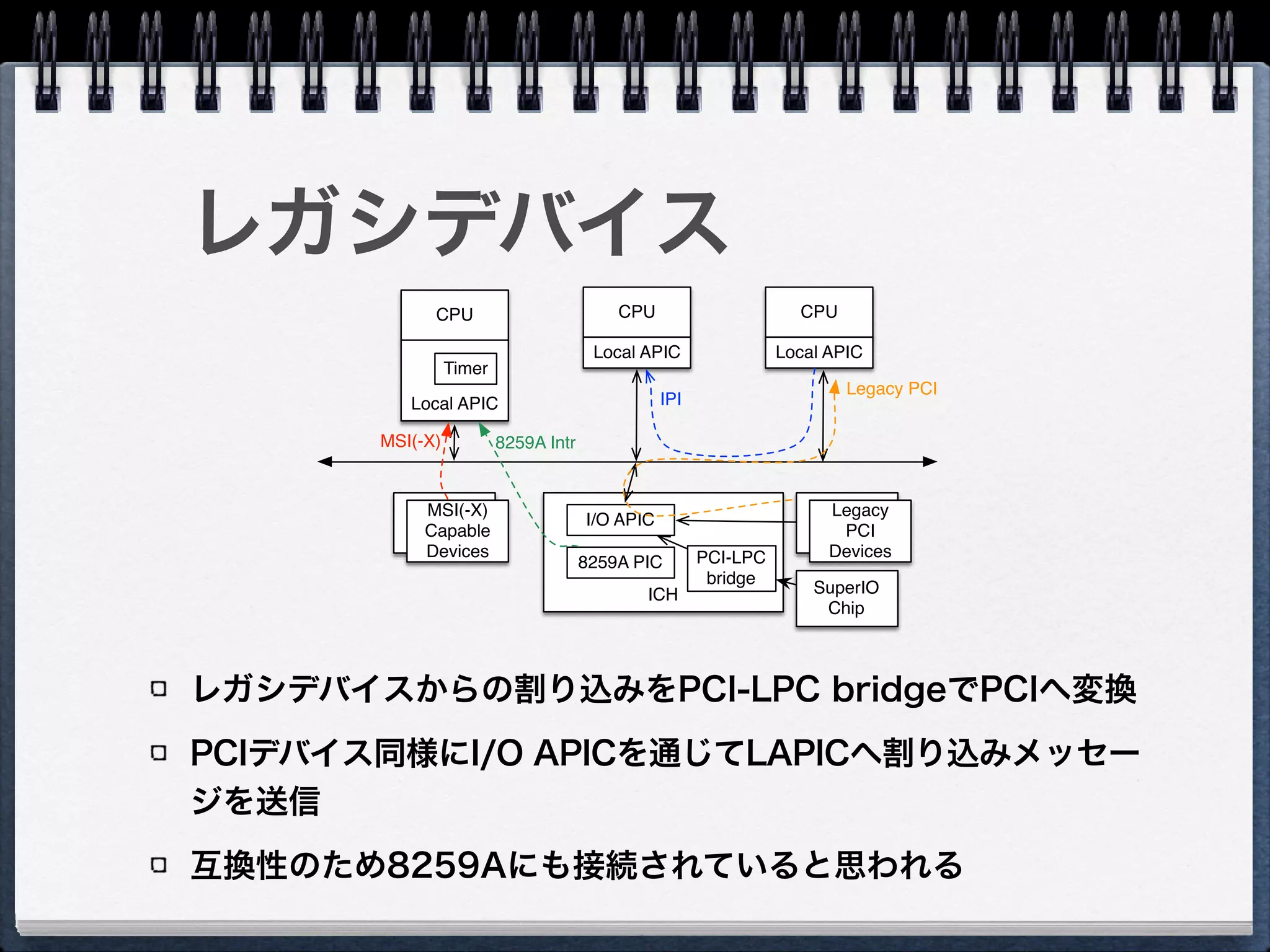
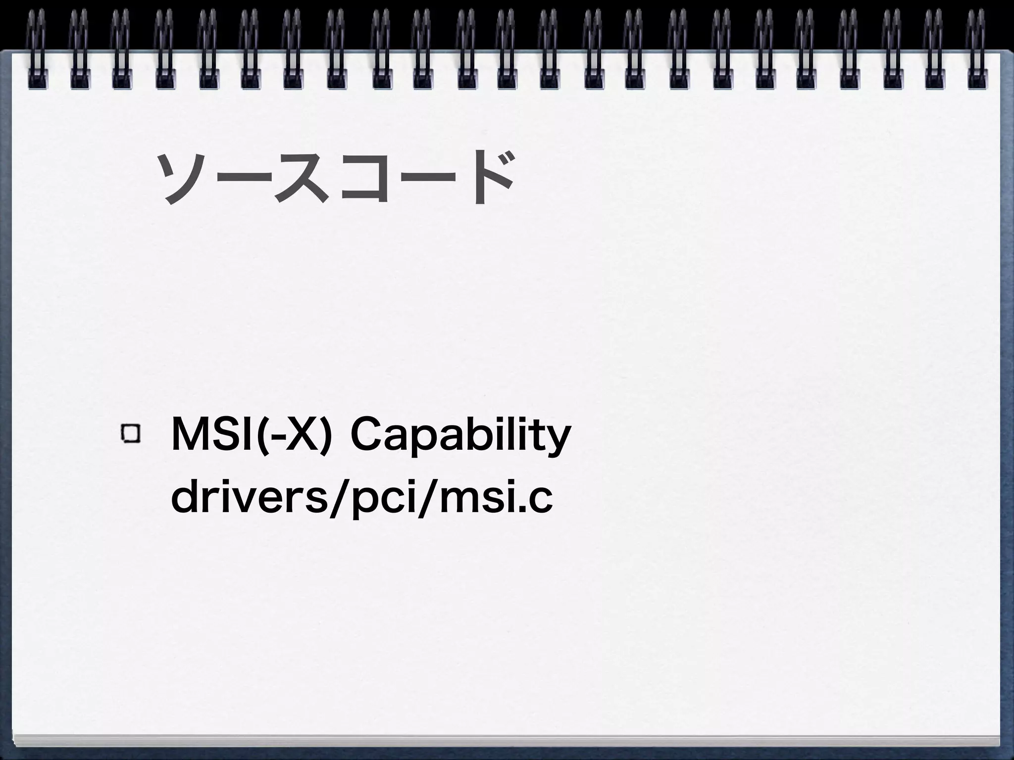
22. 23. 24. 25. 26. MSI(-X) capable PCI devices
各デバイスが任意の数のIRQを持てる
各IRQの割り込み先LAPICはPCIデバイスのPCI
Configuration Spaceに持つ
PCIデバイスは直接LAPICへ割り込みメッセージを送信
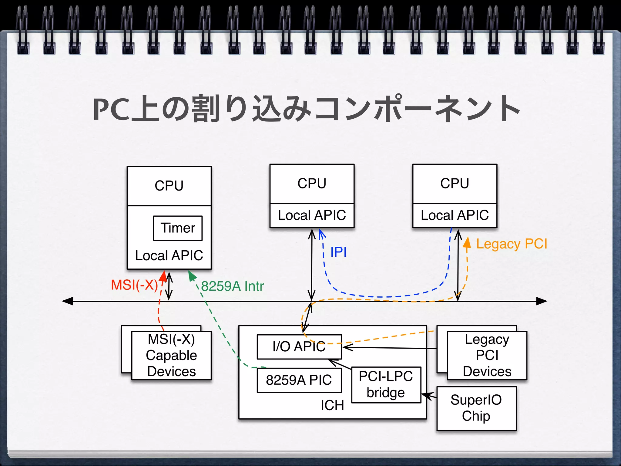
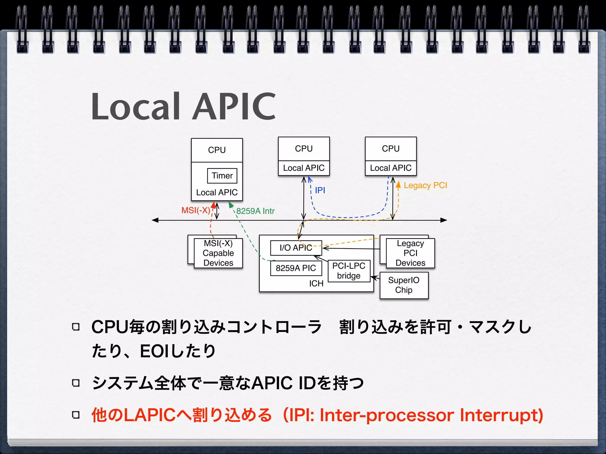
CPU
Local APIC
CPU
Local APIC
CPU
Local APIC
ICH
8259A PIC
Timer
I/O APIC
Legacy
PCI
Devices
MSI(-X)
Capable
Devices
IPI
Legacy PCI
8259A IntrMSI(-X)
PCI-LPC
bridge
SuperIO
Chip
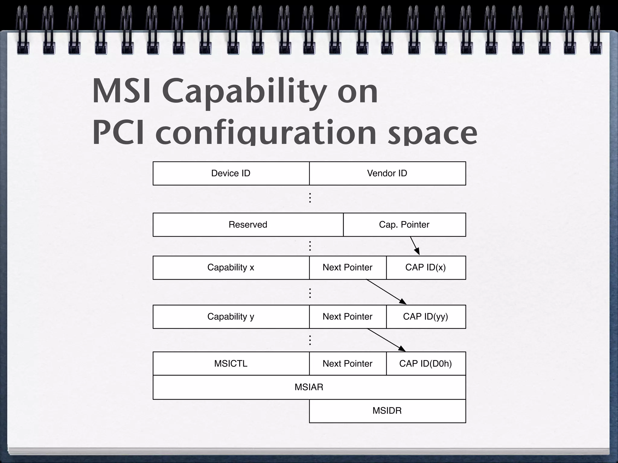
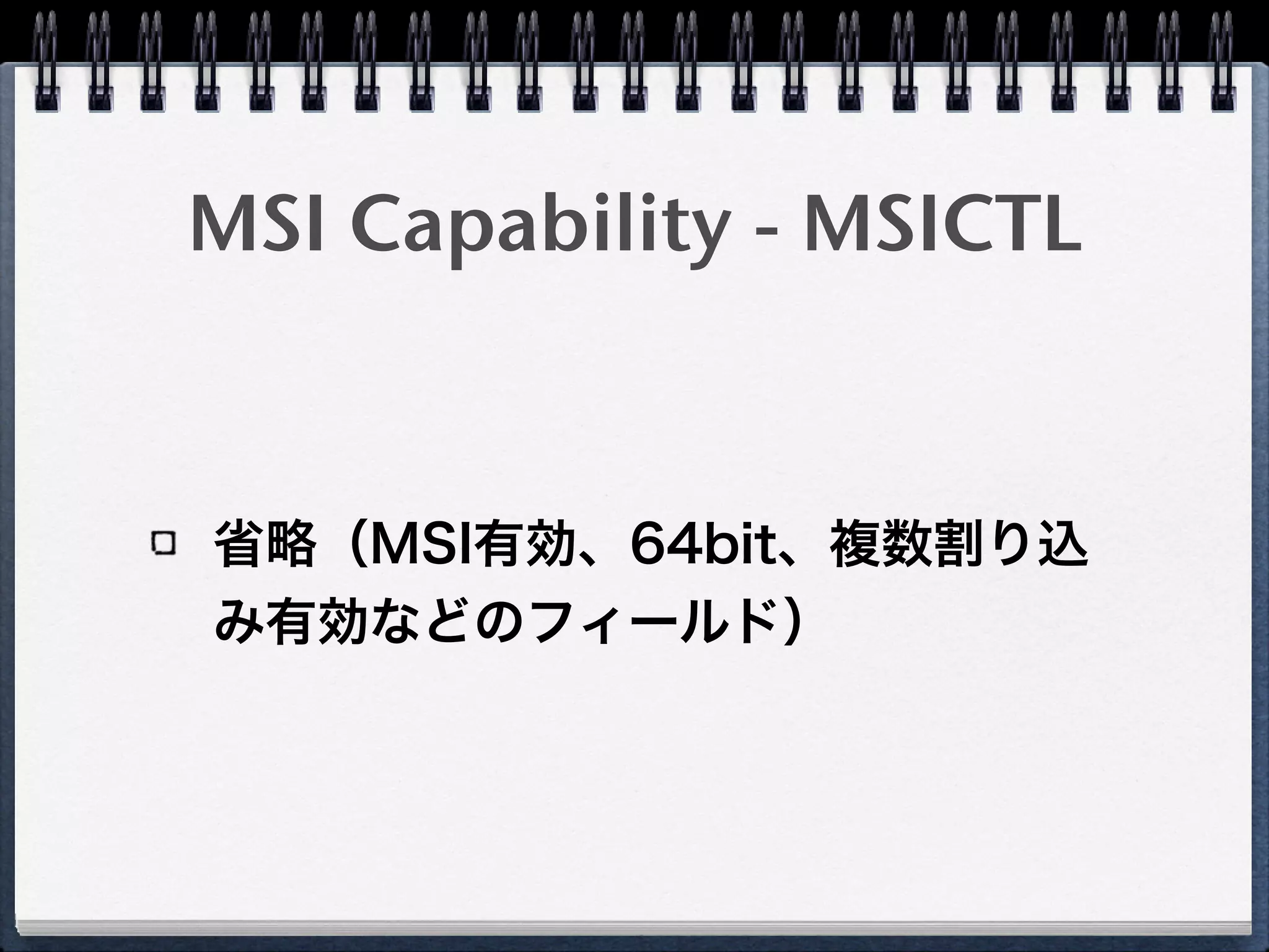
27. MSI Capability on
PCI configuration space
Device ID Vendor ID
…
Reserved Cap. Pointer
…
Capability x CAP ID(x)Next Pointer
…
Capability y CAP ID(yy)Next Pointer
…
MSICTL CAP ID(D0h)Next Pointer
MSIAR
MSIDR
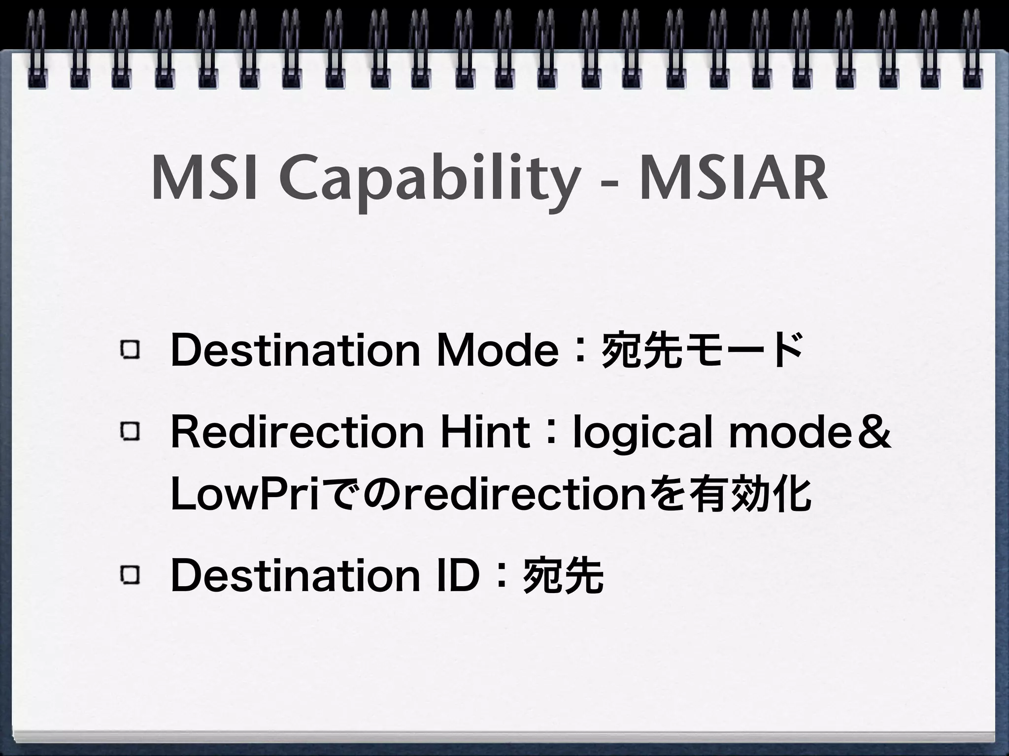
28. 29. MSI Capability - MSIAR
Destination Mode:宛先モード
Redirection Hint:logical mode&
LowPriでのredirectionを有効化
Destination ID:宛先
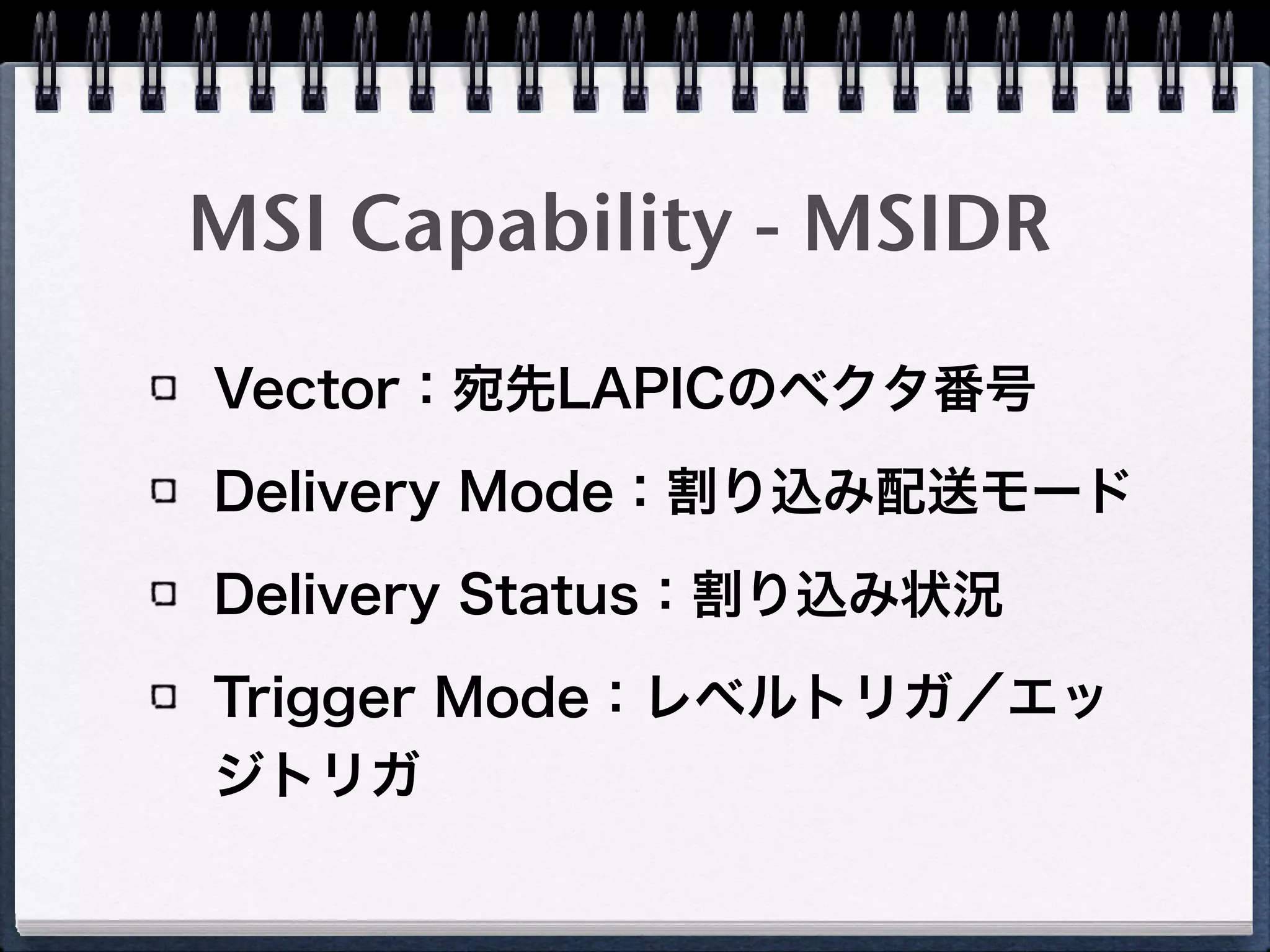
30. MSI Capability - MSIDR
Vector:宛先LAPICのベクタ番号
Delivery Mode:割り込み配送モード
Delivery Status:割り込み状況
Trigger Mode:レベルトリガ/エッ
ジトリガ
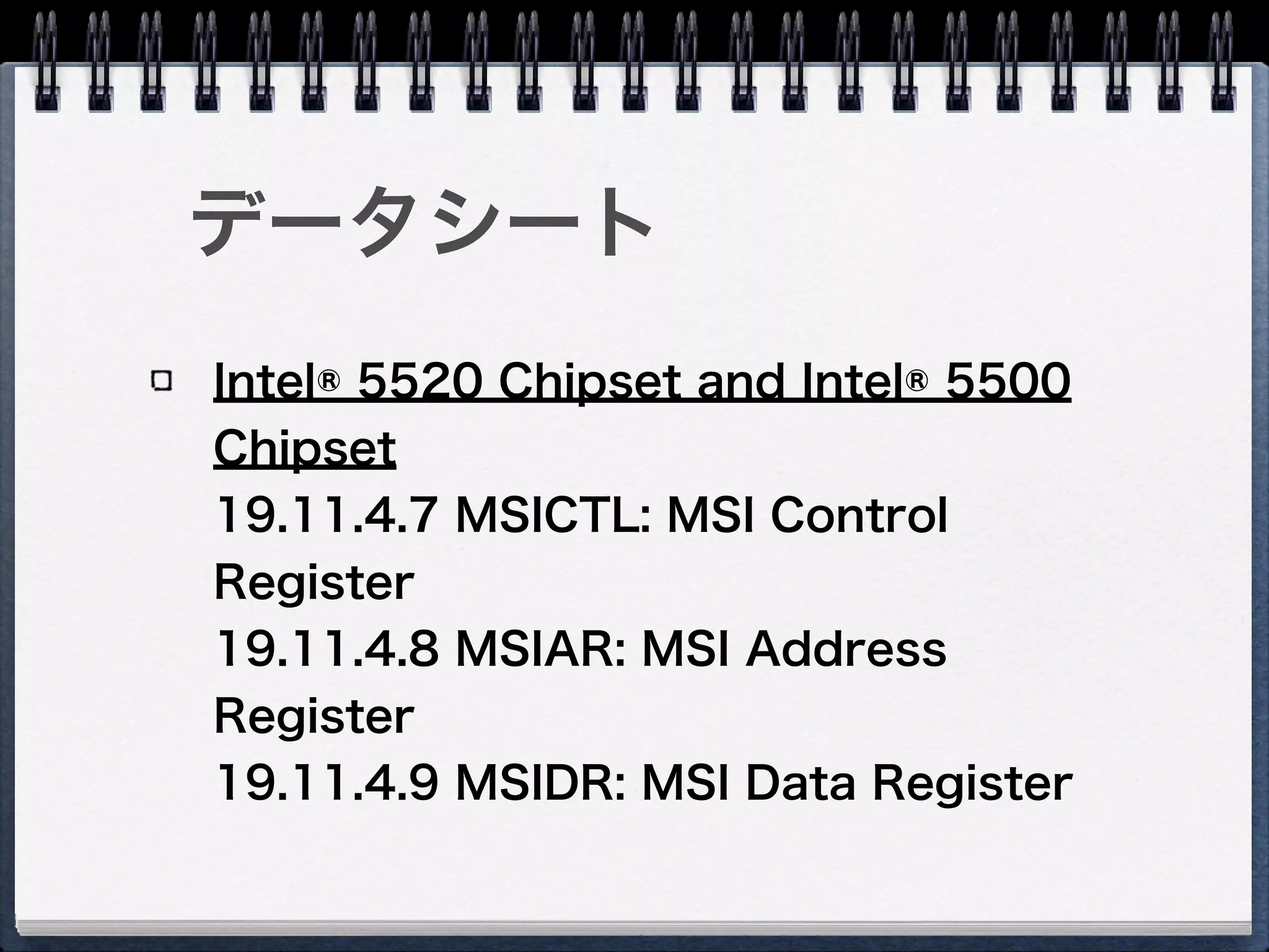
31. 32. 33. データシート
Intel® 5520 Chipset and Intel® 5500
Chipset
19.11.4.7 MSICTL: MSI Control
Register
19.11.4.8 MSIAR: MSI Address
Register
19.11.4.9 MSIDR: MSI Data Register
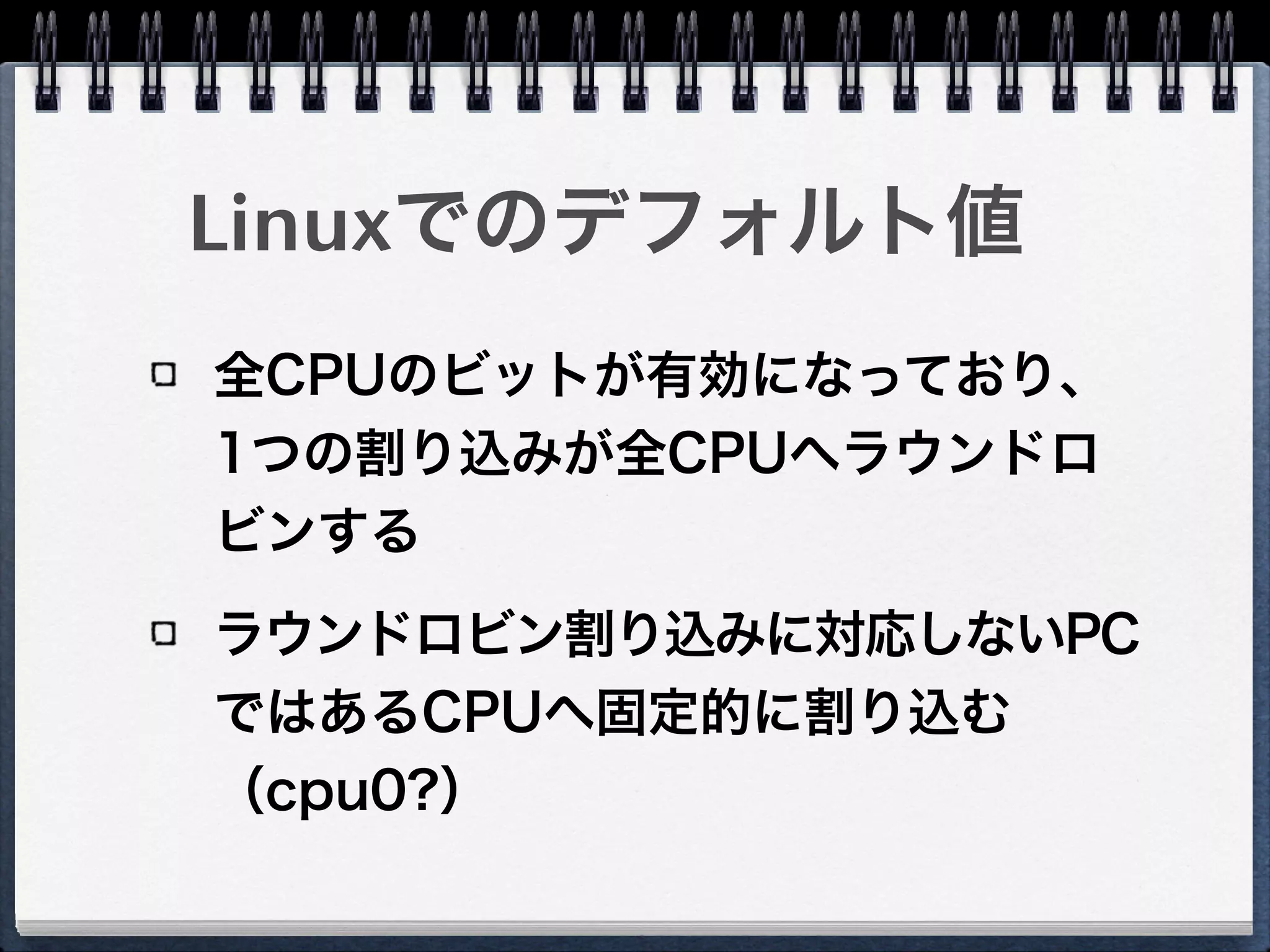
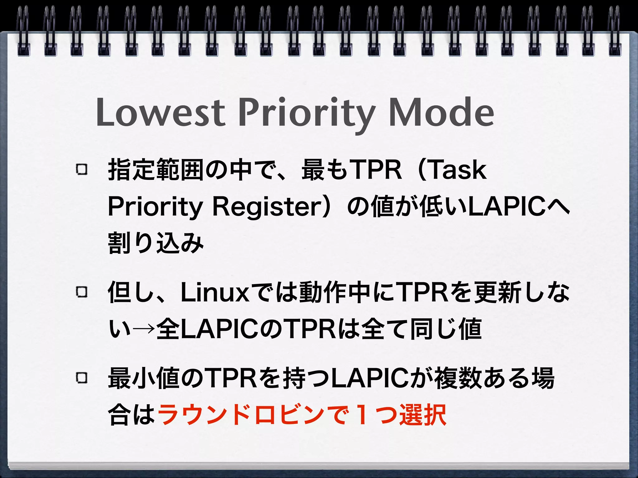
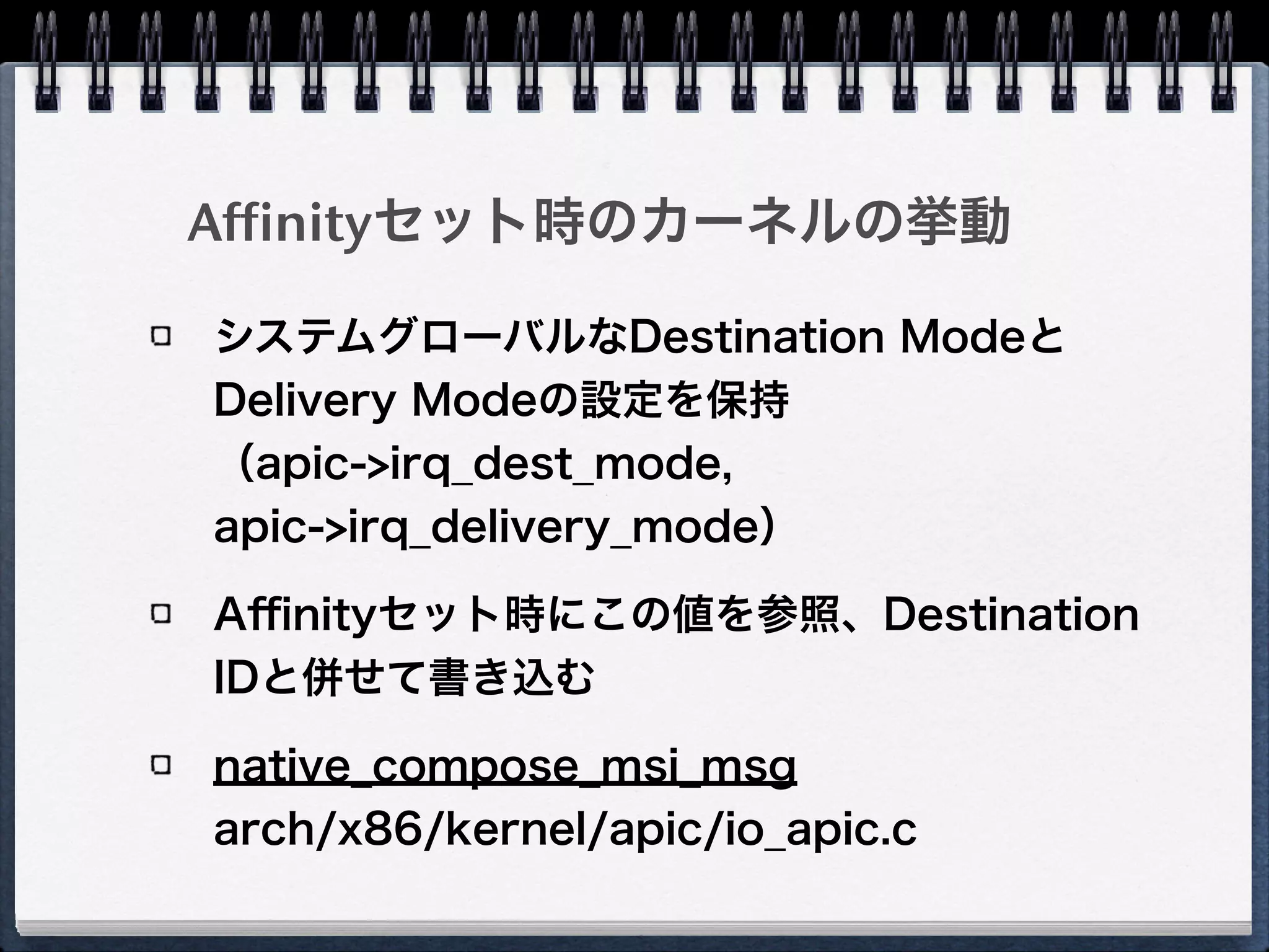
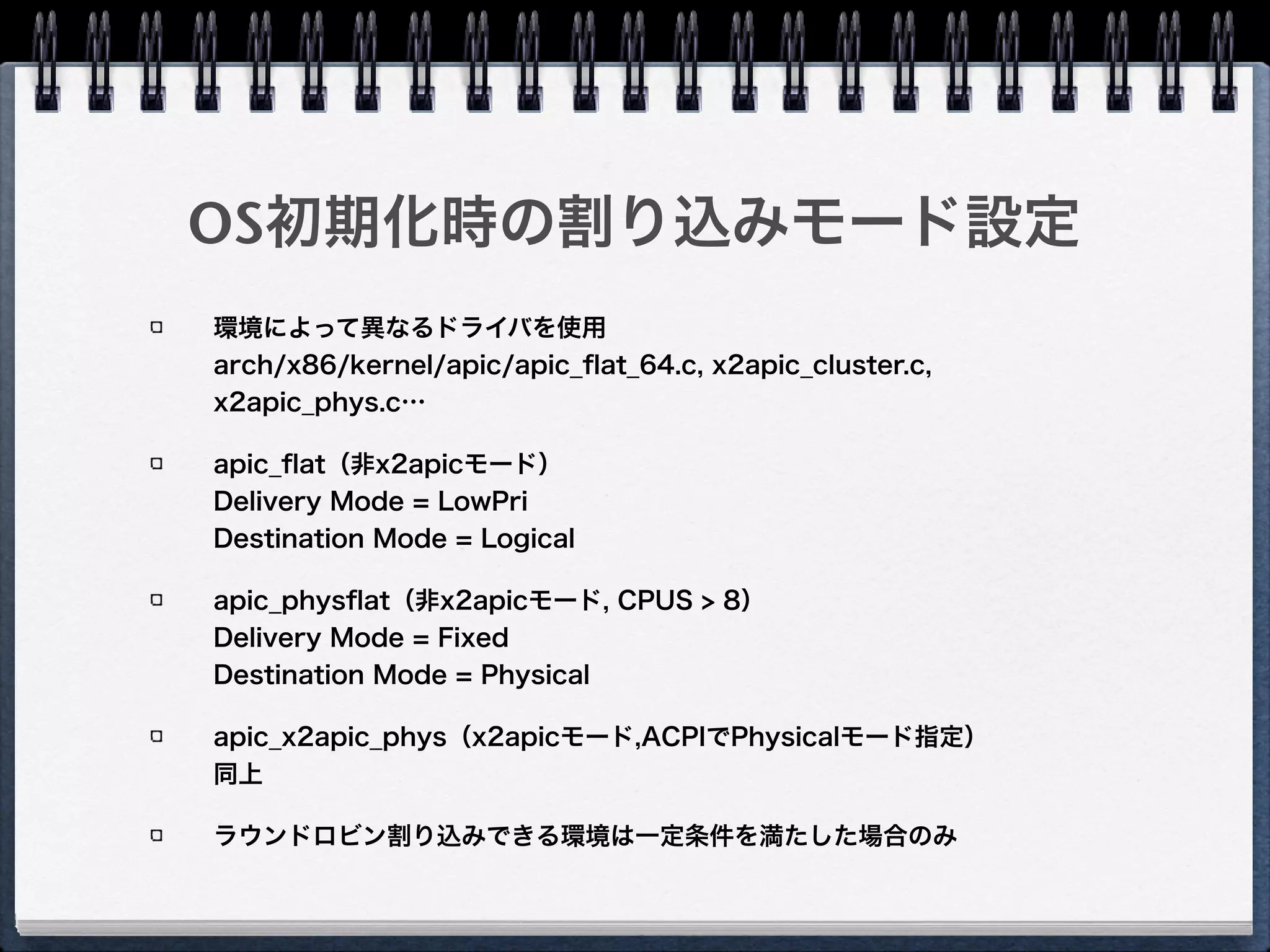
34. 35. 割り込み先の指定方法
Physical Destination Mode
Destination FieldにAPIC IDを指定
「常に同じCPUへ割り込み」を実現
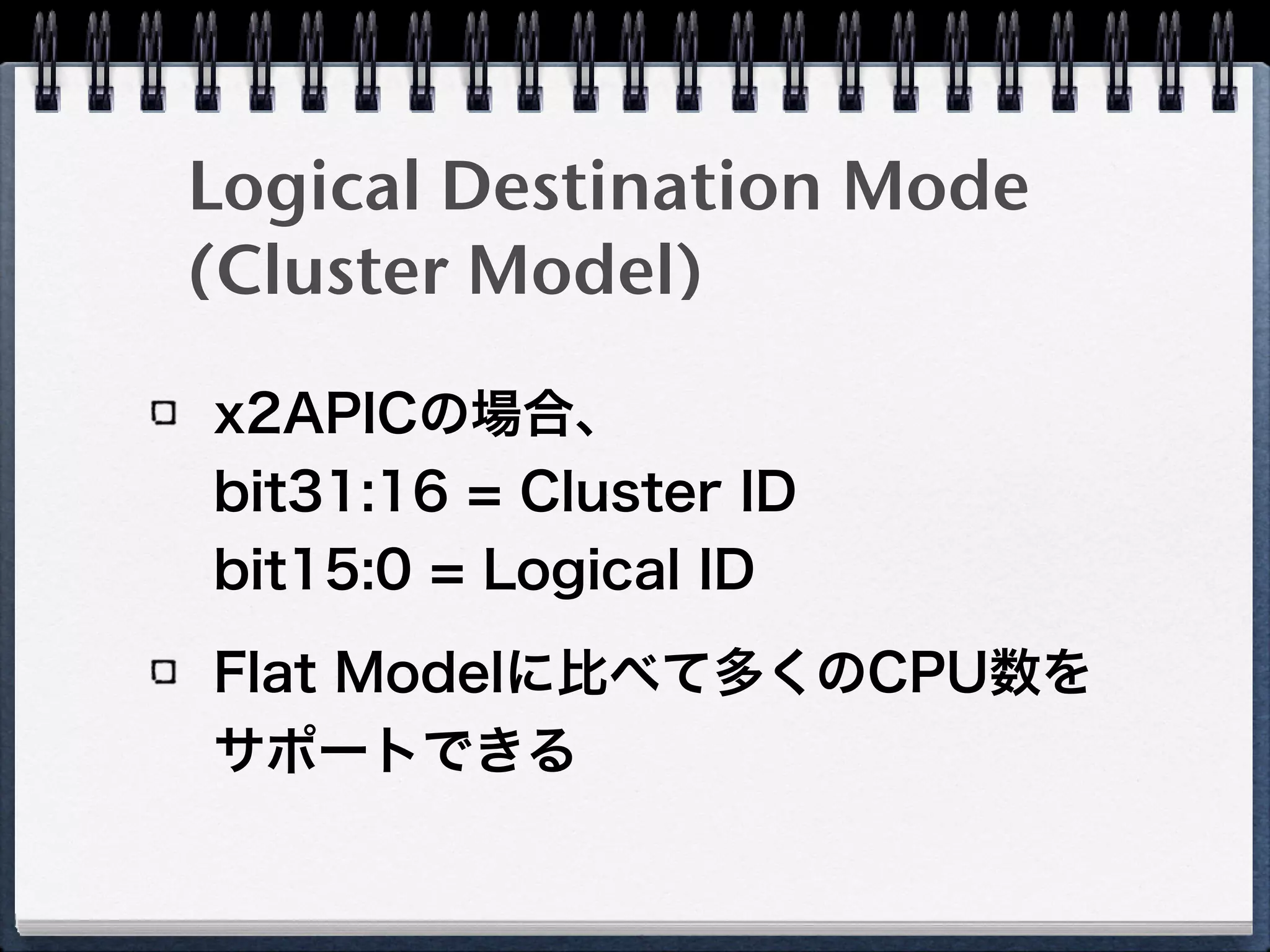
Logical Destination Mode(Flat Model)
Destination Fieldのbitで宛先LAPIC群の範囲を表現
Delivery Mode
Fixed
指定範囲の全てのLAPICへ割り込み
Lowest Priority
指定範囲の中で、最もTPR(Task Priority Register)の値が
低いCPUへ割り込み
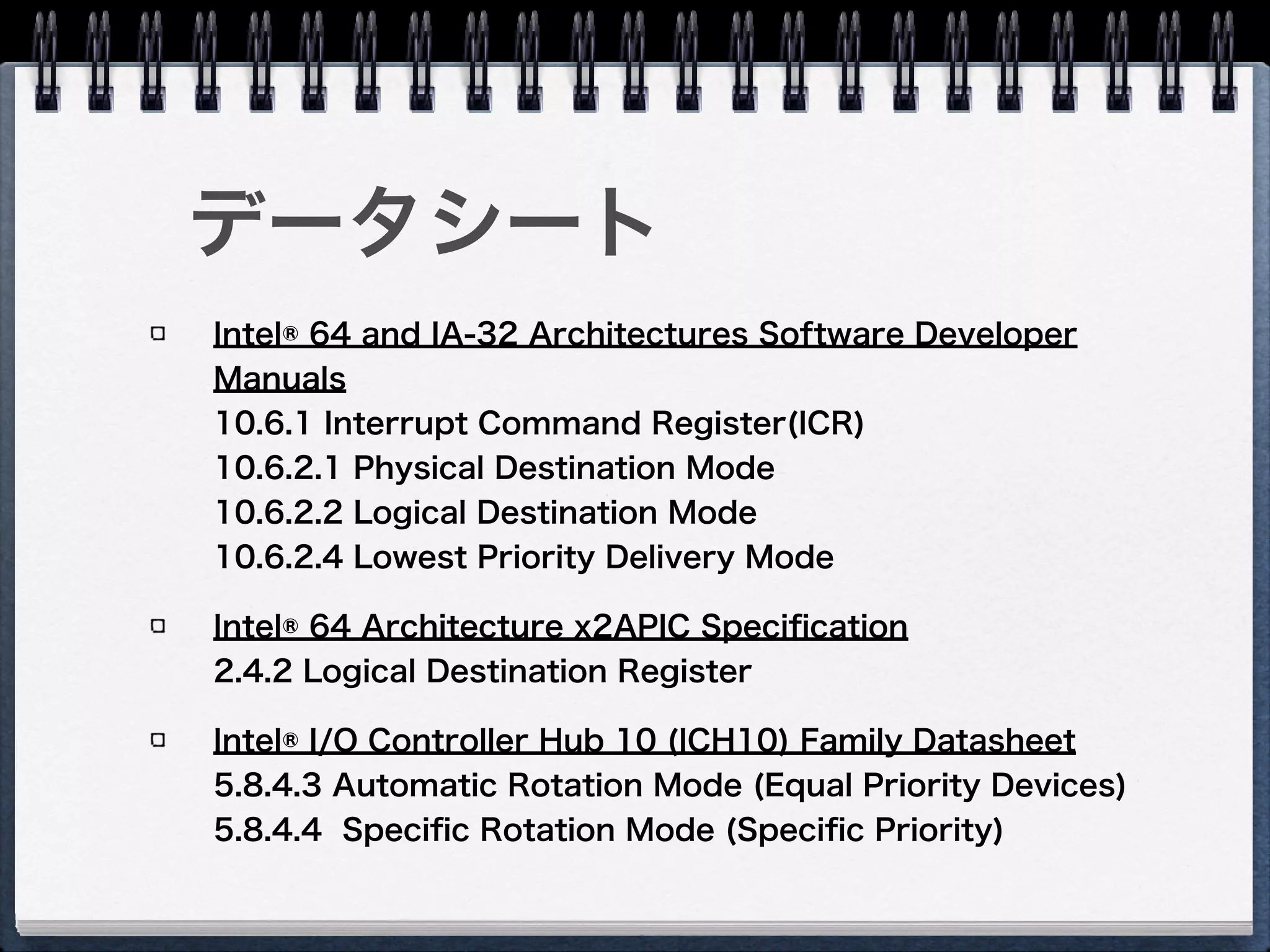
36. 37. 38. データシート
Intel® 64 and IA-32 Architectures Software Developer
Manuals
10.6.1 Interrupt Command Register(ICR)
10.6.2.1 Physical Destination Mode
10.6.2.2 Logical Destination Mode
10.6.2.4 Lowest Priority Delivery Mode
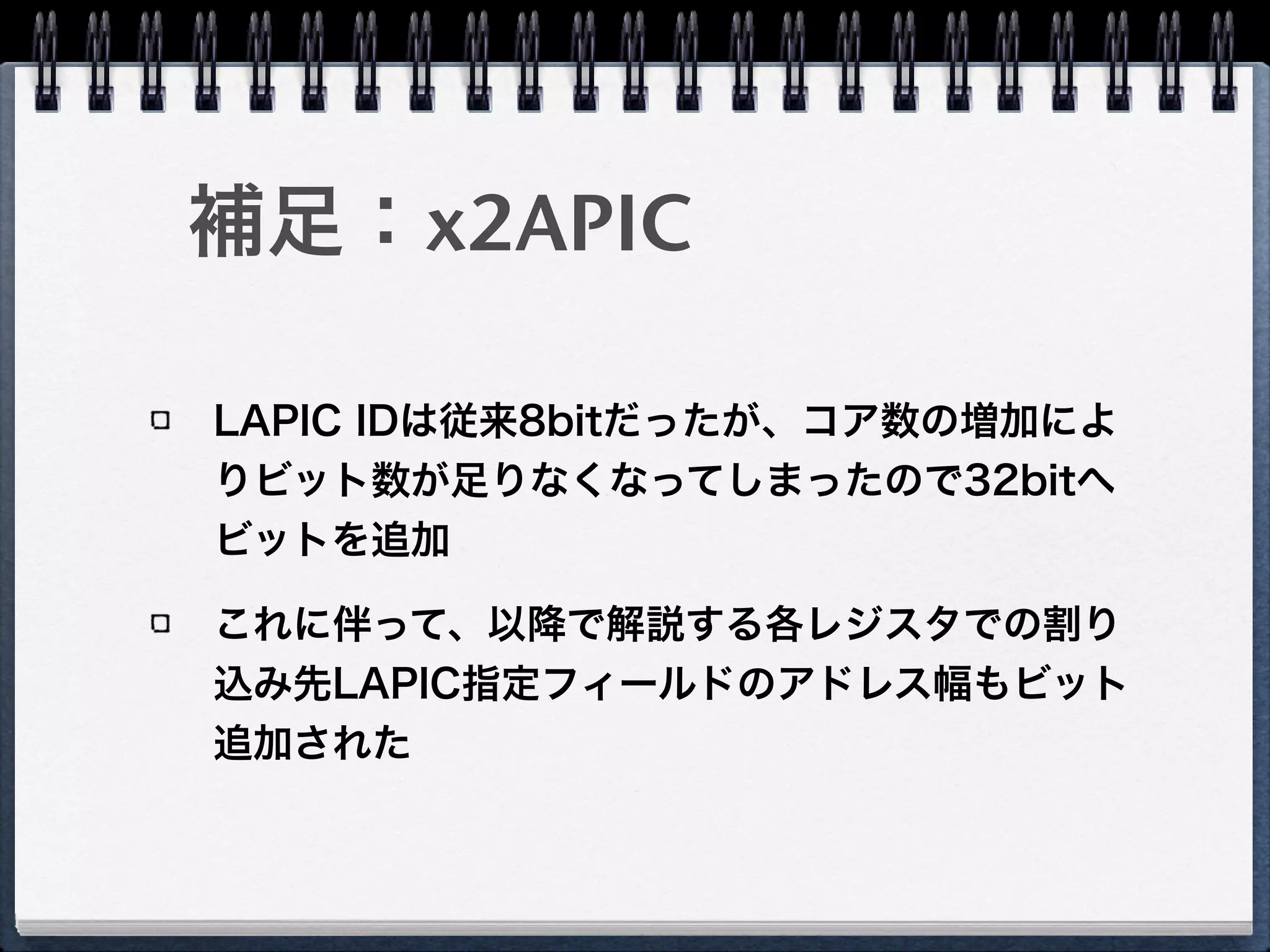
Intel® 64 Architecture x2APIC Specification
2.4.2 Logical Destination Register
Intel® I/O Controller Hub 10 (ICH10) Family Datasheet
5.8.4.3 Automatic Rotation Mode (Equal Priority Devices)
5.8.4.4 Specific Rotation Mode (Specific Priority)
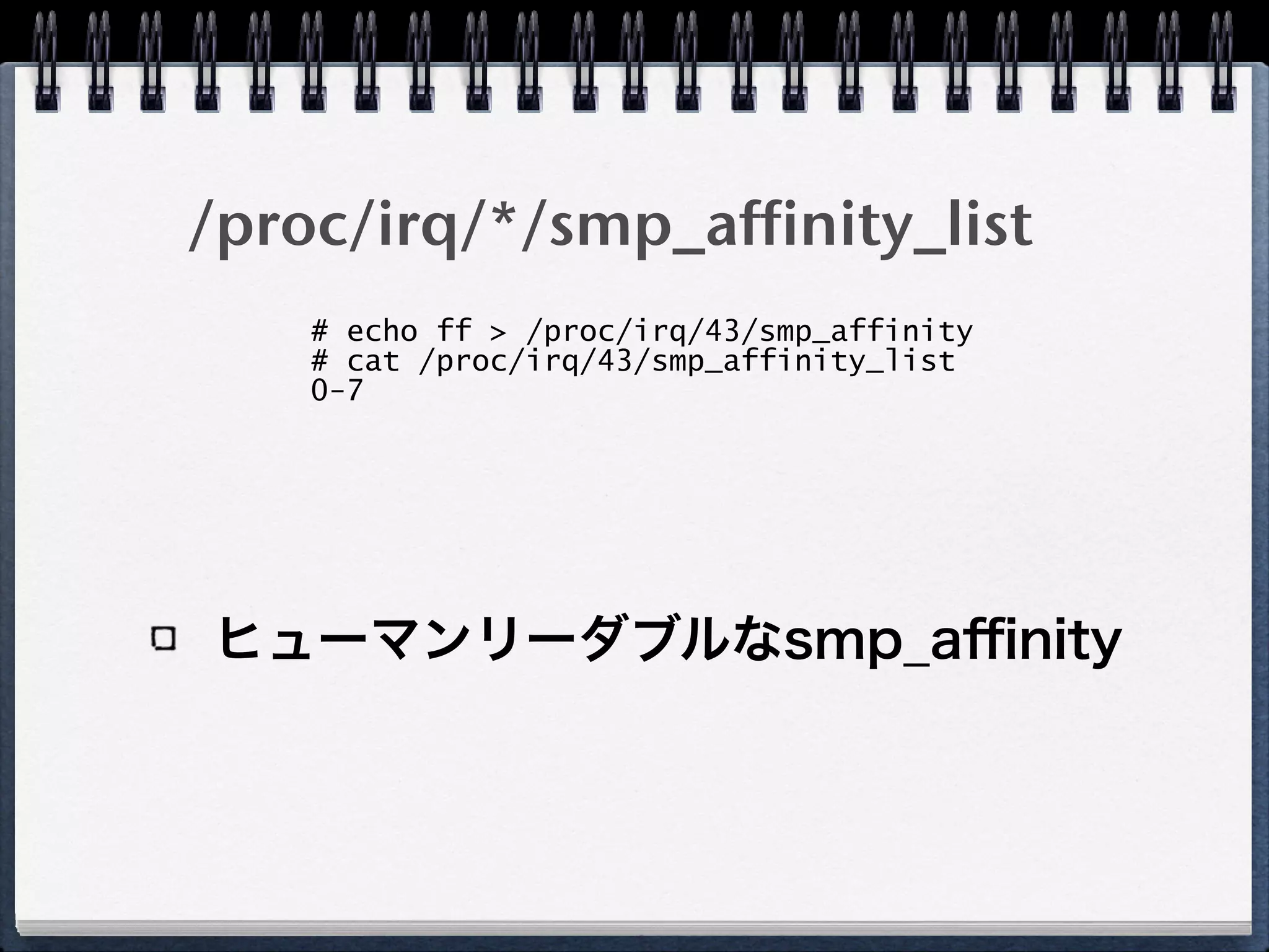
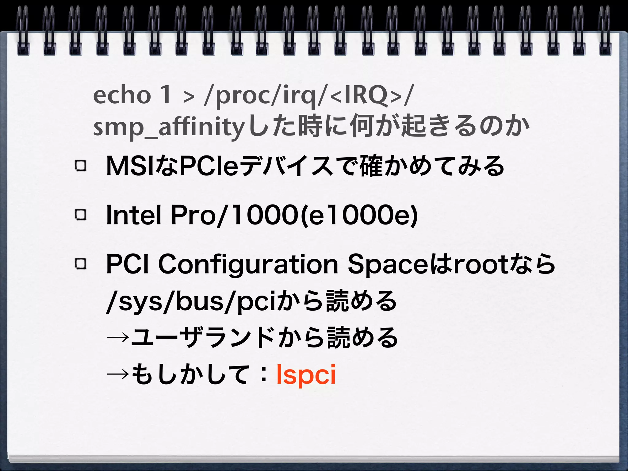
39. echo 1 > /proc/irq/<IRQ>/
smp_affinityした時に何が起きるのか
MSIなPCIeデバイスで確かめてみる
Intel Pro/1000(e1000e)
PCI Configuration Spaceはrootなら
/sys/bus/pciから読める
→ユーザランドから読める
→もしかして:lspci
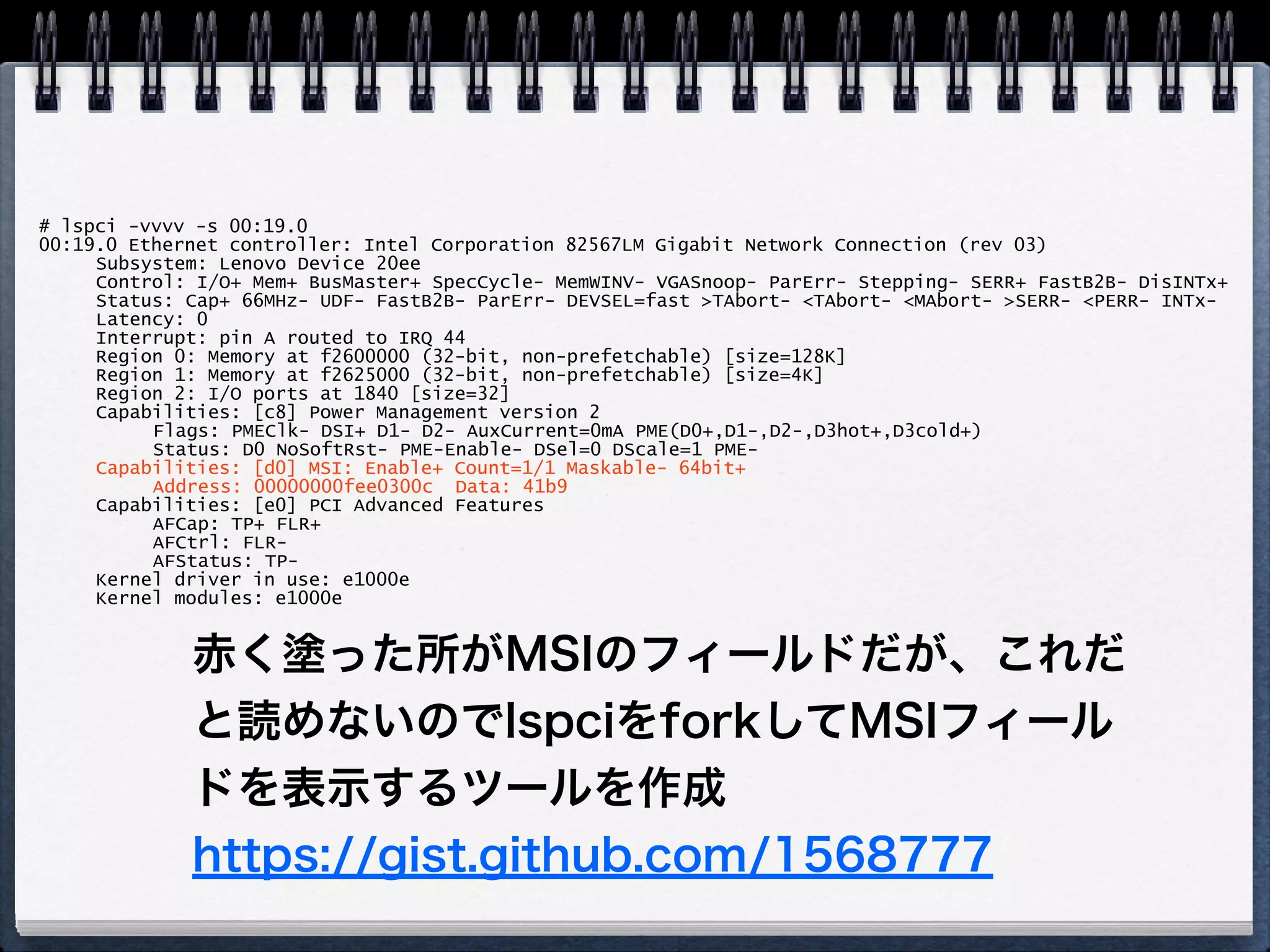
40. # lspci -vvvv -s 00:19.0
00:19.0 Ethernet controller: Intel Corporation 82567LM Gigabit Network Connection (rev 03)
Subsystem: Lenovo Device 20ee
Control: I/O+ Mem+ BusMaster+ SpecCycle- MemWINV- VGASnoop- ParErr- Stepping- SERR+ FastB2B- DisINTx+
Status: Cap+ 66MHz- UDF- FastB2B- ParErr- DEVSEL=fast >TAbort- <TAbort- <MAbort- >SERR- <PERR- INTx-
Latency: 0
Interrupt: pin A routed to IRQ 44
Region 0: Memory at f2600000 (32-bit, non-prefetchable) [size=128K]
Region 1: Memory at f2625000 (32-bit, non-prefetchable) [size=4K]
Region 2: I/O ports at 1840 [size=32]
Capabilities: [c8] Power Management version 2
Flags: PMEClk- DSI+ D1- D2- AuxCurrent=0mA PME(D0+,D1-,D2-,D3hot+,D3cold+)
Status: D0 NoSoftRst- PME-Enable- DSel=0 DScale=1 PME-
Capabilities: [d0] MSI: Enable+ Count=1/1 Maskable- 64bit+
Address: 00000000fee0300c Data: 41b9
Capabilities: [e0] PCI Advanced Features
AFCap: TP+ FLR+
AFCtrl: FLR-
AFStatus: TP-
Kernel driver in use: e1000e
Kernel modules: e1000e
赤く塗った所がMSIのフィールドだが、これだ
と読めないのでlspciをforkしてMSIフィール
ドを表示するツールを作成
https://gist.github.com/1568777
41. # gcc -lpci msireg.c!
# ./a.out 00:19.0!
Message Signalled Interrupts: 64bit+ Queue=0/0 Enable+!
address_hi=0!
address_lo=fee0300c dest_mode=logical redirection=lowpri dest_id=3!
data=41b9 trigger=edge level=assert delivery_mode=lowpri vector=185
Logical modeでLowpri、destid=3、
vector=185になっている
# echo 1 > /proc/irq/44/smp_affinity!
# ./a.out 00:19.0!
Message Signalled Interrupts: 64bit+ Queue=0/0 Enable+!
address_hi=0!
address_lo=fee0100c dest_mode=logical redirection=lowpri dest_id=1!
data=41b9 trigger=edge level=assert delivery_mode=lowpri vector=185
dest_idが1に書き換わった
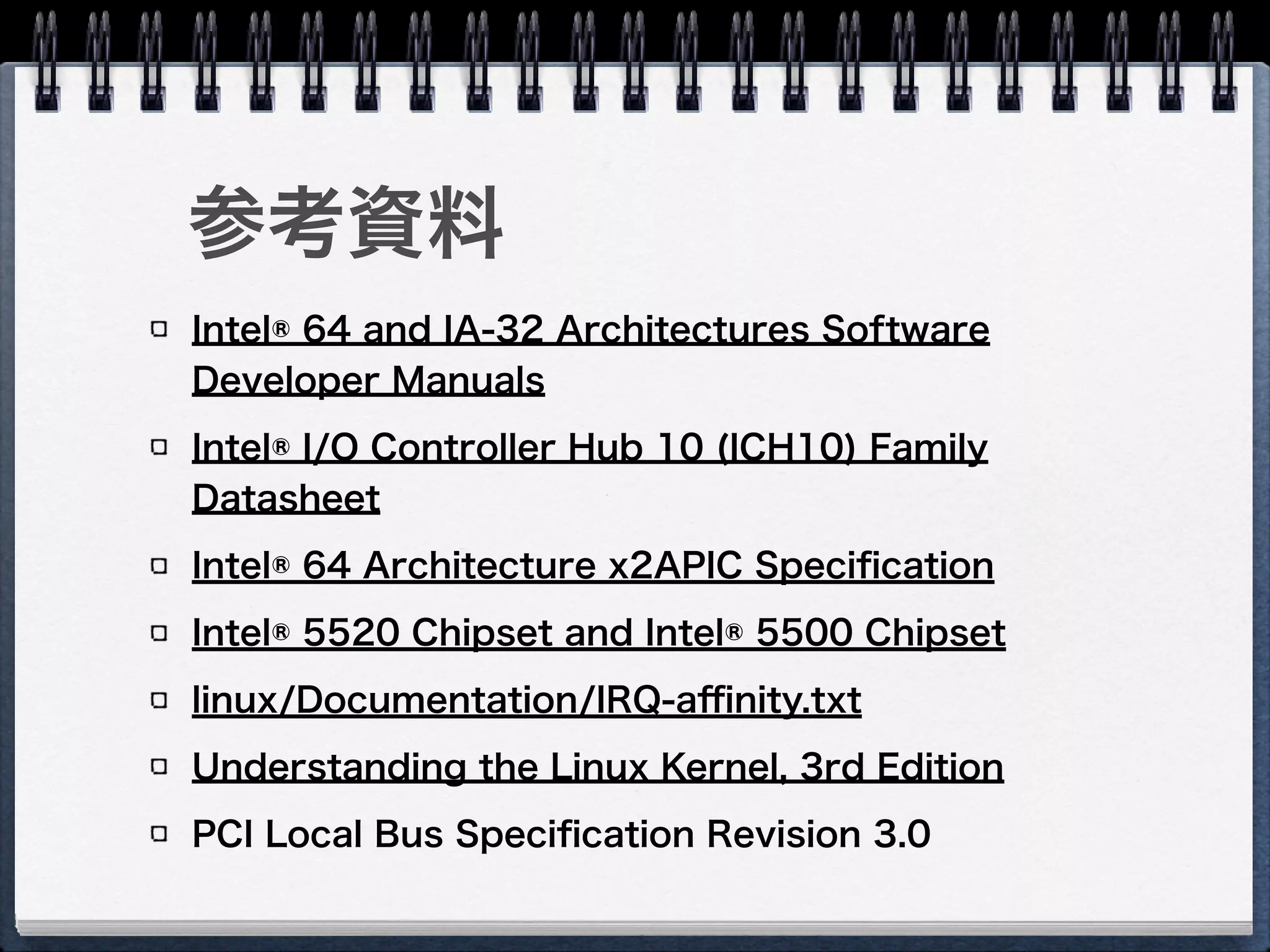
42. 43. 44. Intel® 64 and IA-32 Architectures Software
Developer Manuals
Intel® I/O Controller Hub 10 (ICH10) Family
Datasheet
Intel® 64 Architecture x2APIC Specification
Intel® 5520 Chipset and Intel® 5500 Chipset
linux/Documentation/IRQ-affinity.txt
Understanding the Linux Kernel, 3rd Edition
PCI Local Bus Specification Revision 3.0
参考資料
45.


![# lspci -vvvv -s 00:19.0
00:19.0 Ethernet controller: Intel Corporation 82567LM Gigabit Network Connection (rev 03)
Subsystem: Lenovo Device 20ee
Control: I/O+ Mem+ BusMaster+ SpecCycle- MemWINV- VGASnoop- ParErr- Stepping- SERR+ FastB2B- DisINTx+
Status: Cap+ 66MHz- UDF- FastB2B- ParErr- DEVSEL=fast >TAbort- <TAbort- <MAbort- >SERR- <PERR- INTx-
Latency: 0
Interrupt: pin A routed to IRQ 44
Region 0: Memory at f2600000 (32-bit, non-prefetchable) [size=128K]
Region 1: Memory at f2625000 (32-bit, non-prefetchable) [size=4K]
Region 2: I/O ports at 1840 [size=32]
Capabilities: [c8] Power Management version 2
Flags: PMEClk- DSI+ D1- D2- AuxCurrent=0mA PME(D0+,D1-,D2-,D3hot+,D3cold+)
Status: D0 NoSoftRst- PME-Enable- DSel=0 DScale=1 PME-
Capabilities: [d0] MSI: Enable+ Count=1/1 Maskable- 64bit+
Address: 00000000fee0300c Data: 41b9
Capabilities: [e0] PCI Advanced Features
AFCap: TP+ FLR+
AFCtrl: FLR-
AFStatus: TP-
Kernel driver in use: e1000e
Kernel modules: e1000e
赤く塗った所がMSIのフィールドだが、これだ
と読めないのでlspciをforkしてMSIフィール
ドを表示するツールを作成
https://gist.github.com/1568777](https://image.slidesharecdn.com/interruptaffinity-140628003728-phpapp01/75/Interrupt-Affinity-40-2048.jpg)


![[CB19] Semzhu-Project – 手で作る組込み向けハイパーバイザと攻撃検知手法の新しい世界 by 朱義文](https://cdn.slidesharecdn.com/ss_thumbnails/semzhu-projectcodeblue2019ja-191211063913-thumbnail.jpg?width=640&height=640&fit=bounds)


