Downloaded 78 times


![55
Stress-Strain Curve for CompressionStress-Strain Curve for Compression
Lightweight Concrete ;
ACI 318, Sect. 8.5, 8.6
sensitive to Eaggregate .
For all parameters involving
Each parameter shall be multiplied by a modification factor
for sand-lightweight conc.
for all-lightweight concrete
If splitting tensile strength, fct , is specified, then
This accounts for the reduced
capacity of lightweight concrete
due to aggregate failure;
Such as:
Shear strength
Splitting resistance
Concrete-rebar bond
For normal weight concrete the averageFor normal weight concrete the average
splitting tensile strength is;splitting tensile strength is;
( )[ ] 0.17.6/ '
≤= cct ffλ
'
cf
( )'
7.6 cct ff ≈
(MacGregor, 5(MacGregor, 5thth
ed., Fig. 3.26)ed., Fig. 3.26)
( ) ( )
( ) '5.1
33
33
12090
ccc
c
fwpsiE
FtLbwFtLb
=
≤≤
75.0
85.0
=
=
λ
λ
λ](https://image.slidesharecdn.com/class27-160420075947/85/Civil-Engineering-Materials-5-320.jpg)


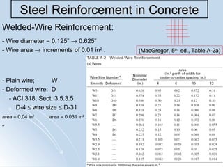


This document discusses stress-strain curves for concrete and steel reinforcement. It provides details on: 1) The stress-strain curve properties for concrete in compression, including the initial slope, ascending parabola, strain at maximum stress, descending parabola, and strain at failure. 2) Methods for determining the tensile strength of concrete, including flexure and split cylinder tests. 3) The use of steel reinforcement bars and welded wire fabric to prevent brittle failure in concrete by taking up tension stresses. Properties of reinforcement bars like diameter, grade, and modulus of elasticity are defined. 4) Factors that affect the yield strength and fatigue strength of steel reinforcement, such as temperature

![Doubly reinforced beam]](https://cdn.slidesharecdn.com/ss_thumbnails/doublyreinforcedbeam-190218110616-thumbnail.jpg?width=640&height=640&fit=bounds)