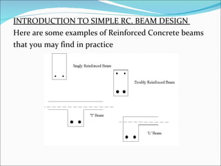
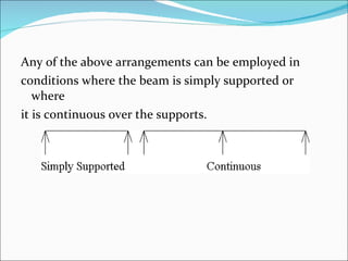
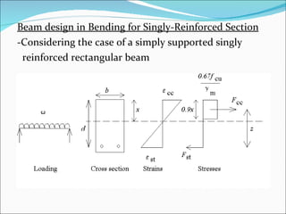
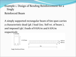
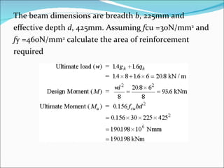
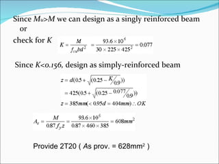
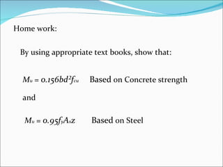
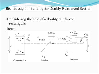
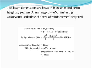
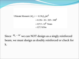
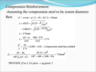
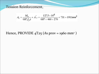
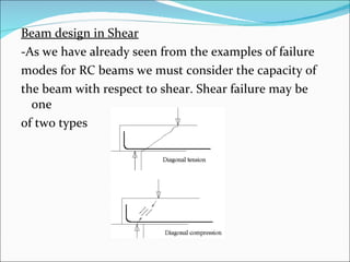
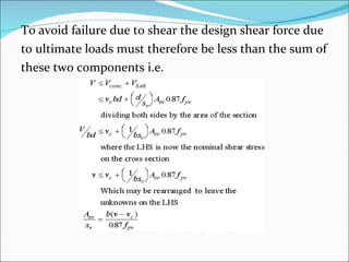
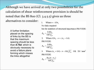
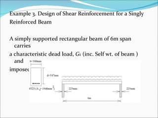
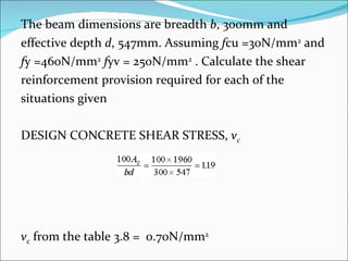
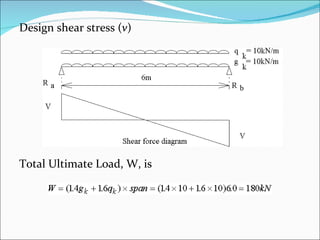
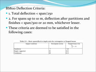
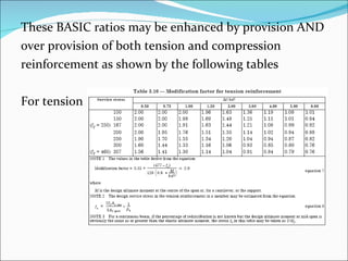
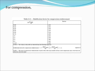
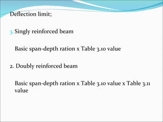
Rectangular and section analysis in bending and shear
Learning out-comes ARUAN EFENDY BIN MOHD GHAZALI  FAKULTI KEJURUTERAAN AWAM At the end of this lecture, the student should be able to: Identify singly and doubly reinforced section (CO1) Design a rectangular section beams in bending, shear and deflection  (CO1, CO2) Details the beams  (CO1).
INTRODUCTION TO SIMPLE RC. BEAM DESIGN  Here are some examples of Reinforced Concrete beams  that you may find in practice
Any of the above arrangements can be employed in  conditions where the beam is simply supported or where  it is continuous over the supports.
Beam design in Bending for Singly-Reinforced Section -Considering the case of a simply supported singly  reinforced rectangular beam
The load causes the beam to deflect downwards  resulting in tension in the bottom of the beam and  compression in the top.  Neutral Axis - The level at which there is neither tension nor compression  OVER-REINFORCED - If a large amount of reinforcement is present then the concrete will fail first in a brittle UNDER-REINFORCED - if the section fails due to yielding of the steel reinforcement first and the failure mode is far more ductile resulting in large deformations, cracking and spalling of concrete on the tension face. As this is highly visible it is a much safer mode of failure, and also is more economical
In an under-reinforced section, since the steel has  yielded we can estimate the ultimate tensile force in the  steel: Where: f y is the yield stress A s is the area of reinforcement γ ms is the partial safety factor for the reinforcement (=1.05)
The applied loading on the beam gives rise to an  Ultimate Design moment ( M ) on the beam in this case  at mid-span. The resulting curvature produces a  compression force in the concrete  F cc and a tensile force  F st in the steel. For equilibrium of horizontal forces:
The two forces are separated by the lever arm,  z  which enables the section to resist the applied moment  and gives the section it’s Ultimate moment of resistance  ( M u). For stability:
which; Due to concrete (in general z=(d-(0.5X0.9x)) hence; 0.156= M/bd²f cu Due to steel reinforcement
Example 1. Design of Bending Reinforcement for a Singly  Reinforced Beam A simply supported rectangular beam of 6m span carries  a characteristic dead ( g k ) load (inc. Self wt. of beam ),  and imposed ( q k ) loads of 8 kN/m and 6 kN/m  respectively
The beam dimensions are breadth  b , 225mm and  effective depth  d , 425mm. Assuming  f cu =30N/mm 2  and  f y =460N/mm 2  calculate the area of reinforcement  required
Since  M u >M  we can design as a singly reinforced beam or check for  K Since  K<0.156,  design as simply-reinforced beam Provide 2T20 (  A s prov. = 628mm 2  )
Home work: By using appropriate text books, show that:  M u  =  0.156bd²f cu Based  on Concrete strength  and M u  =  0.95f y A s z Based  on Steel
Beam design in Bending for Doubly-Reinforced Section -Considering the case of a doubly reinforced rectangular  beam
The area of compression reinforcement is thus  calculated from: where d’ is the depth to the compression steel from the top surface. We must now increase the area of tensile reinforcement to maintain compatibility by an equal amount
where ; and K’ = 0.156
Example 2. Design of Bending Reinforcement for a  Doubly Reinforced Beam A simply supported rectangular beam of 9m span carries  a characteristic dead ( g k ) load (inc. Self wt. of beam ),  and imposed ( q k ) loads of 6 kN/m and 8 kN/m  respectively
The beam dimensions are breadth  b , 225mm and beam  height  h , 400mm. Assuming  f cu =30N/mm 2  and  f y  =460N/mm 2  calculate the area of reinforcement required
Since  we can NOT design as a singly reinforced  beam, we must design as doubly reinforced or check for  k.
Compression Reinforcement -Assuming the compression steel to be 20mm diameter  Bars   PROVIDE 3T20 (  A’ s prov. = 943mm 2  )   
Tension Reinforcement, Hence, PROVIDE 4T25 ( A s prov = 1960 mm 2  )
Beam design in Shear -As we have already seen from the examples of failure  modes for RC beams we must consider the capacity of  the beam with respect to shear. Shear failure may be one  of two types
The first of these, diagonal tension, can be prevented by  the provision of shear links; while the second, diagonal  compression, can be avoided by limiting the maximum  shear stress to 5N/mm 2  or  whichever is the lesser The design shear stress  v , at any cross section is given by: where  V , is the design shear force on the section
Design formulae for link provision: -If we consider a beam under applied shear force  V , the  resulting failure will give rise to a crack which cutsacross  any links as shown:
The failure plane is assumed to lie at an angle of 45° as  shown. The number of links which are therefore  intersected by this failure plane is equal to which allows  us to calculate the shear capacity of the links alone as: The shear resistance of the concrete alone is: *see Table 3.8 for  v c
To avoid failure due to shear the design shear force due  to ultimate loads must therefore be less than the sum of  these two components i.e.
Although we have arrived at only two possibilities for the  calculation of shear reinforcement provision is should be  noted that the BS 8110 (Cl. 3.4.5.5) gives us three  alternatives to consider: A further limitation  placed on the spacing of links by the BS is that the maximum spacing should be less than  0.75d , which is obviously necessary to avoid a failure plane forming which misses the links altogether
Example 3. Design of Shear Reinforcement for a Singly  Reinforced Beam A simply supported rectangular beam of 6m span carries  a characteristic dead load,  G k  (inc. Self wt. of beam ) and  imposed loads ( Q k  ) of 10 kN/m respectively.
The beam dimensions are breadth  b , 300mm and  effective depth  d , 547mm. Assuming  f cu =30N/mm 2  and  f y =460N/mm 2   f yv = 250N/mm 2  . Calculate the shear  reinforcement provision required for each of the  situations given DESIGN CONCRETE SHEAR STRESS,  v c v c  from the table 3.8 =  0.70N/mm 2
Design shear stress ( v ) Total Ultimate Load, W, is
As beam is symmetrically loaded, Ultimate shear force  V =90 kN  and design shear stress,  v ,  is
Diameter and spacing of links By inspection, As described earlier this ratio allows determination of either spacing or area of links. An alternative means of evaluation is presented below: Remembering also that the maximum spacing of links should not exceed 0.75d which in this case equals PROVIDE R10 links at 275 mm(<410mm) centres for the whole length of the beam  (A sv /s v  = 0.571.)
Deflection ( Cl. 3.4.6 . BS8110) BS 8110 details how deflections and the  accompanying crack widths may be calculated. But for  rectangular beams some simplified procedures may be  used to satisfy the requirements without too much  effort. This approximate method for rectangular beams  is based on permissible ratios of span/effective depth.
BS8110 Deflection Criteria: 1. Total deflection < span/250 2. For spans up to 10 m, deflection after partitions and finishes < span/500 or 20 mm, whichever lesser. These criteria are deemed to be satisfied in the following cases:
These BASIC ratios may be enhanced by provision AND  over provision of both tension and compression  reinforcement as shown by the following tables For tension
For compression,
Deflection limit; Singly reinforced beam  Basic span-depth ration x Table 3.10 value 2. Doubly reinforced beam Basic span-depth ration x Table 3.10 value x Table 3.11 value

rectangular and section analysis in bending and shear

  • 1.
    Rectangular and sectionanalysis in bending and shear
  • 2.
    Learning out-comes ARUANEFENDY BIN MOHD GHAZALI FAKULTI KEJURUTERAAN AWAM At the end of this lecture, the student should be able to: Identify singly and doubly reinforced section (CO1) Design a rectangular section beams in bending, shear and deflection (CO1, CO2) Details the beams (CO1).
  • 3.
    INTRODUCTION TO SIMPLERC. BEAM DESIGN Here are some examples of Reinforced Concrete beams that you may find in practice
  • 4.
    Any of theabove arrangements can be employed in conditions where the beam is simply supported or where it is continuous over the supports.
  • 5.
    Beam design inBending for Singly-Reinforced Section -Considering the case of a simply supported singly reinforced rectangular beam
  • 6.
    The load causesthe beam to deflect downwards resulting in tension in the bottom of the beam and compression in the top. Neutral Axis - The level at which there is neither tension nor compression OVER-REINFORCED - If a large amount of reinforcement is present then the concrete will fail first in a brittle UNDER-REINFORCED - if the section fails due to yielding of the steel reinforcement first and the failure mode is far more ductile resulting in large deformations, cracking and spalling of concrete on the tension face. As this is highly visible it is a much safer mode of failure, and also is more economical
  • 7.
    In an under-reinforcedsection, since the steel has yielded we can estimate the ultimate tensile force in the steel: Where: f y is the yield stress A s is the area of reinforcement γ ms is the partial safety factor for the reinforcement (=1.05)
  • 8.
    The applied loadingon the beam gives rise to an Ultimate Design moment ( M ) on the beam in this case at mid-span. The resulting curvature produces a compression force in the concrete F cc and a tensile force F st in the steel. For equilibrium of horizontal forces:
  • 9.
    The two forcesare separated by the lever arm, z which enables the section to resist the applied moment and gives the section it’s Ultimate moment of resistance ( M u). For stability:
  • 10.
    which; Due toconcrete (in general z=(d-(0.5X0.9x)) hence; 0.156= M/bd²f cu Due to steel reinforcement
  • 11.
    Example 1. Designof Bending Reinforcement for a Singly Reinforced Beam A simply supported rectangular beam of 6m span carries a characteristic dead ( g k ) load (inc. Self wt. of beam ), and imposed ( q k ) loads of 8 kN/m and 6 kN/m respectively
  • 12.
    The beam dimensionsare breadth b , 225mm and effective depth d , 425mm. Assuming f cu =30N/mm 2 and f y =460N/mm 2 calculate the area of reinforcement required
  • 13.
    Since Mu >M we can design as a singly reinforced beam or check for K Since K<0.156, design as simply-reinforced beam Provide 2T20 ( A s prov. = 628mm 2 )
  • 14.
    Home work: Byusing appropriate text books, show that: M u = 0.156bd²f cu Based on Concrete strength and M u = 0.95f y A s z Based on Steel
  • 15.
    Beam design inBending for Doubly-Reinforced Section -Considering the case of a doubly reinforced rectangular beam
  • 16.
    The area ofcompression reinforcement is thus calculated from: where d’ is the depth to the compression steel from the top surface. We must now increase the area of tensile reinforcement to maintain compatibility by an equal amount
  • 17.
    where ; andK’ = 0.156
  • 18.
    Example 2. Designof Bending Reinforcement for a Doubly Reinforced Beam A simply supported rectangular beam of 9m span carries a characteristic dead ( g k ) load (inc. Self wt. of beam ), and imposed ( q k ) loads of 6 kN/m and 8 kN/m respectively
  • 19.
    The beam dimensionsare breadth b , 225mm and beam height h , 400mm. Assuming f cu =30N/mm 2 and f y =460N/mm 2 calculate the area of reinforcement required
  • 20.
    Since wecan NOT design as a singly reinforced beam, we must design as doubly reinforced or check for k.
  • 21.
    Compression Reinforcement -Assumingthe compression steel to be 20mm diameter Bars PROVIDE 3T20 ( A’ s prov. = 943mm 2 )  
  • 22.
    Tension Reinforcement, Hence,PROVIDE 4T25 ( A s prov = 1960 mm 2 )
  • 23.
    Beam design inShear -As we have already seen from the examples of failure modes for RC beams we must consider the capacity of the beam with respect to shear. Shear failure may be one of two types
  • 24.
    The first ofthese, diagonal tension, can be prevented by the provision of shear links; while the second, diagonal compression, can be avoided by limiting the maximum shear stress to 5N/mm 2 or whichever is the lesser The design shear stress v , at any cross section is given by: where V , is the design shear force on the section
  • 25.
    Design formulae forlink provision: -If we consider a beam under applied shear force V , the resulting failure will give rise to a crack which cutsacross any links as shown:
  • 26.
    The failure planeis assumed to lie at an angle of 45° as shown. The number of links which are therefore intersected by this failure plane is equal to which allows us to calculate the shear capacity of the links alone as: The shear resistance of the concrete alone is: *see Table 3.8 for v c
  • 27.
    To avoid failuredue to shear the design shear force due to ultimate loads must therefore be less than the sum of these two components i.e.
  • 28.
    Although we havearrived at only two possibilities for the calculation of shear reinforcement provision is should be noted that the BS 8110 (Cl. 3.4.5.5) gives us three alternatives to consider: A further limitation placed on the spacing of links by the BS is that the maximum spacing should be less than 0.75d , which is obviously necessary to avoid a failure plane forming which misses the links altogether
  • 29.
    Example 3. Designof Shear Reinforcement for a Singly Reinforced Beam A simply supported rectangular beam of 6m span carries a characteristic dead load, G k (inc. Self wt. of beam ) and imposed loads ( Q k ) of 10 kN/m respectively.
  • 30.
    The beam dimensionsare breadth b , 300mm and effective depth d , 547mm. Assuming f cu =30N/mm 2 and f y =460N/mm 2 f yv = 250N/mm 2 . Calculate the shear reinforcement provision required for each of the situations given DESIGN CONCRETE SHEAR STRESS, v c v c from the table 3.8 = 0.70N/mm 2
  • 31.
    Design shear stress( v ) Total Ultimate Load, W, is
  • 32.
    As beam issymmetrically loaded, Ultimate shear force V =90 kN and design shear stress, v , is
  • 33.
    Diameter and spacingof links By inspection, As described earlier this ratio allows determination of either spacing or area of links. An alternative means of evaluation is presented below: Remembering also that the maximum spacing of links should not exceed 0.75d which in this case equals PROVIDE R10 links at 275 mm(<410mm) centres for the whole length of the beam (A sv /s v = 0.571.)
  • 34.
    Deflection ( Cl.3.4.6 . BS8110) BS 8110 details how deflections and the accompanying crack widths may be calculated. But for rectangular beams some simplified procedures may be used to satisfy the requirements without too much effort. This approximate method for rectangular beams is based on permissible ratios of span/effective depth.
  • 35.
    BS8110 Deflection Criteria:1. Total deflection < span/250 2. For spans up to 10 m, deflection after partitions and finishes < span/500 or 20 mm, whichever lesser. These criteria are deemed to be satisfied in the following cases:
  • 36.
    These BASIC ratiosmay be enhanced by provision AND over provision of both tension and compression reinforcement as shown by the following tables For tension
  • 37.
  • 38.
    Deflection limit; Singlyreinforced beam Basic span-depth ration x Table 3.10 value 2. Doubly reinforced beam Basic span-depth ration x Table 3.10 value x Table 3.11 value