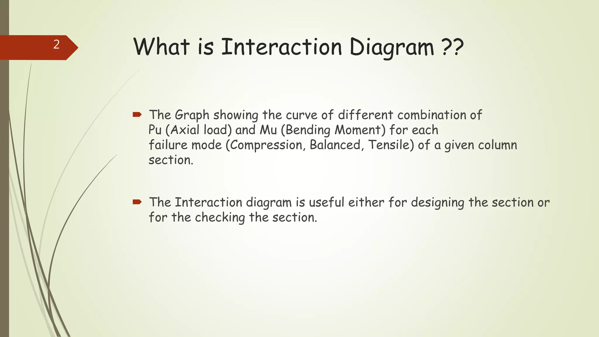
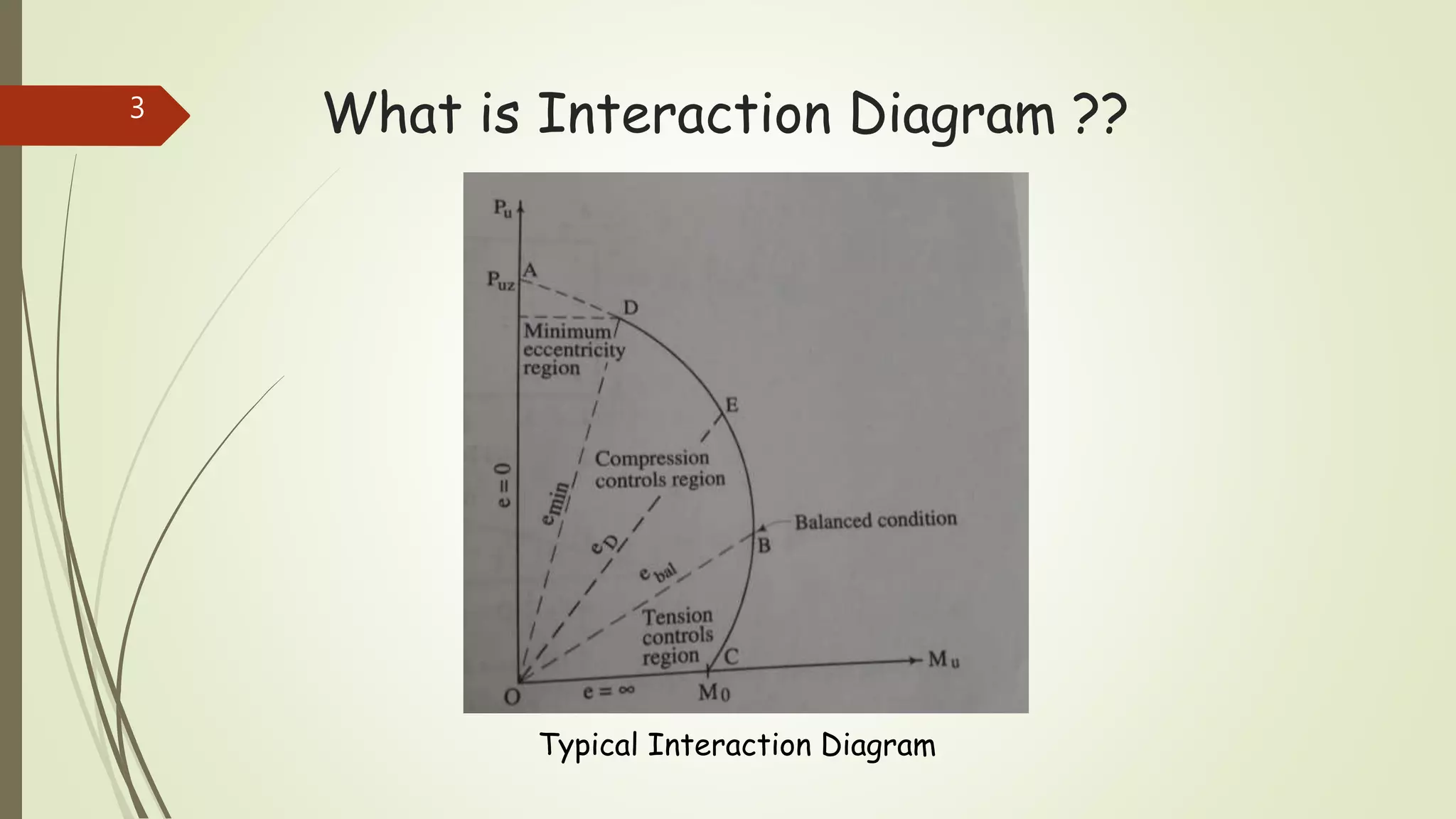
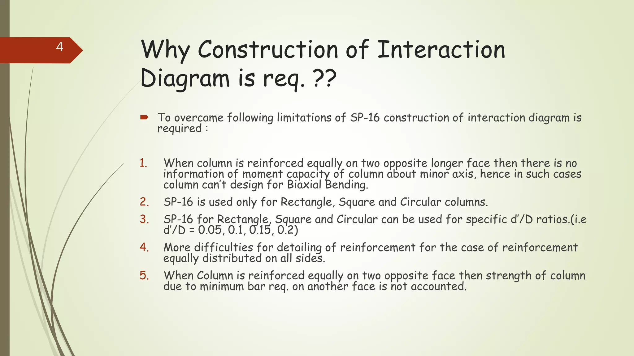
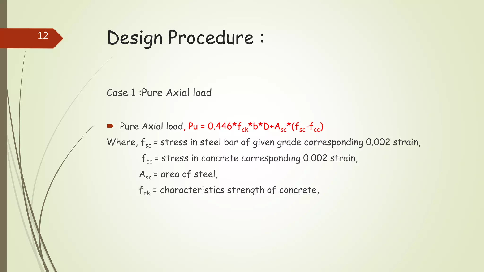
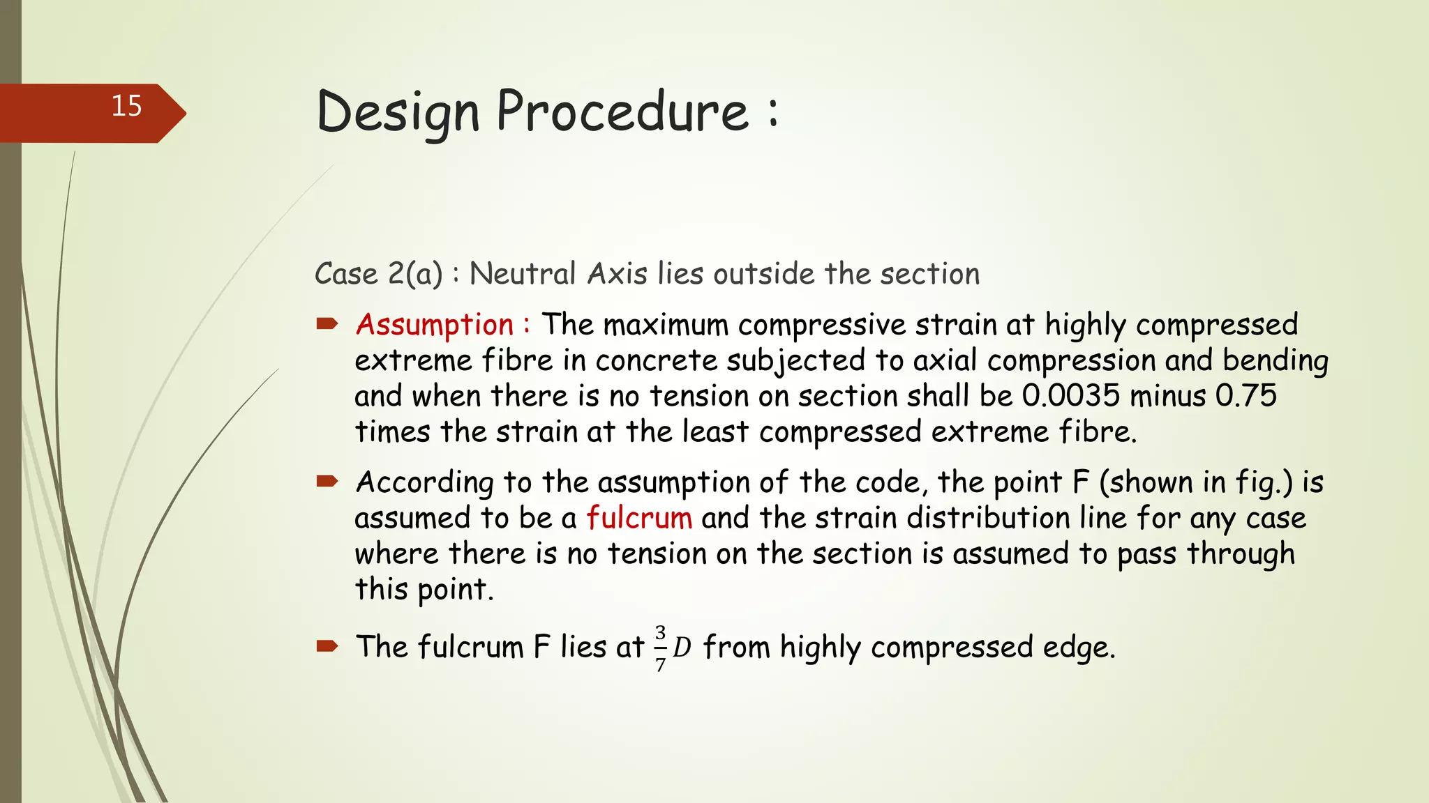
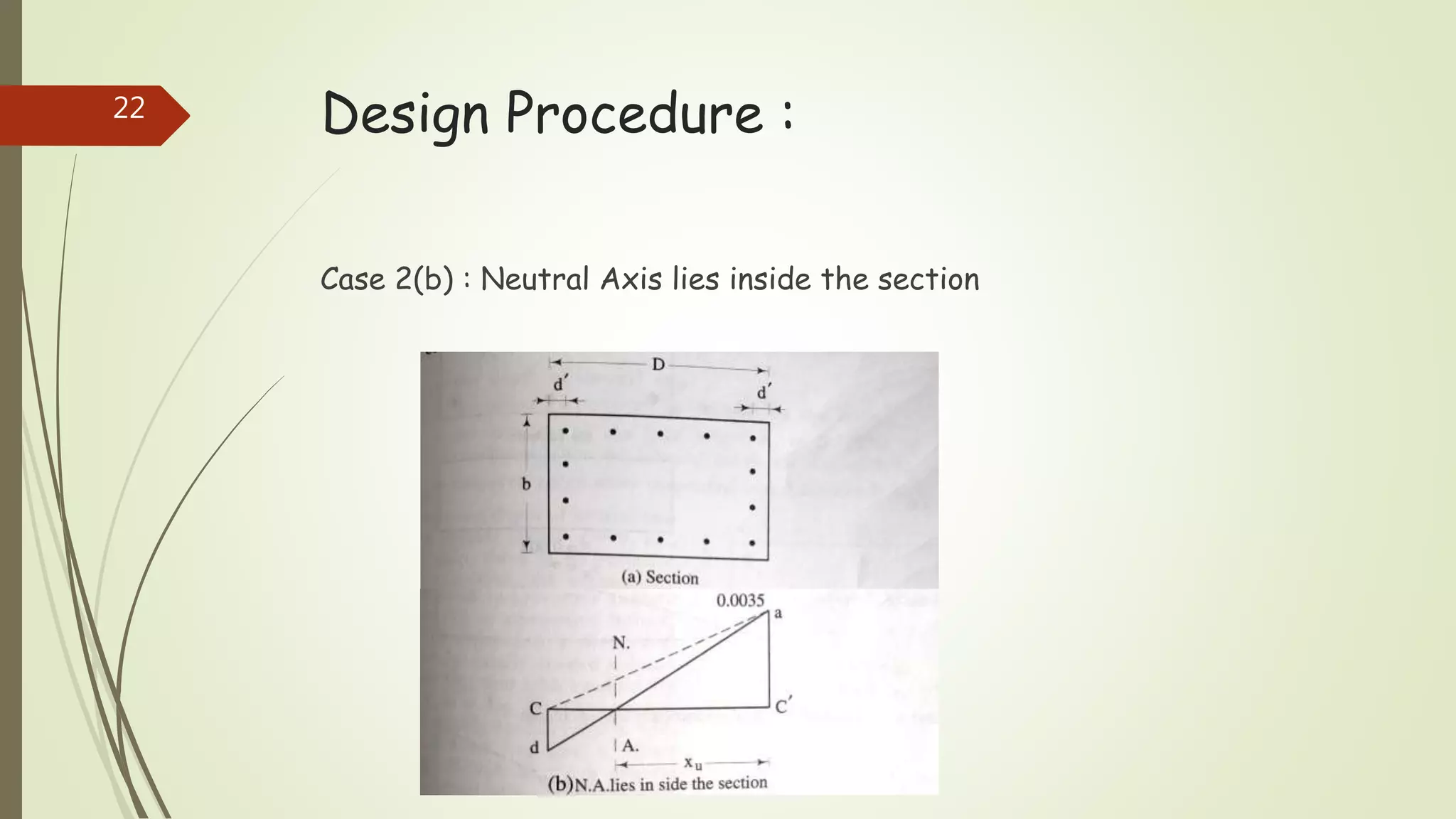
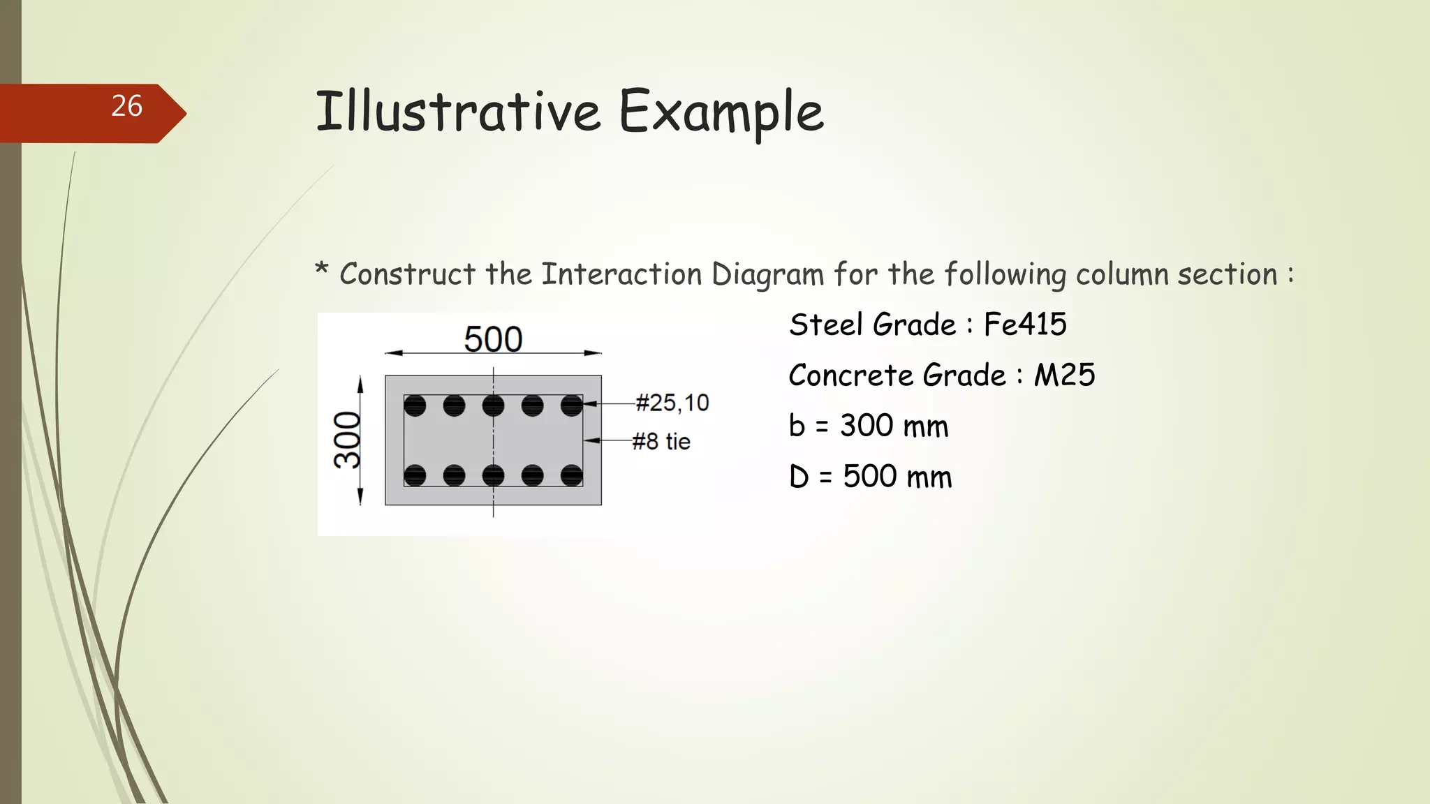
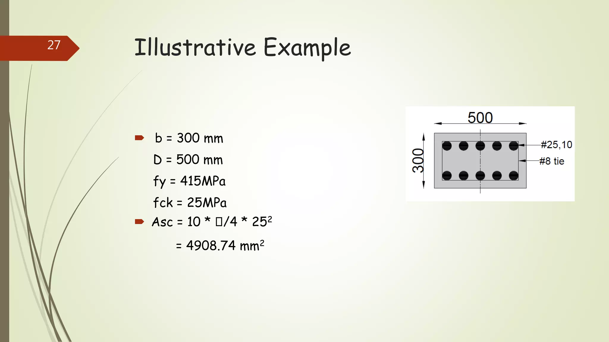
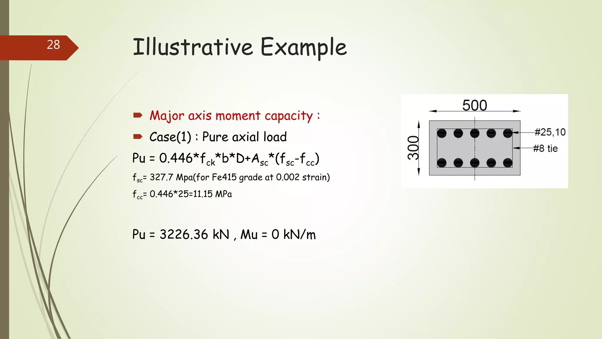
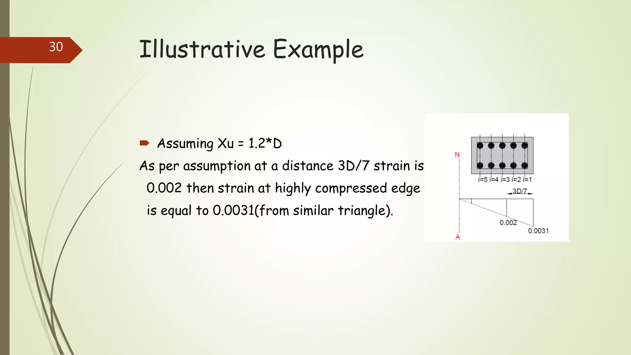
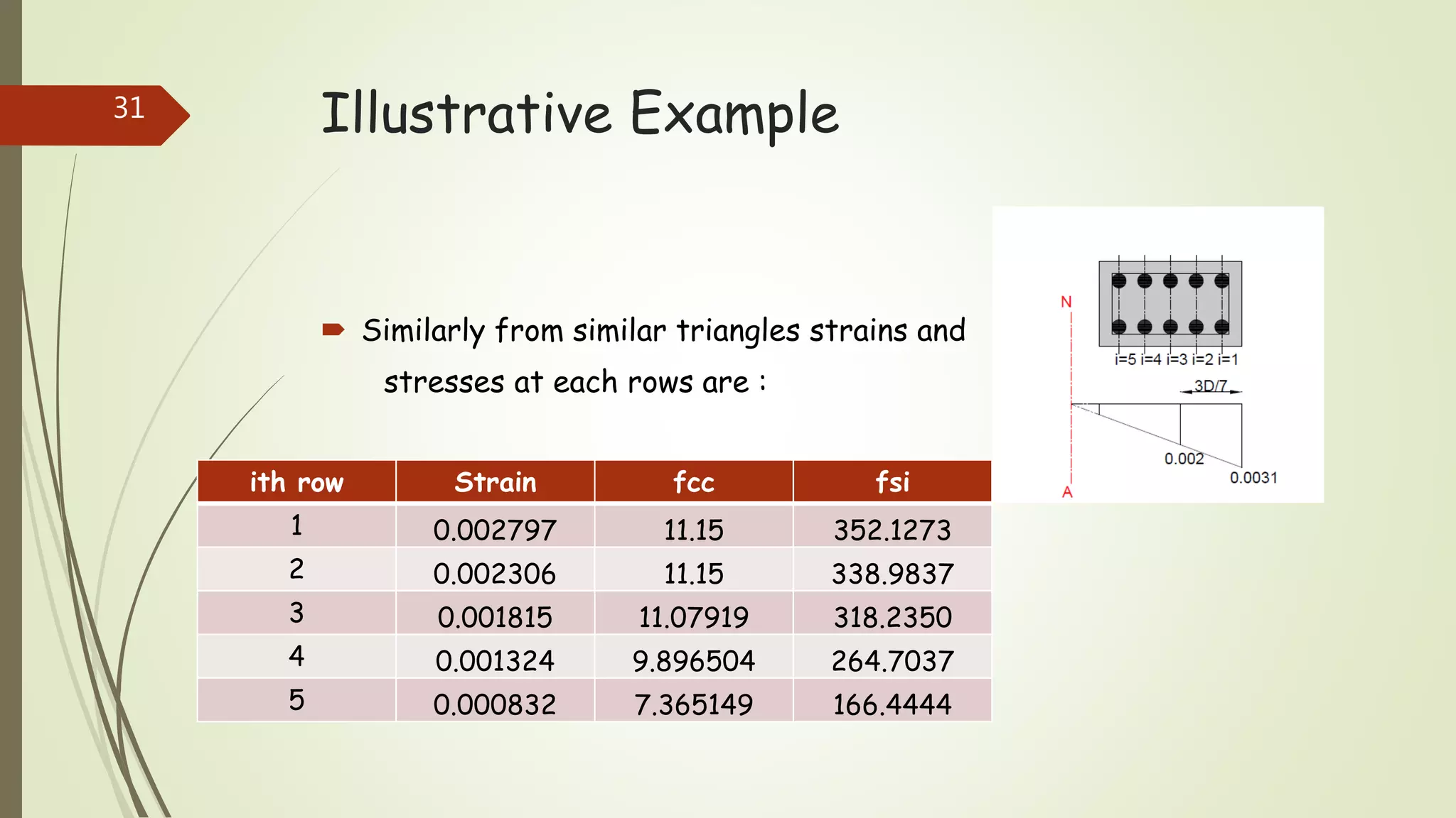
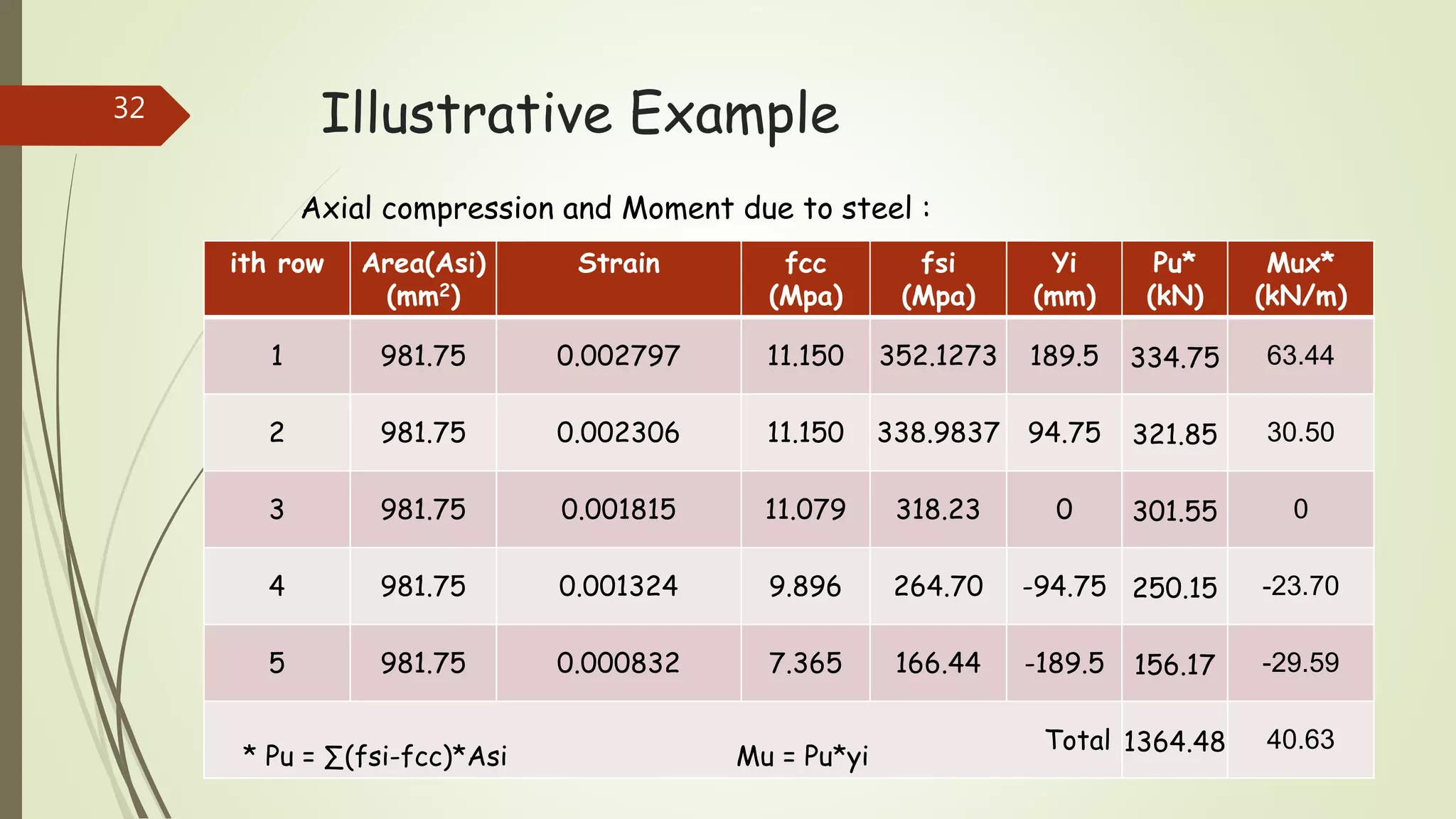
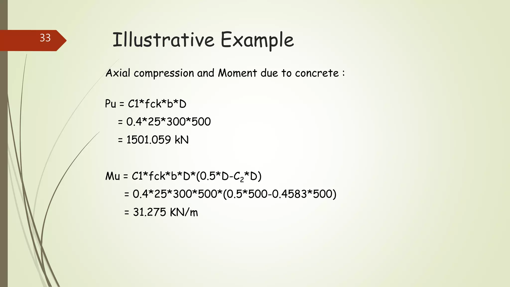
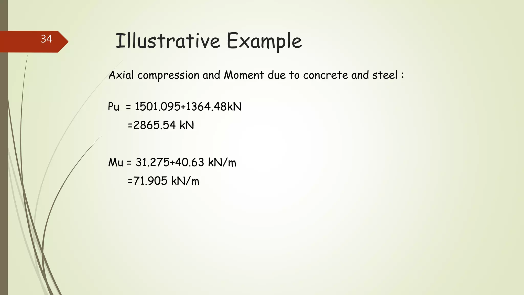
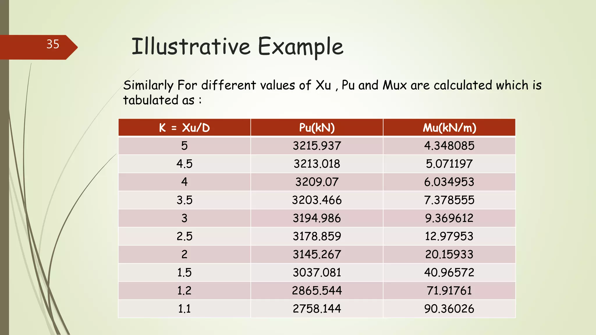
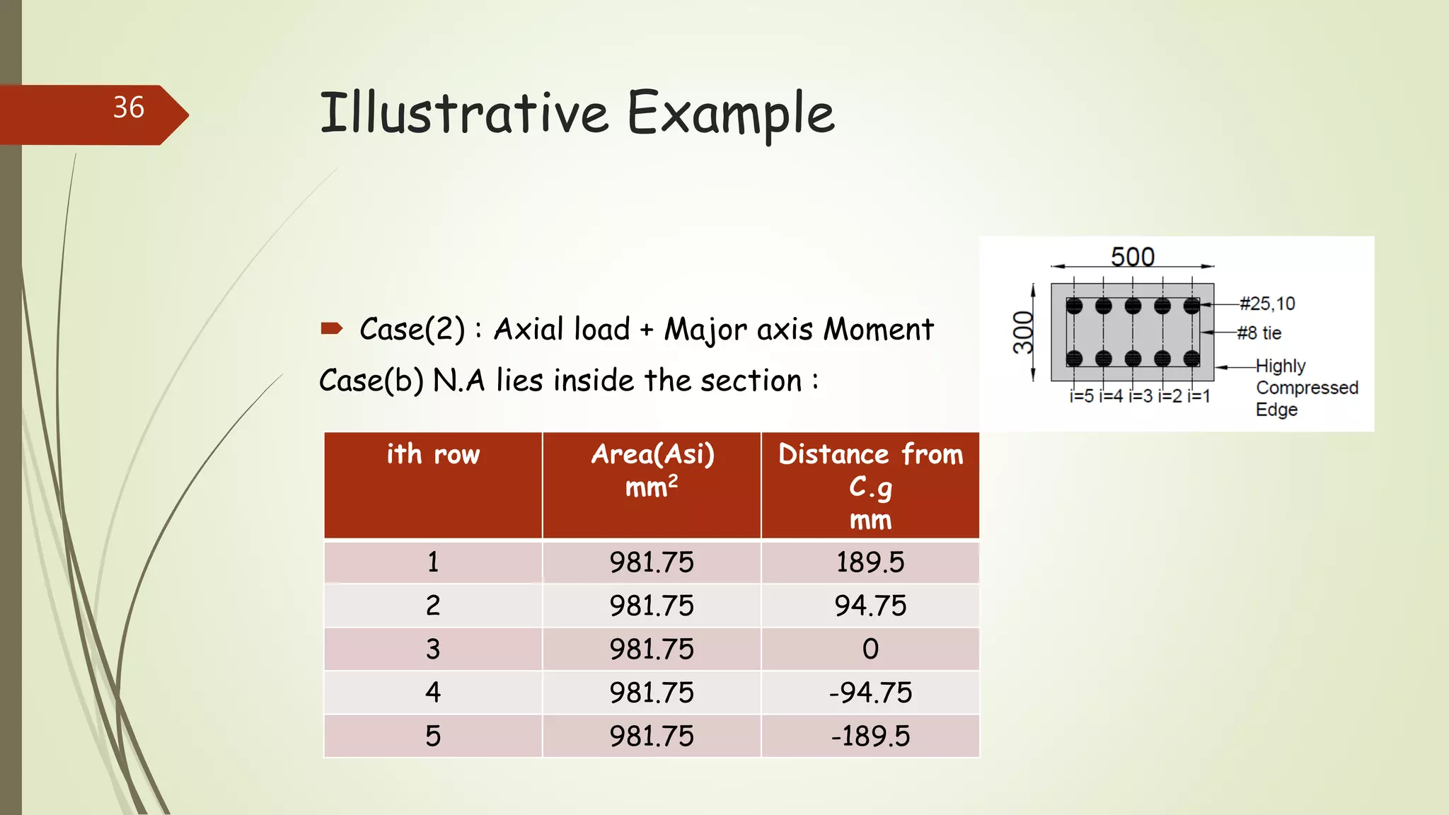
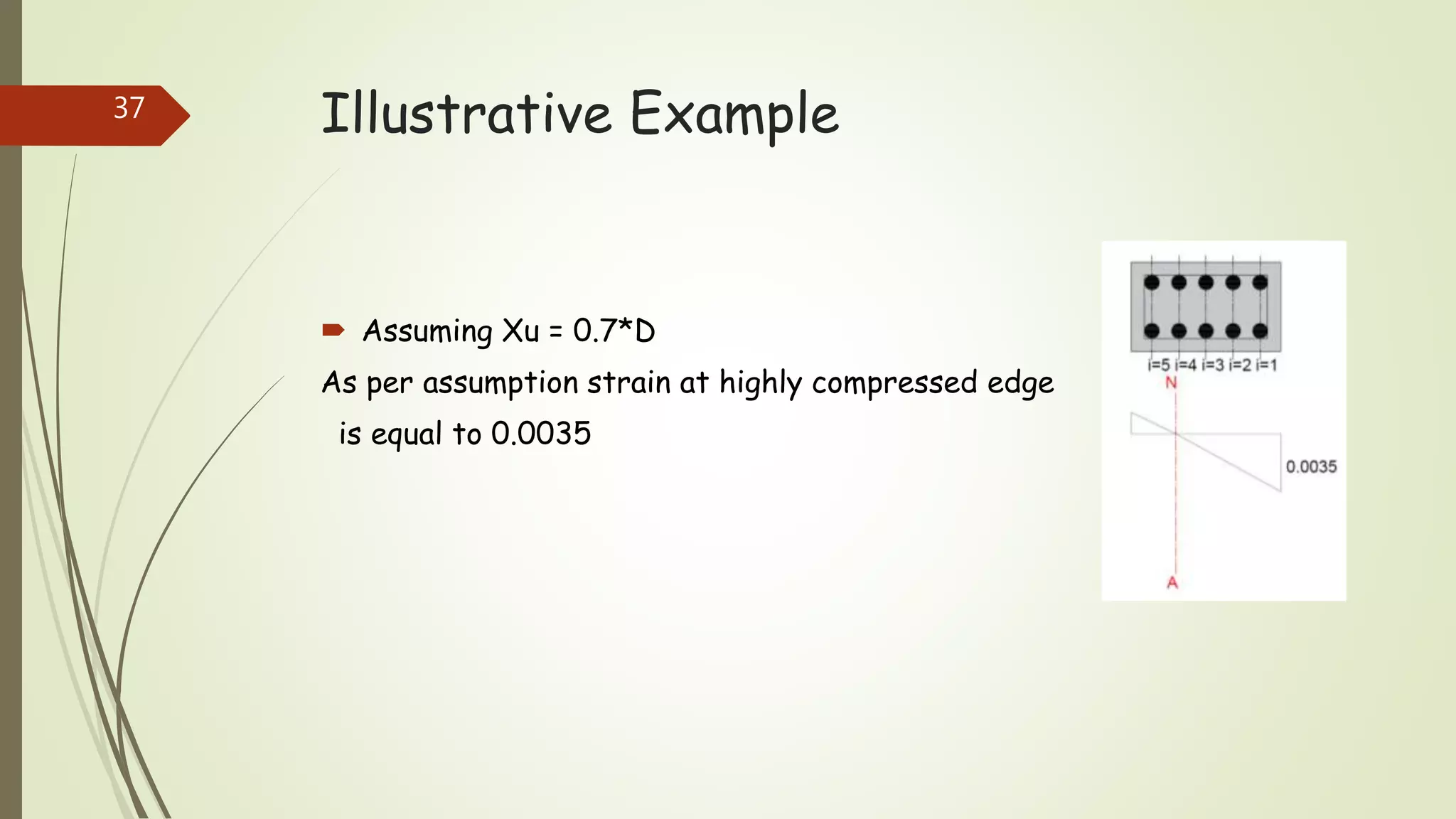
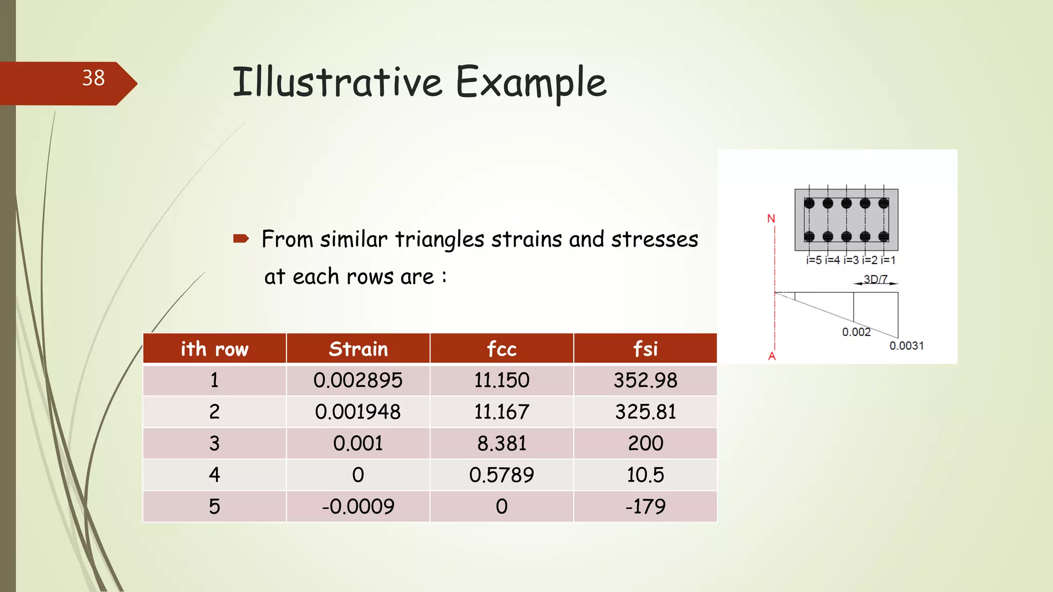
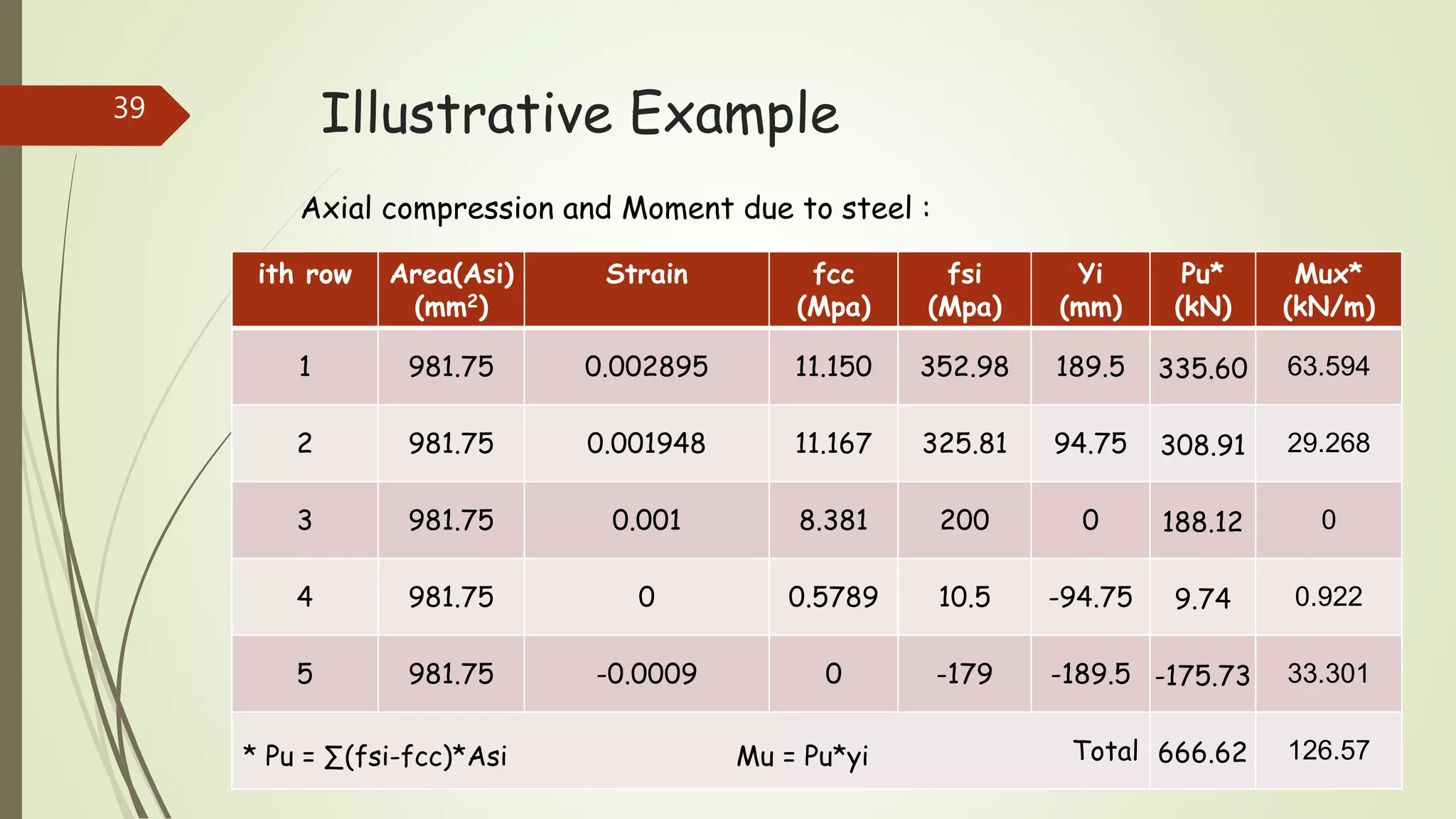
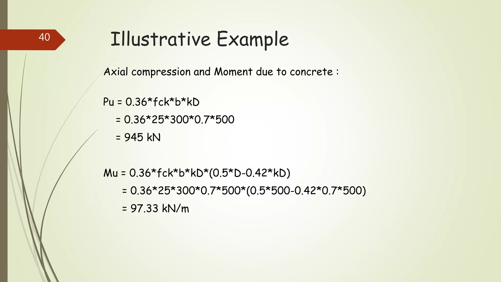
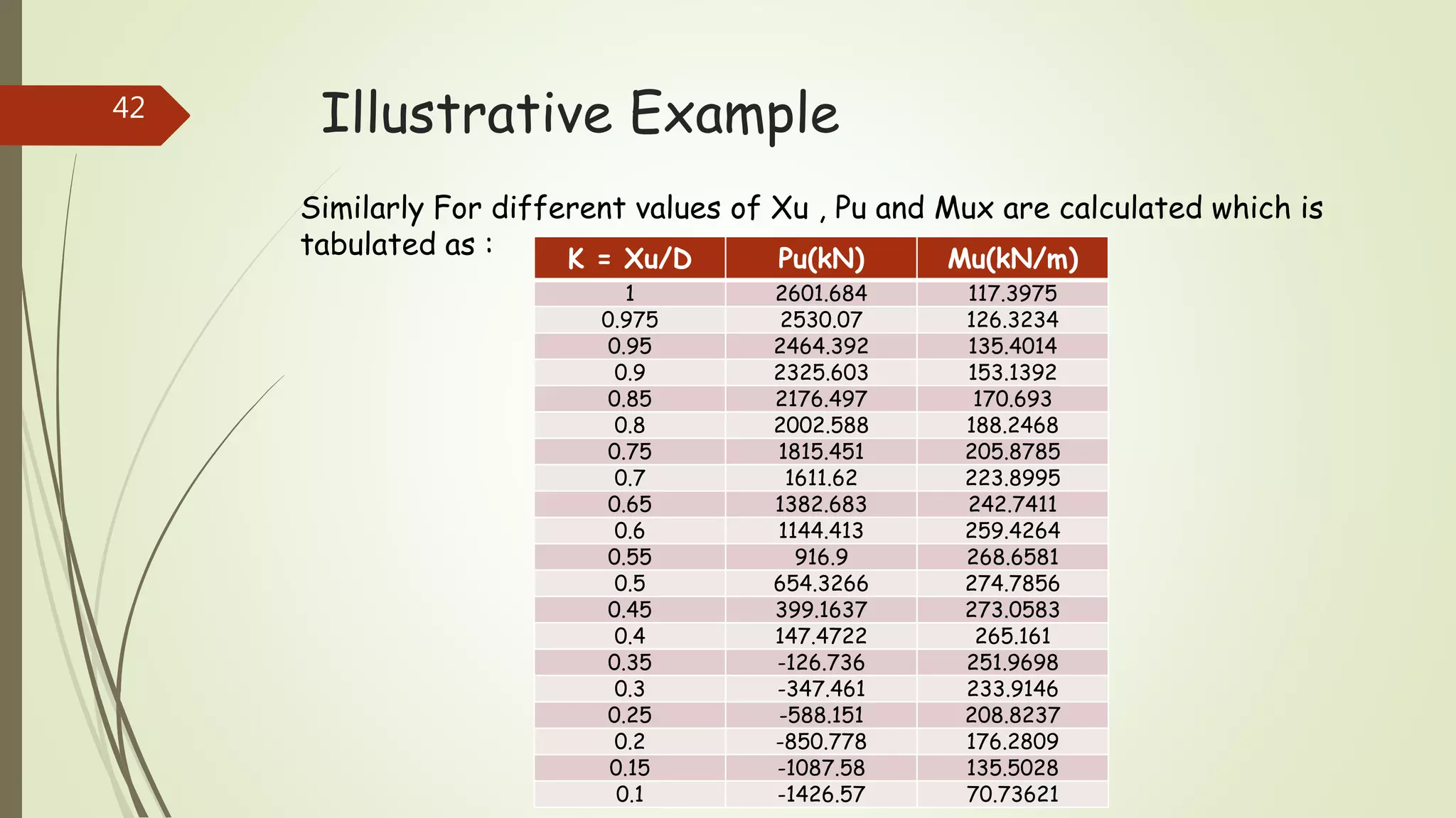
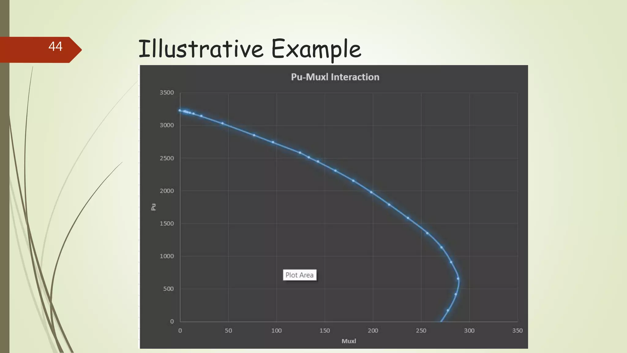
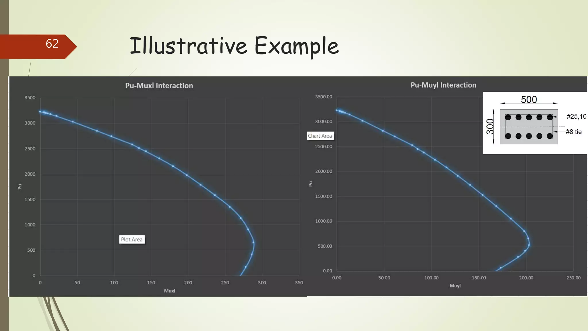
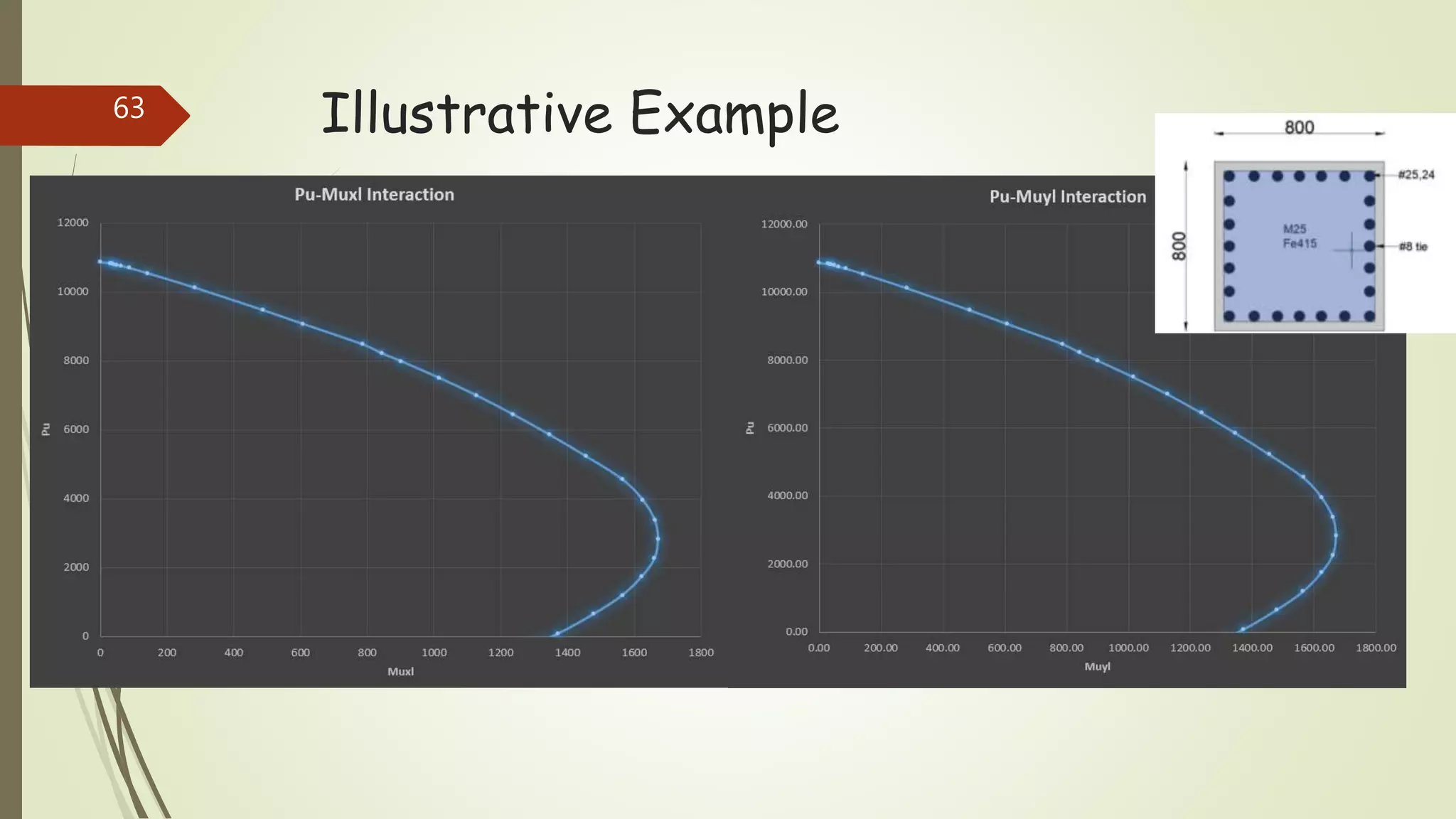
Construction of Interaction
Diagram For Columns
~Pritesh Parmar
Semster -8
Department of Civil Engineering, DDU.
1
What is Interaction Diagram ??
 The Graph showing the curve of different combination of
Pu (Axial load) and Mu (Bending Moment) for each
failure mode (Compression, Balanced, Tensile) of a given column
section.
 The Interaction diagram is useful either for designing the section or
for the checking the section.
2
What is Interaction Diagram ??
Typical Interaction Diagram
3
Why Construction of Interaction
Diagram is req. ??
 To overcame following limitations of SP-16 construction of interaction diagram is
required :
1. When column is reinforced equally on two opposite longer face then there is no
information of moment capacity of column about minor axis, hence in such cases
column can’t design for Biaxial Bending.
2. SP-16 is used only for Rectangle, Square and Circular columns.
3. SP-16 for Rectangle, Square and Circular can be used for specific d’/D ratios.(i.e
d’/D = 0.05, 0.1, 0.15, 0.2)
4. More difficulties for detailing of reinforcement for the case of reinforcement
equally distributed on all sides.
5. When Column is reinforced equally on two opposite face then strength of column
due to minimum bar req. on another face is not accounted.
4
Design Strength of Concrete :5
Design Strength of Concrete :
Design Compressive stress fc :
6
Design Strength of Reinforcing Steel:7
Design Strength of Reinforcing Steel:
Strain level Strain Stress
Up to 0.8 fyd
Stress / Modulus of
Elasticity
Strain * Modulus of
Elasticity
0.8 fyd 0.00144 288.7
0.85 fyd 0.00163 306.7
0.9 fyd 0.00192 324.8
0.95 fyd 0.00241 342.8
0.975 fyd 0.00276 351.8
1.0 fyd 0.00380 360.9
Stress – Strain Relationship for Fe415 grade steel
8
Design Strength of Reinforcing Steel:
Strain level Strain Stress
Up to 0.8 fyd
Stress / Modulus of
Elasticity
Strain * Modulus of
Elasticity
0.8 fyd 0.00174 347.8
0.85 fyd 0.00195 369.6
0.9 fyd 0.00226 391.3
0.95 fyd 0.00277 413.0
0.975 fyd 0.00312 423.9
1.0 fyd 0.00417 434.8
Stress – Strain Relationship for Fe500 grade steel
9
Design Procedure :
 The Interaction Diagram are constructed for Pu versus Mu for
Different values of pt , where is pt percentage of Reinforcement.
 Base on loading conditions they are classified as :
1. Pure Axial Load,
2. Axial load with Uniaxial moment,
3. Axial load with Biaxial moment.
10
Design Procedure :
Case 1 :Pure Axial load
 Assumption :The maximum compressive strain in concrete under axial loading
at the limit state of collapse in compression is specified as εc = 0.002 by the
Code (Cl. 39.1a).
 Corresponding to this limiting strain of 0.002, the design stress in the
concrete is 0.67fck/1.5 = 0.446fck and the design stress in steel is
interpolated from table of stress-strain relationship.
11
Design Procedure :
Case 1 :Pure Axial load
 Pure Axial load, Pu = 0.446*fck*b*D+Asc*(fsc-fcc)
Where, fsc = stress in steel bar of given grade corresponding 0.002 strain,
fcc = stress in concrete corresponding 0.002 strain,
Asc = area of steel,
fck = characteristics strength of concrete,
12
Design Procedure :
Case 2 : Axial load with uniaxial moment
 When the column is subjected to an axial load and uniaxial moment, the
following procedure is applied :
1. Assume different positions of Neutral Axis(N.A),
2. Draw strain and stress diagrams,
3. Calculate stresses in reinforcement from strains,
4. Equate ∑V = 0 , ∑M = 0 and find Capacity of column.
13
Design Procedure :
Case 2 : Axial load with uniaxial moment
 Following two cases occur in design :
a) Neutral Axis lies outside the section,
b) Neutral Axis lies inside the section.
14
Design Procedure :
Case 2(a) : Neutral Axis lies outside the section
 Assumption : The maximum compressive strain at highly compressed
extreme fibre in concrete subjected to axial compression and bending
and when there is no tension on section shall be 0.0035 minus 0.75
times the strain at the least compressed extreme fibre.
 According to the assumption of the code, the point F (shown in fig.) is
assumed to be a fulcrum and the strain distribution line for any case
where there is no tension on the section is assumed to pass through
this point.
 The fulcrum F lies at
3
7
𝐷 from highly compressed edge.
15
Design Procedure :
Case 2(a) : Neutral Axis lies outside the section
16
Design Procedure :
Case 2(a) : Neutral Axis lies outside the section
17
Design Procedure :
Case 2(a) : Neutral Axis lies outside the section
 Stress block parameter when N.A. lies outside the section :
 Area of stress block A = C1*fck*D
C1 = 0.446* 1 −
4
21
4
7𝑘−3
2
 Centroid of stress block from highly compressed edge = C2*D
C2 =
0.223∗𝑓𝑐𝑘−
8
49
∗𝑔
𝐶1
∗𝑓𝑐𝑘
𝑔 =0.446 ∗fck*
4
7𝑘−3
2
18
Design Procedure :
Case 2(a) : Neutral Axis lies outside the section
 Axial load, Pu = Cc + ∑Csi
Where, Cc = compression provided by concrete,
Csi = compression provided by ith row of reinforcement.
 Pu = C1*fck*b*D+ 𝑖=1
𝑖=𝑛
. Asi*(fsi-fci)
Where,C1=coefficient for the area of stress block,
n=no. of rows of reinforcement.
19
Design Procedure :
Case 2(a) : Neutral Axis lies outside the section
 Moment, Mu = Cc*(0.5*D-C2*D) + ∑Csi*yi
Where, Cc = compression provided by concrete,
Csi = compression provided by ith row of reinforcement,
yi = Distance from centroid of section to the ith row
(Positive towards highly compressed edge ).
 Mu = C1*fck*b*D*(0.5*D-C2*D)+ 𝑖=1
𝑖=𝑛
. Asi*(fsi-fci)*yi
Where,C1=coefficient for the area of stress block,
C2=Distance of centroid of concrete stress block,
n=no. of rows of reinforcement.
20
Design Procedure :
Case 2(b) : Neutral Axis lies inside the section
 Assumption : The maximum compressive strain at highly compressed
extreme fibre in concrete subjected to axial compression and bending
shall be 0.0035.
21
Design Procedure :
Case 2(b) : Neutral Axis lies inside the section
22
Design Procedure :
Case 2(b) : Neutral Axis lies outside the section
 Stress block parameter when N.A. lies outside the section :
 Area of stress block A = 0.36*fck*kD
 Centroid of stress block from highly compressed edge = 0.42*kD
K=Depth of N.A/D
23
Design Procedure :
Case 2(b) : Neutral Axis lies inside the section
 Axial load, Pu = Cc + ∑Csi
Where, Cc = compression provided by concrete,
Csi = compression provided by ith row of reinforcement.
 Pu = 0.36*fck*b*kD+ 𝑖=1
𝑖=𝑛
. Asi*(fsi-fci)
Where, n=no. of rows of reinforcement.
24
Design Procedure :
Case 2(b) : Neutral Axis lies inside the section
 Moment, Mu = Cc*(0.5*D-0.42*kD) + ∑Csi*yi
Where, Cc = compression provided by concrete,
Csi = compression provided by ith row of reinforcement,
yi = Distance from centroid of section to the ith row
(Positive towards highly compressed edge ).
 Mu = 0.36*fck*b*kD*(0.5*D-0.42*kD)+ 𝑖=1
𝑖=𝑛
. Asi*(fsi-fci)*yi
Where, n=no. of rows of reinforcement.
25
Illustrative Example
* Construct the Interaction Diagram for the following column section :
Steel Grade : Fe415
Concrete Grade : M25
b = 300 mm
D = 500 mm
26
Illustrative Example
 b = 300 mm
D = 500 mm
fy = 415MPa
fck = 25MPa
 Asc = 10 * /4 * 252
= 4908.74 mm2
27
Illustrative Example
 Major axis moment capacity :
 Case(1) : Pure axial load
Pu = 0.446*fck*b*D+Asc*(fsc-fcc)
fsc= 327.7 Mpa(for Fe415 grade at 0.002 strain)
fcc= 0.446*25=11.15 MPa
Pu = 3226.36 kN , Mu = 0 kN/m
28
Illustrative Example
 Case(2) : Axial load + Major axis Moment
Case(a) N.A lies outside the section :
ith row Area(Asi)
mm2
Distance from
C.g
mm
1 981.75 189.5
2 981.75 94.75
3 981.75 0
4 981.75 -94.75
5 981.75 -189.5
29
Illustrative Example
 Assuming Xu = 1.2*D
As per assumption at a distance 3D/7 strain is
0.002 then strain at highly compressed edge
is equal to 0.0031(from similar triangle).
30
Illustrative Example
 Similarly from similar triangles strains and
stresses at each rows are :
ith row Strain fcc fsi
1 0.002797 11.15 352.1273
2 0.002306 11.15 338.9837
3 0.001815 11.07919 318.2350
4 0.001324 9.896504 264.7037
5 0.000832 7.365149 166.4444
31
Illustrative Example
Axial compression and Moment due to steel :
ith row Area(Asi)
(mm2)
Strain fcc
(Mpa)
fsi
(Mpa)
Yi
(mm)
Pu*
(kN)
Mux*
(kN/m)
1 981.75 0.002797 11.150 352.1273 189.5 334.75 63.44
2 981.75 0.002306 11.150 338.9837 94.75 321.85 30.50
3 981.75 0.001815 11.079 318.23 0 301.55 0
4 981.75 0.001324 9.896 264.70 -94.75 250.15 -23.70
5 981.75 0.000832 7.365 166.44 -189.5 156.17 -29.59
Total 1364.48 40.63
* Pu = ∑(fsi-fcc)*Asi Mu = Pu*yi
32
Illustrative Example
Axial compression and Moment due to concrete :
Pu = C1*fck*b*D
= 0.4*25*300*500
= 1501.059 kN
Mu = C1*fck*b*D*(0.5*D-C2*D)
= 0.4*25*300*500*(0.5*500-0.4583*500)
= 31.275 KN/m
33
Illustrative Example
Axial compression and Moment due to concrete and steel :
Pu = 1501.095+1364.48kN
=2865.54 kN
Mu = 31.275+40.63 kN/m
=71.905 kN/m
34
Illustrative Example
Similarly For different values of Xu , Pu and Mux are calculated which is
tabulated as :
K = Xu/D Pu(kN) Mu(kN/m)
5 3215.937 4.348085
4.5 3213.018 5.071197
4 3209.07 6.034953
3.5 3203.466 7.378555
3 3194.986 9.369612
2.5 3178.859 12.97953
2 3145.267 20.15933
1.5 3037.081 40.96572
1.2 2865.544 71.91761
1.1 2758.144 90.36026
35
Illustrative Example
 Case(2) : Axial load + Major axis Moment
Case(b) N.A lies inside the section :
ith row Area(Asi)
mm2
Distance from
C.g
mm
1 981.75 189.5
2 981.75 94.75
3 981.75 0
4 981.75 -94.75
5 981.75 -189.5
36
Illustrative Example
 Assuming Xu = 0.7*D
As per assumption strain at highly compressed edge
is equal to 0.0035
37
Illustrative Example
 From similar triangles strains and stresses
at each rows are :
ith row Strain fcc fsi
1 0.002895 11.150 352.98
2 0.001948 11.167 325.81
3 0.001 8.381 200
4 0 0.5789 10.5
5 -0.0009 0 -179
38
Illustrative Example
Axial compression and Moment due to steel :
ith row Area(Asi)
(mm2)
Strain fcc
(Mpa)
fsi
(Mpa)
Yi
(mm)
Pu*
(kN)
Mux*
(kN/m)
1 981.75 0.002895 11.150 352.98 189.5 335.60 63.594
2 981.75 0.001948 11.167 325.81 94.75 308.91 29.268
3 981.75 0.001 8.381 200 0 188.12 0
4 981.75 0 0.5789 10.5 -94.75 9.74 0.922
5 981.75 -0.0009 0 -179 -189.5 -175.73 33.301
Total 666.62 126.57* Pu = ∑(fsi-fcc)*Asi Mu = Pu*yi
39
Illustrative Example
Axial compression and Moment due to concrete :
Pu = 0.36*fck*b*kD
= 0.36*25*300*0.7*500
= 945 kN
Mu = 0.36*fck*b*kD*(0.5*D-0.42*kD)
= 0.36*25*300*0.7*500*(0.5*500-0.42*0.7*500)
= 97.33 kN/m
40
Illustrative Example
Axial compression and Moment due to concrete and steel :
Pu = 945+666.62kN
=1611.62 kN
Mu = 97.33+126.57 kN/m
=223.90 kN/m
41
Illustrative Example
Similarly For different values of Xu , Pu and Mux are calculated which is
tabulated as : K = Xu/D Pu(kN) Mu(kN/m)
1 2601.684 117.3975
0.975 2530.07 126.3234
0.95 2464.392 135.4014
0.9 2325.603 153.1392
0.85 2176.497 170.693
0.8 2002.588 188.2468
0.75 1815.451 205.8785
0.7 1611.62 223.8995
0.65 1382.683 242.7411
0.6 1144.413 259.4264
0.55 916.9 268.6581
0.5 654.3266 274.7856
0.45 399.1637 273.0583
0.4 147.4722 265.161
0.35 -126.736 251.9698
0.3 -347.461 233.9146
0.25 -588.151 208.8237
0.2 -850.778 176.2809
0.15 -1087.58 135.5028
0.1 -1426.57 70.73621
42
Illustrative Example
Pu(kN) Mu(kN)
3226.36 0
3215.937 4.348085
3213.018 5.071197
3209.07 6.034953
3203.466 7.378555
3194.986 9.369612
3178.859 12.97953
3145.267 20.15933
3037.081 40.96572
2865.544 71.91761
2758.144 90.36026
2601.684 117.3975
2530.07 126.3234
2464.392 135.4014
2325.603 153.1392
2176.497 170.693
2002.588 188.2468
1815.451 205.8785
1611.62 223.8995
1382.683 242.7411
1144.413 259.4264
916.9 268.6581
654.3266 274.7856
399.1637 273.0583
147.4722 265.161
43
Illustrative Example44
Illustrative Example
 Minor axis moment capacity :
 Case(1) : Pure axial load
Pu = 0.446*fck*b*D+Asc*(fsc-fcc)
fsc= 327.7 Mpa(for Fe415 grade at 0.002 strain)
fcc= 0.446*25=11.15 MPa
Pu = 3226.36 kN , Mu = 0 kN/m
45
Illustrative Example
 Case(2) : Axial load + Minor axis Moment
Case(a) N.A lies outside the section :
ith row Area(Asi)
mm2
Distance from
C.g
mm
1 2454.369 89.5
2 2454.369 -89.5
46
Illustrative Example
 Assuming Xu = 1.2*D
As per assumption at a distance 3D/7 strain is
0.002 then strain at highly compressed edge
is equal to 0.0031(from similar triangle).
47
Illustrative Example
 Similarly from similar triangles strains and
stresses at each rows are :
ith row Strain fcc fsi
1 0.002588 11.150 347.384
2 0.001041 8.607 208.271
48
Illustrative Example
Axial compression and Moment due to steel :
ith row Area(Asi)
(mm2)
Strain fcc
(Mpa)
fsi
(Mpa)
Yi
(mm)
Pu*
(kN)
Mux*
(kN/m)
1 2454.369 0.002588 11.150
347.38
4
89.5 825.24 73.859
2 2454.369 0.001041 8.607 208.271 -89.5 490.05 -43.859
Total 1315.29 30* Pu = ∑(fsi-fcc)*Asi Mu = Pu*yi
49
Illustrative Example
Axial compression and Moment due to concrete :
Pu = C1*fck*b*D
= 0.4*25*300*500
= 1501.059kN
Mu = C1*fck*b*D*(0.5*b-C2*b)
= 0.4*25*300*500*(0.5*300-0.4583*300)
= 18.765 kN/m
50
Illustrative Example
Axial compression and Moment due to concrete and steel :
Pu = 1501.059+1315.29kN
=2816.35 kN
Mu = 18.765+30 kN/m
= 48.765 kN/m
51
Illustrative Example
Similarly For different values of Xu , Pu and Mux are calculated which is
tabulated as :
K = Xu/D Pu(kN) Mu(kN/m)
5 3214.642 3.091646
4.5 3211.444 3.597555
4 3207.139 4.267939
3.5 3201.066 5.196079
3 3191.939 6.559853
2.5 3176.922 8.741857
2 3140.547 13.4386
1.5 3019.053 27.27909
1.2 2816.351 48.77028
1.1 2697.741 61.36487
52
Illustrative Example
 Case(2) : Axial load + Minor axis Moment
Case(b) N.A lies inside the section :
ith row Area(Asi)
mm2
Distance from
C.g
mm
1 2454.369 89.5
2 2454.369 -89.5
53
Illustrative Example
 Assuming Xu = 0.7*D
As per assumption strain at highly compressed edge
is equal to 0.0035
54
Illustrative Example
 From similar triangles strains and stresses
at each rows are :
ith row Strain fcc fsi
1 0.002492 11.150 344.9
2 -0.00049 0 -98.33
55
Illustrative Example
Axial compression and Moment due to steel :
ith row Area(Asi)
(mm2)
Strain fcc
(Mpa)
fsi
(Mpa)
Yi
(mm)
Pu*
(kN)
Mux*
(kN/m)
1 2454.369 0.002492 11.150 344.9 89.5 819.15 73.31
2 2454.369 -0.00049 0 -98.33 -89.5 -241.338 21.60
Total 577.79 94.91* Pu = ∑(fsi-fcc)*Asi Mu = Pu*yi
56
Illustrative Example
Axial compression and Moment due to concrete :
Pu = 0.36*fck*b*kD
= 0.36*25*500*0.7*300
= 945 kN
Mu = 0.36*fck*b*kD*(0.5*b-0.42*kb)
= 0.36*25*300*0.7*500*(0.5*300-0.42*0.7*300)
= 59.1948 kN/m
57
Illustrative Example
Axial compression and Moment due to concrete and steel :
Pu = 945+577.799kN
=1522.799 kN
Mu = 59.1948+94.91 kN/m
=154.10 kN/m
58
Illustrative Example
Similarly For different values of Xu , Pu and Mux are calculated which is
tabulated as : K = Xu/D Pu(kN) Mu(kN/m)
1 2524.847 79.5213
0.975 2449.346 85.58437
0.95 2379.494 91.76559
0.9 2232.592 103.8652
0.85 2076.782 115.8647
0.8 1910.48 127.8958
0.75 1725.169 140.7076
0.7 1522.799 154.1088
0.65 1299.681 168.4079
0.6 1048.289 183.8306
0.55 797.861 198.0393
0.5 647.6338 202.0925
0.45 518.0742 202.988
0.4 402.9299 199.1211
0.35 279.7732 191.5421
0.3 59.91849 173.257
0.25 -231.544 147.7206
0.2 -630.099 111.7569
0.15 -1275.06 52.89775
0.1 -1631.37 19.0297
59
Illustrative Example
Pu(kN) Mu(kN)
3226.36 0
3214.642 3.091646
3211.444 3.597555
3207.139 4.267939
3201.066 5.196079
3191.939 6.559853
3176.922 8.741857
3140.547 13.4386
3019.053 27.27909
2816.351 48.77028
2697.741 61.36487
2524.847 79.5213
2449.346 85.58437
2379.494 91.76559
2232.592 103.8652
2076.782 115.8647
1910.48 127.8958
1725.169 140.7076
1522.799 154.1088
1299.681 168.4079
1048.289 183.8306
797.861 198.0393
647.6338 202.0925
518.0742 202.988
402.9299 199.1211
279.7732 191.5421
59.91849 173.257
60
Illustrative Example61
Illustrative Example62
Illustrative Example63
Illustrative Example
* Construct the Interaction Diagram for the following column section :
Steel Grade : Fe415
Concrete Grade : M25
D = 500 mm
64
Illustrative Example
 D = 500 mm
fy = 415MPa
fck = 25MPa
 Asc = 10 * /4 * 202
= 3141.59 mm2
 Ag = /4 * 4002
= 125663.70 mm2
65
Illustrative Example
 Major axis moment capacity :
 Case(1) : Pure axial load
Pu = 0.446*fck* /4 *D2+Asc*(fsc-fcc)
fsc= 327.7 Mpa(for Fe415 grade at 0.002 strain)
fcc= 0.446*25=11.15 MPa
Pu = 2395.62 kN , Mu = 0 kN/m
66
Illustrative Example
 Case(2) : Axial load + Major axis Moment
Case(a) N.A lies outside the section :
ith row Area(Asi)
mm2
Distance from
C.g
mm
1 628.32 135.05
2 628.32 83.46551
3 628.32 0
4 628.32 -83.46551
5 628.32 -135.05
67
Illustrative Example
 Assuming Xu = 1.2*D
As per assumption at a distance 3D/7 strain is
0.002 then strain at highly compressed edge
is equal to 0.0031(from similar triangle).
68
Illustrative Example
 Similarly from similar triangles strains and
stresses at each rows are :
ith row Strain fcc Fsi
1 0.002690 11.150 350.00
2 0.002356 11.150 340.81
3 0.001815 11.079 318.23
4 0.001274 9.7018 254.77
5 0.000939 8.0329 187.89
69
Illustrative Example
Axial compression and Moment due to steel :
ith row Area(Asi)
(mm2)
Strain fcc
(Mpa)
fsi
(Mpa)
Yi
(mm)
Pu*
(kN)
Mux*
(kN/m)
1 628.32 0.002690 11.150 350.00 135.05 212.90 28.852
2 628.32 0.002356 11.150 340.81 83.46551 207.131 17.288
3 628.32 0.001815 11.079 318.23 0 192.989 0
4 628.32 0.001274 9.7018 254.77 -83.46551 153.981 -12.852
5 628.32 0.000939 8.0329 187.89 -135.05 113.007 -15.261
Total 783.523 17.93
* Pu = ∑(fsi-fcc)*Asi Mu = Pu*yi
70
Illustrative Example
Axial compression and Moment due to concrete :
Pu = C1*fck* /4 *D2
= 0.4*25* /4 *4002
= 1257.52kN
Mu = C1*fck* /4 *D2*(0.5*D-C2*D)
= 0.4*25* /4 *4002 *(0.5*400-0.4583*400)
= 20.96 kN/m
71
Illustrative Example
Axial compression and Moment due to concrete and steel :
Pu = 1257.52+783.523kN
=2041.043 kN
Mu = 20.96+17.93 kN/m
=38.89 kN/m
72
Illustrative Example
Similarly For different values of Xu , Pu and Mux are calculated which is
tabulated as :
K = Xu/D Pu(kN) Mu(kN/m)
5 2289.763 2.136539
4.5 2287.699 2.514077
4 2284.877 3.023173
3.5 2280.824 3.742756
3 2274.604 4.826779
2.5 2263.613 6.683625
2 2240.562 10.42133
1.5 2166.762 21.34521
1.2 2041.043 38.89433
1.1 1963.559 49.58864
73
Illustrative Example
 Case(2) : Axial load + Major axis Moment
Case(b) N.A lies inside the section :
ith row Area(Asi)
mm2
Distance from
C.g
mm
1 981.75 189.5
2 981.75 94.75
3 981.75 0
4 981.75 -94.75
5 981.75 -189.5
74
Illustrative Example
 Assuming Xu = 0.7*D
As per assumption strain at highly compressed edge
is equal to 0.0035
75
Illustrative Example
 From similar triangles strains and stresses
at each rows are :
ith row Strain fcc fsi
1 0.002688 349.9518 11.1500
2 0.002043 329.3301 11.1500
3 0.001000 200.0000 8.3813
4 -0.000043 -8.6638 0.0000
5 -0.000688 -137.6251 0.0000
76
Illustrative Example
Axial compression and Moment due to steel :
ith row Area(Asi)
(mm2)
Strain fcc
(Mpa)
fsi
(Mpa)
Yi
(mm)
Pu*
(kN)
Mux*
(kN/m)
1 628.32 0.002688 349.9518 11.1500 135.05 212.875 28.748
2 628.32 0.002043 329.3301 11.1500 83.46551 199.918 16.686
3 628.32 0.001000 200.0000 8.3813 0 120.397 0
4 628.32 -0.000043 -8.6638 0.0000 -83.46551 -5.4436 0.454
5 628.32 -0.000688 -137.6251 0.0000 -135.05 -86.472 11.678
Total 380.995 57.568* Pu = ∑(fsi-fcc)*Asi Mu = Pu*yi
77
Illustrative Example
Axial compression and Moment due to concrete :
Pu = 0.36*fck*area
= 0.36*25*93956.77 area = area of sector OACB + area of triangle OAB
= 845.61 kN =93956.77 mm2
Mu = 0.36*fck*area*(0.5*D-0.42*kD)
= 0.36*25*93956.77 *(0.5*400-0.42*0.7*400)
= 70.625 kN/m
78
Illustrative Example
Axial compression and Moment due to concrete and steel :
Pu = 845.61+380.955kN
=1226.565 kN
Mu = 70.625+57.568 kN/m
=128.193 kN/m
79
Illustrative Example
Similarly For different values of Xu , Pu and Mux are calculated which is
tabulated as : K = Xu/D Pu(kN) Mu(kN/m)
1 1847.789 65.30064
0.975 1815.785 71.33543
0.95 1783.071 77.35583
0.9 1703.045 88.80941
0.85 1608.026 99.51099
0.8 1494.581 109.6482
0.75 1367.655 119.1865
0.7 1226.565 128.1932
0.65 1069.067 137.0112
0.6 892.5082 145.6539
0.55 724.4656 150.6523
0.5 551.6559 152.9305
0.45 393.6139 149.0577
0.4 235.2792 142.0242
0.35 72.90425 131.7054
0.3 -79.1051 118.2974
0.25 -270.178 98.51626
0.2 -518.493 71.12209
0.15 -721.48 44.57439
0.1 -945.626 13.03535
80
Illustrative Example
Pu(kN) Mu(kN)
2395.61 0
2289.763 2.136539
2287.699 2.514077
2284.877 3.023173
2280.824 3.742756
2274.604 4.826779
2263.613 6.683625
2240.562 10.42133
2166.762 21.34521
2041.043 38.89433
1963.559 49.58864
1847.789 65.30064
1815.785 71.33543
1783.071 77.35583
1703.045 88.80941
1608.026 99.51099
1494.581 109.6482
1367.655 119.1865
1226.565 128.1932
1069.067 137.0112
892.5082 145.6539
724.4656 150.6523
551.6559 152.9305
393.6139 149.0577
235.2792 142.0242
81
Illustrative Example82
Illustrative Example
 Minor axis moment capacity :
 Case(1) : Pure axial load
Pu = 0.446*fck* /4 *D2+Asc*(fsc-fcc)
fsc= 327.7 Mpa(for Fe415 grade at 0.002 strain)
fcc= 0.446*25=11.15 MPa
Pu = 2395.62 kN , Mu = 0 kN/m
83
Illustrative Example
 Case(2) : Axial load + Minor axis Moment
Case(a) N.A lies outside the section :
ith row Area(Asi)
mm2
Distance from
C.g
mm
1 314.159 142
2 628.318 115.43
3 628.318 43.88
4 628.318 -43.88
5 628.318 -115.43
6 314.159 142
84
Illustrative Example
 Assuming Xu = 1.2*D
As per assumption at a distance 3D/7 strain is
0.002 then strain at highly compressed edge
is equal to 0.0031(from similar triangle).
85
Illustrative Example
 Similarly from similar triangles strains and
stresses at each rows are :
ith row Strain fcc Fsi
1 0.002735 11.1500 351.1619
2 0.002559 11.1500 346.6420
3 0.002099 11.1500 331.3838
4 0.001530 10.5589 297.2647
5 0.000894 8.7598 214.0439
6 0.000894 7.7603 178.8889
86
Illustrative Example
Axial compression and Moment due to steel :
ith row Area(Asi)
(mm2)
Strain fcc
(Mpa)
fsi
(Mpa)
Yi
(mm)
Pu*
(kN)
Mux*
(kN/m)
1 314.159 0.002735 11.1500 351.1619 142 106.817 15.168
2 628.318 0.002559 11.1500 346.6420 115.43 210.795 24.332
3 628.318 0.002099 11.1500 331.3838 43.88 201.208 8.829
4 628.318 0.001530 10.5589 297.2647 -43.88 180.142 -7.904
5 628.318 0.000894 8.7598 214.0439 -115.43 128.983 -14.888
6 314.159 0.000894 7.7603 178.8889 142 53.7615 -7.634
Total 882.017 17.92
* Pu = ∑(fsi-fcc)*Asi Mu = Pu*yi
87
Illustrative Example
Axial compression and Moment due to concrete :
Pu = C1*fck* /4 *D2
= 0.4*25* /4 *4002
= 1257.52kN
Mu = C1*fck* /4 *D2*(0.5*D-C2*D)
= 0.4*25* /4 *4002 *(0.5*400-0.4583*400)
= 20.96 kN/m
88
Illustrative Example
Axial compression and Moment due to concrete and steel :
Pu = 1257.52+882.022kN
=2139.542 kN
Mu = 20.96+17.93 kN/m
=38.89 kN/m
89
Illustrative Example
Similarly For different values of Xu , Pu and Mux are calculated which is
tabulated as :
K = Xu/D Pu(kN) Mu(kN/m)
5 2389.36 2.128412
4.5 2387.208 2.506113
4 2384.259 3.016103
3.5 2380.038 3.736871
3 2373.585 4.822541
2.5 2362.331 6.673568
2 2338.27 10.46118
1.5 2263.254 21.49601
1.2 2139.542 38.89
1.1 2063.729 49.30666
90
Illustrative Example
 Case(2) : Axial load + Minor axis Moment
Case(b) N.A lies inside the section :
ith row Area(Asi)
mm2
Distance from
C.g
mm
1 314.159 142
2 628.318 115.43
3 628.318 43.88
4 628.318 -43.88
5 628.318 -115.43
6 314.159 -142
91
Illustrative Example
 Assuming Xu = 0.7*D
As per assumption strain at highly compressed edge
is equal to 0.0035
92
Illustrative Example
 From similar triangles strains and stresses
at each rows are :
ith row Strain fcc fsi
1 0.002775 11.1500 351.9313
2 0.002436 11.1500 343.4687
3 0.001549 10.6055 298.9794
4 0.000451 4.4760 90.2990
5 -0.000775 0.0000 -87.2010
6 -0.000436 0.0000 -155.0000
93
Illustrative Example
Axial compression and Moment due to steel :
ith
row
Area(Asi
)
(mm2)
Strain fcc
(Mpa)
fsi
(Mpa)
Yi
(mm)
Pu*
(kN)
Mux*
(kN/m
)
1 314.159 0.002775 11.1500 351.9313 142 107.059 15.202
2 628.318 0.002436 11.1500 343.4687 115.43 208.801 24.101
3 628.318 0.001549 10.6055 298.9794 43.88 181.190 7.950
4 628.318 0.000451 4.4760 90.2990 -43.88 53.924 -2.366
5 628.318 -0.000775 0.0000 -87.2010 -115.43 -54.789 6.324
6 314.159 -0.000436 0.0000 -155.0000 -142 -48.694 6.914
Total 447.68 58.125
94
Illustrative Example
Axial compression and Moment due to concrete :
Pu = 0.36*fck*area
= 0.36*25*93956.77 area = area of sector OACB + area of triangle OAB
= 845.61 kN =93956.77 mm2
Mu = 0.36*fck*area*(0.5*D-0.42*kD)
= 0.36*25*93956.77 *(0.5*400-0.42*0.7*400)
= 70.625 kN/m
95
Illustrative Example
Axial compression and Moment due to concrete and steel :
Pu = 845.61+477.68kN
=1323.29 kN
Mu = 70.625+58.125 kN/m
=128.75 kN/m
96
Illustrative Example
Similarly For different values of Xu , Pu and Mux are calculated which is
tabulated as : K = Xu/D Pu(kN) Mu(kN/m)
1 1946.203 65.11777
0.975 1911.31 71.18564
0.95 1875.557 77.24079
0.9 1789.986 88.79353
0.85 1688.746 99.60895
0.8 1572.112 109.7683
0.75 1440.83 119.4384
0.7 1293.294 128.6088
0.65 1125.112 137.2222
0.6 930.9926 145.2185
0.55 732.088 150.67
0.5 550.6213 151.1498
0.45 360.4001 149.0657
0.4 182.1018 143.4091
0.35 9.406051 132.8055
0.3 -194.348 116.8327
0.25 -400.657 97.81933
0.2 -600.649 74.09924
0.15 -863.611 40.74318
0.1 -1056.64 13.44262
97
Illustrative Example
Pu(kN) Mu(kN)
2359.62 0
2389.36 2.128412
2387.208 2.506113
2384.259 3.016103
2380.038 3.736871
2373.585 4.822541
2362.331 6.673568
2338.27 10.46118
2263.254 21.49601
2139.542 38.82411
2063.729 49.30666
1946.203 65.11777
1911.31 71.18564
1875.557 77.24079
1789.986 88.79353
1688.746 99.60895
1572.112 109.7683
1440.83 119.4384
1293.294 128.6088
1125.112 137.2222
930.9926 145.2185
732.088 150.67
550.6213 151.1498
360.4001 149.0657
182.1018 143.4091
9.406051 132.8055
98
Illustrative Example99
Illustrative Example100
Illustrative Example101
Worksheet
sq_rec column.xlsx
102
THE END
103

Column Interaction Diagram construction

  • 1.
    Construction of Interaction DiagramFor Columns ~Pritesh Parmar Semster -8 Department of Civil Engineering, DDU. 1
  • 2.
    What is InteractionDiagram ??  The Graph showing the curve of different combination of Pu (Axial load) and Mu (Bending Moment) for each failure mode (Compression, Balanced, Tensile) of a given column section.  The Interaction diagram is useful either for designing the section or for the checking the section. 2
  • 3.
    What is InteractionDiagram ?? Typical Interaction Diagram 3
  • 4.
    Why Construction ofInteraction Diagram is req. ??  To overcame following limitations of SP-16 construction of interaction diagram is required : 1. When column is reinforced equally on two opposite longer face then there is no information of moment capacity of column about minor axis, hence in such cases column can’t design for Biaxial Bending. 2. SP-16 is used only for Rectangle, Square and Circular columns. 3. SP-16 for Rectangle, Square and Circular can be used for specific d’/D ratios.(i.e d’/D = 0.05, 0.1, 0.15, 0.2) 4. More difficulties for detailing of reinforcement for the case of reinforcement equally distributed on all sides. 5. When Column is reinforced equally on two opposite face then strength of column due to minimum bar req. on another face is not accounted. 4
  • 5.
    Design Strength ofConcrete :5
  • 6.
    Design Strength ofConcrete : Design Compressive stress fc : 6
  • 7.
    Design Strength ofReinforcing Steel:7
  • 8.
    Design Strength ofReinforcing Steel: Strain level Strain Stress Up to 0.8 fyd Stress / Modulus of Elasticity Strain * Modulus of Elasticity 0.8 fyd 0.00144 288.7 0.85 fyd 0.00163 306.7 0.9 fyd 0.00192 324.8 0.95 fyd 0.00241 342.8 0.975 fyd 0.00276 351.8 1.0 fyd 0.00380 360.9 Stress – Strain Relationship for Fe415 grade steel 8
  • 9.
    Design Strength ofReinforcing Steel: Strain level Strain Stress Up to 0.8 fyd Stress / Modulus of Elasticity Strain * Modulus of Elasticity 0.8 fyd 0.00174 347.8 0.85 fyd 0.00195 369.6 0.9 fyd 0.00226 391.3 0.95 fyd 0.00277 413.0 0.975 fyd 0.00312 423.9 1.0 fyd 0.00417 434.8 Stress – Strain Relationship for Fe500 grade steel 9
  • 10.
    Design Procedure : The Interaction Diagram are constructed for Pu versus Mu for Different values of pt , where is pt percentage of Reinforcement.  Base on loading conditions they are classified as : 1. Pure Axial Load, 2. Axial load with Uniaxial moment, 3. Axial load with Biaxial moment. 10
  • 11.
    Design Procedure : Case1 :Pure Axial load  Assumption :The maximum compressive strain in concrete under axial loading at the limit state of collapse in compression is specified as εc = 0.002 by the Code (Cl. 39.1a).  Corresponding to this limiting strain of 0.002, the design stress in the concrete is 0.67fck/1.5 = 0.446fck and the design stress in steel is interpolated from table of stress-strain relationship. 11
  • 12.
    Design Procedure : Case1 :Pure Axial load  Pure Axial load, Pu = 0.446*fck*b*D+Asc*(fsc-fcc) Where, fsc = stress in steel bar of given grade corresponding 0.002 strain, fcc = stress in concrete corresponding 0.002 strain, Asc = area of steel, fck = characteristics strength of concrete, 12
  • 13.
    Design Procedure : Case2 : Axial load with uniaxial moment  When the column is subjected to an axial load and uniaxial moment, the following procedure is applied : 1. Assume different positions of Neutral Axis(N.A), 2. Draw strain and stress diagrams, 3. Calculate stresses in reinforcement from strains, 4. Equate ∑V = 0 , ∑M = 0 and find Capacity of column. 13
  • 14.
    Design Procedure : Case2 : Axial load with uniaxial moment  Following two cases occur in design : a) Neutral Axis lies outside the section, b) Neutral Axis lies inside the section. 14
  • 15.
    Design Procedure : Case2(a) : Neutral Axis lies outside the section  Assumption : The maximum compressive strain at highly compressed extreme fibre in concrete subjected to axial compression and bending and when there is no tension on section shall be 0.0035 minus 0.75 times the strain at the least compressed extreme fibre.  According to the assumption of the code, the point F (shown in fig.) is assumed to be a fulcrum and the strain distribution line for any case where there is no tension on the section is assumed to pass through this point.  The fulcrum F lies at 3 7 𝐷 from highly compressed edge. 15
  • 16.
    Design Procedure : Case2(a) : Neutral Axis lies outside the section 16
  • 17.
    Design Procedure : Case2(a) : Neutral Axis lies outside the section 17
  • 18.
    Design Procedure : Case2(a) : Neutral Axis lies outside the section  Stress block parameter when N.A. lies outside the section :  Area of stress block A = C1*fck*D C1 = 0.446* 1 − 4 21 4 7𝑘−3 2  Centroid of stress block from highly compressed edge = C2*D C2 = 0.223∗𝑓𝑐𝑘− 8 49 ∗𝑔 𝐶1 ∗𝑓𝑐𝑘 𝑔 =0.446 ∗fck* 4 7𝑘−3 2 18
  • 19.
    Design Procedure : Case2(a) : Neutral Axis lies outside the section  Axial load, Pu = Cc + ∑Csi Where, Cc = compression provided by concrete, Csi = compression provided by ith row of reinforcement.  Pu = C1*fck*b*D+ 𝑖=1 𝑖=𝑛 . Asi*(fsi-fci) Where,C1=coefficient for the area of stress block, n=no. of rows of reinforcement. 19
  • 20.
    Design Procedure : Case2(a) : Neutral Axis lies outside the section  Moment, Mu = Cc*(0.5*D-C2*D) + ∑Csi*yi Where, Cc = compression provided by concrete, Csi = compression provided by ith row of reinforcement, yi = Distance from centroid of section to the ith row (Positive towards highly compressed edge ).  Mu = C1*fck*b*D*(0.5*D-C2*D)+ 𝑖=1 𝑖=𝑛 . Asi*(fsi-fci)*yi Where,C1=coefficient for the area of stress block, C2=Distance of centroid of concrete stress block, n=no. of rows of reinforcement. 20
  • 21.
    Design Procedure : Case2(b) : Neutral Axis lies inside the section  Assumption : The maximum compressive strain at highly compressed extreme fibre in concrete subjected to axial compression and bending shall be 0.0035. 21
  • 22.
    Design Procedure : Case2(b) : Neutral Axis lies inside the section 22
  • 23.
    Design Procedure : Case2(b) : Neutral Axis lies outside the section  Stress block parameter when N.A. lies outside the section :  Area of stress block A = 0.36*fck*kD  Centroid of stress block from highly compressed edge = 0.42*kD K=Depth of N.A/D 23
  • 24.
    Design Procedure : Case2(b) : Neutral Axis lies inside the section  Axial load, Pu = Cc + ∑Csi Where, Cc = compression provided by concrete, Csi = compression provided by ith row of reinforcement.  Pu = 0.36*fck*b*kD+ 𝑖=1 𝑖=𝑛 . Asi*(fsi-fci) Where, n=no. of rows of reinforcement. 24
  • 25.
    Design Procedure : Case2(b) : Neutral Axis lies inside the section  Moment, Mu = Cc*(0.5*D-0.42*kD) + ∑Csi*yi Where, Cc = compression provided by concrete, Csi = compression provided by ith row of reinforcement, yi = Distance from centroid of section to the ith row (Positive towards highly compressed edge ).  Mu = 0.36*fck*b*kD*(0.5*D-0.42*kD)+ 𝑖=1 𝑖=𝑛 . Asi*(fsi-fci)*yi Where, n=no. of rows of reinforcement. 25
  • 26.
    Illustrative Example * Constructthe Interaction Diagram for the following column section : Steel Grade : Fe415 Concrete Grade : M25 b = 300 mm D = 500 mm 26
  • 27.
    Illustrative Example  b= 300 mm D = 500 mm fy = 415MPa fck = 25MPa  Asc = 10 * /4 * 252 = 4908.74 mm2 27
  • 28.
    Illustrative Example  Majoraxis moment capacity :  Case(1) : Pure axial load Pu = 0.446*fck*b*D+Asc*(fsc-fcc) fsc= 327.7 Mpa(for Fe415 grade at 0.002 strain) fcc= 0.446*25=11.15 MPa Pu = 3226.36 kN , Mu = 0 kN/m 28
  • 29.
    Illustrative Example  Case(2): Axial load + Major axis Moment Case(a) N.A lies outside the section : ith row Area(Asi) mm2 Distance from C.g mm 1 981.75 189.5 2 981.75 94.75 3 981.75 0 4 981.75 -94.75 5 981.75 -189.5 29
  • 30.
    Illustrative Example  AssumingXu = 1.2*D As per assumption at a distance 3D/7 strain is 0.002 then strain at highly compressed edge is equal to 0.0031(from similar triangle). 30
  • 31.
    Illustrative Example  Similarlyfrom similar triangles strains and stresses at each rows are : ith row Strain fcc fsi 1 0.002797 11.15 352.1273 2 0.002306 11.15 338.9837 3 0.001815 11.07919 318.2350 4 0.001324 9.896504 264.7037 5 0.000832 7.365149 166.4444 31
  • 32.
    Illustrative Example Axial compressionand Moment due to steel : ith row Area(Asi) (mm2) Strain fcc (Mpa) fsi (Mpa) Yi (mm) Pu* (kN) Mux* (kN/m) 1 981.75 0.002797 11.150 352.1273 189.5 334.75 63.44 2 981.75 0.002306 11.150 338.9837 94.75 321.85 30.50 3 981.75 0.001815 11.079 318.23 0 301.55 0 4 981.75 0.001324 9.896 264.70 -94.75 250.15 -23.70 5 981.75 0.000832 7.365 166.44 -189.5 156.17 -29.59 Total 1364.48 40.63 * Pu = ∑(fsi-fcc)*Asi Mu = Pu*yi 32
  • 33.
    Illustrative Example Axial compressionand Moment due to concrete : Pu = C1*fck*b*D = 0.4*25*300*500 = 1501.059 kN Mu = C1*fck*b*D*(0.5*D-C2*D) = 0.4*25*300*500*(0.5*500-0.4583*500) = 31.275 KN/m 33
  • 34.
    Illustrative Example Axial compressionand Moment due to concrete and steel : Pu = 1501.095+1364.48kN =2865.54 kN Mu = 31.275+40.63 kN/m =71.905 kN/m 34
  • 35.
    Illustrative Example Similarly Fordifferent values of Xu , Pu and Mux are calculated which is tabulated as : K = Xu/D Pu(kN) Mu(kN/m) 5 3215.937 4.348085 4.5 3213.018 5.071197 4 3209.07 6.034953 3.5 3203.466 7.378555 3 3194.986 9.369612 2.5 3178.859 12.97953 2 3145.267 20.15933 1.5 3037.081 40.96572 1.2 2865.544 71.91761 1.1 2758.144 90.36026 35
  • 36.
    Illustrative Example  Case(2): Axial load + Major axis Moment Case(b) N.A lies inside the section : ith row Area(Asi) mm2 Distance from C.g mm 1 981.75 189.5 2 981.75 94.75 3 981.75 0 4 981.75 -94.75 5 981.75 -189.5 36
  • 37.
    Illustrative Example  AssumingXu = 0.7*D As per assumption strain at highly compressed edge is equal to 0.0035 37
  • 38.
    Illustrative Example  Fromsimilar triangles strains and stresses at each rows are : ith row Strain fcc fsi 1 0.002895 11.150 352.98 2 0.001948 11.167 325.81 3 0.001 8.381 200 4 0 0.5789 10.5 5 -0.0009 0 -179 38
  • 39.
    Illustrative Example Axial compressionand Moment due to steel : ith row Area(Asi) (mm2) Strain fcc (Mpa) fsi (Mpa) Yi (mm) Pu* (kN) Mux* (kN/m) 1 981.75 0.002895 11.150 352.98 189.5 335.60 63.594 2 981.75 0.001948 11.167 325.81 94.75 308.91 29.268 3 981.75 0.001 8.381 200 0 188.12 0 4 981.75 0 0.5789 10.5 -94.75 9.74 0.922 5 981.75 -0.0009 0 -179 -189.5 -175.73 33.301 Total 666.62 126.57* Pu = ∑(fsi-fcc)*Asi Mu = Pu*yi 39
  • 40.
    Illustrative Example Axial compressionand Moment due to concrete : Pu = 0.36*fck*b*kD = 0.36*25*300*0.7*500 = 945 kN Mu = 0.36*fck*b*kD*(0.5*D-0.42*kD) = 0.36*25*300*0.7*500*(0.5*500-0.42*0.7*500) = 97.33 kN/m 40
  • 41.
    Illustrative Example Axial compressionand Moment due to concrete and steel : Pu = 945+666.62kN =1611.62 kN Mu = 97.33+126.57 kN/m =223.90 kN/m 41
  • 42.
    Illustrative Example Similarly Fordifferent values of Xu , Pu and Mux are calculated which is tabulated as : K = Xu/D Pu(kN) Mu(kN/m) 1 2601.684 117.3975 0.975 2530.07 126.3234 0.95 2464.392 135.4014 0.9 2325.603 153.1392 0.85 2176.497 170.693 0.8 2002.588 188.2468 0.75 1815.451 205.8785 0.7 1611.62 223.8995 0.65 1382.683 242.7411 0.6 1144.413 259.4264 0.55 916.9 268.6581 0.5 654.3266 274.7856 0.45 399.1637 273.0583 0.4 147.4722 265.161 0.35 -126.736 251.9698 0.3 -347.461 233.9146 0.25 -588.151 208.8237 0.2 -850.778 176.2809 0.15 -1087.58 135.5028 0.1 -1426.57 70.73621 42
  • 43.
    Illustrative Example Pu(kN) Mu(kN) 3226.360 3215.937 4.348085 3213.018 5.071197 3209.07 6.034953 3203.466 7.378555 3194.986 9.369612 3178.859 12.97953 3145.267 20.15933 3037.081 40.96572 2865.544 71.91761 2758.144 90.36026 2601.684 117.3975 2530.07 126.3234 2464.392 135.4014 2325.603 153.1392 2176.497 170.693 2002.588 188.2468 1815.451 205.8785 1611.62 223.8995 1382.683 242.7411 1144.413 259.4264 916.9 268.6581 654.3266 274.7856 399.1637 273.0583 147.4722 265.161 43
  • 44.
  • 45.
    Illustrative Example  Minoraxis moment capacity :  Case(1) : Pure axial load Pu = 0.446*fck*b*D+Asc*(fsc-fcc) fsc= 327.7 Mpa(for Fe415 grade at 0.002 strain) fcc= 0.446*25=11.15 MPa Pu = 3226.36 kN , Mu = 0 kN/m 45
  • 46.
    Illustrative Example  Case(2): Axial load + Minor axis Moment Case(a) N.A lies outside the section : ith row Area(Asi) mm2 Distance from C.g mm 1 2454.369 89.5 2 2454.369 -89.5 46
  • 47.
    Illustrative Example  AssumingXu = 1.2*D As per assumption at a distance 3D/7 strain is 0.002 then strain at highly compressed edge is equal to 0.0031(from similar triangle). 47
  • 48.
    Illustrative Example  Similarlyfrom similar triangles strains and stresses at each rows are : ith row Strain fcc fsi 1 0.002588 11.150 347.384 2 0.001041 8.607 208.271 48
  • 49.
    Illustrative Example Axial compressionand Moment due to steel : ith row Area(Asi) (mm2) Strain fcc (Mpa) fsi (Mpa) Yi (mm) Pu* (kN) Mux* (kN/m) 1 2454.369 0.002588 11.150 347.38 4 89.5 825.24 73.859 2 2454.369 0.001041 8.607 208.271 -89.5 490.05 -43.859 Total 1315.29 30* Pu = ∑(fsi-fcc)*Asi Mu = Pu*yi 49
  • 50.
    Illustrative Example Axial compressionand Moment due to concrete : Pu = C1*fck*b*D = 0.4*25*300*500 = 1501.059kN Mu = C1*fck*b*D*(0.5*b-C2*b) = 0.4*25*300*500*(0.5*300-0.4583*300) = 18.765 kN/m 50
  • 51.
    Illustrative Example Axial compressionand Moment due to concrete and steel : Pu = 1501.059+1315.29kN =2816.35 kN Mu = 18.765+30 kN/m = 48.765 kN/m 51
  • 52.
    Illustrative Example Similarly Fordifferent values of Xu , Pu and Mux are calculated which is tabulated as : K = Xu/D Pu(kN) Mu(kN/m) 5 3214.642 3.091646 4.5 3211.444 3.597555 4 3207.139 4.267939 3.5 3201.066 5.196079 3 3191.939 6.559853 2.5 3176.922 8.741857 2 3140.547 13.4386 1.5 3019.053 27.27909 1.2 2816.351 48.77028 1.1 2697.741 61.36487 52
  • 53.
    Illustrative Example  Case(2): Axial load + Minor axis Moment Case(b) N.A lies inside the section : ith row Area(Asi) mm2 Distance from C.g mm 1 2454.369 89.5 2 2454.369 -89.5 53
  • 54.
    Illustrative Example  AssumingXu = 0.7*D As per assumption strain at highly compressed edge is equal to 0.0035 54
  • 55.
    Illustrative Example  Fromsimilar triangles strains and stresses at each rows are : ith row Strain fcc fsi 1 0.002492 11.150 344.9 2 -0.00049 0 -98.33 55
  • 56.
    Illustrative Example Axial compressionand Moment due to steel : ith row Area(Asi) (mm2) Strain fcc (Mpa) fsi (Mpa) Yi (mm) Pu* (kN) Mux* (kN/m) 1 2454.369 0.002492 11.150 344.9 89.5 819.15 73.31 2 2454.369 -0.00049 0 -98.33 -89.5 -241.338 21.60 Total 577.79 94.91* Pu = ∑(fsi-fcc)*Asi Mu = Pu*yi 56
  • 57.
    Illustrative Example Axial compressionand Moment due to concrete : Pu = 0.36*fck*b*kD = 0.36*25*500*0.7*300 = 945 kN Mu = 0.36*fck*b*kD*(0.5*b-0.42*kb) = 0.36*25*300*0.7*500*(0.5*300-0.42*0.7*300) = 59.1948 kN/m 57
  • 58.
    Illustrative Example Axial compressionand Moment due to concrete and steel : Pu = 945+577.799kN =1522.799 kN Mu = 59.1948+94.91 kN/m =154.10 kN/m 58
  • 59.
    Illustrative Example Similarly Fordifferent values of Xu , Pu and Mux are calculated which is tabulated as : K = Xu/D Pu(kN) Mu(kN/m) 1 2524.847 79.5213 0.975 2449.346 85.58437 0.95 2379.494 91.76559 0.9 2232.592 103.8652 0.85 2076.782 115.8647 0.8 1910.48 127.8958 0.75 1725.169 140.7076 0.7 1522.799 154.1088 0.65 1299.681 168.4079 0.6 1048.289 183.8306 0.55 797.861 198.0393 0.5 647.6338 202.0925 0.45 518.0742 202.988 0.4 402.9299 199.1211 0.35 279.7732 191.5421 0.3 59.91849 173.257 0.25 -231.544 147.7206 0.2 -630.099 111.7569 0.15 -1275.06 52.89775 0.1 -1631.37 19.0297 59
  • 60.
    Illustrative Example Pu(kN) Mu(kN) 3226.360 3214.642 3.091646 3211.444 3.597555 3207.139 4.267939 3201.066 5.196079 3191.939 6.559853 3176.922 8.741857 3140.547 13.4386 3019.053 27.27909 2816.351 48.77028 2697.741 61.36487 2524.847 79.5213 2449.346 85.58437 2379.494 91.76559 2232.592 103.8652 2076.782 115.8647 1910.48 127.8958 1725.169 140.7076 1522.799 154.1088 1299.681 168.4079 1048.289 183.8306 797.861 198.0393 647.6338 202.0925 518.0742 202.988 402.9299 199.1211 279.7732 191.5421 59.91849 173.257 60
  • 61.
  • 62.
  • 63.
  • 64.
    Illustrative Example * Constructthe Interaction Diagram for the following column section : Steel Grade : Fe415 Concrete Grade : M25 D = 500 mm 64
  • 65.
    Illustrative Example  D= 500 mm fy = 415MPa fck = 25MPa  Asc = 10 * /4 * 202 = 3141.59 mm2  Ag = /4 * 4002 = 125663.70 mm2 65
  • 66.
    Illustrative Example  Majoraxis moment capacity :  Case(1) : Pure axial load Pu = 0.446*fck* /4 *D2+Asc*(fsc-fcc) fsc= 327.7 Mpa(for Fe415 grade at 0.002 strain) fcc= 0.446*25=11.15 MPa Pu = 2395.62 kN , Mu = 0 kN/m 66
  • 67.
    Illustrative Example  Case(2): Axial load + Major axis Moment Case(a) N.A lies outside the section : ith row Area(Asi) mm2 Distance from C.g mm 1 628.32 135.05 2 628.32 83.46551 3 628.32 0 4 628.32 -83.46551 5 628.32 -135.05 67
  • 68.
    Illustrative Example  AssumingXu = 1.2*D As per assumption at a distance 3D/7 strain is 0.002 then strain at highly compressed edge is equal to 0.0031(from similar triangle). 68
  • 69.
    Illustrative Example  Similarlyfrom similar triangles strains and stresses at each rows are : ith row Strain fcc Fsi 1 0.002690 11.150 350.00 2 0.002356 11.150 340.81 3 0.001815 11.079 318.23 4 0.001274 9.7018 254.77 5 0.000939 8.0329 187.89 69
  • 70.
    Illustrative Example Axial compressionand Moment due to steel : ith row Area(Asi) (mm2) Strain fcc (Mpa) fsi (Mpa) Yi (mm) Pu* (kN) Mux* (kN/m) 1 628.32 0.002690 11.150 350.00 135.05 212.90 28.852 2 628.32 0.002356 11.150 340.81 83.46551 207.131 17.288 3 628.32 0.001815 11.079 318.23 0 192.989 0 4 628.32 0.001274 9.7018 254.77 -83.46551 153.981 -12.852 5 628.32 0.000939 8.0329 187.89 -135.05 113.007 -15.261 Total 783.523 17.93 * Pu = ∑(fsi-fcc)*Asi Mu = Pu*yi 70
  • 71.
    Illustrative Example Axial compressionand Moment due to concrete : Pu = C1*fck* /4 *D2 = 0.4*25* /4 *4002 = 1257.52kN Mu = C1*fck* /4 *D2*(0.5*D-C2*D) = 0.4*25* /4 *4002 *(0.5*400-0.4583*400) = 20.96 kN/m 71
  • 72.
    Illustrative Example Axial compressionand Moment due to concrete and steel : Pu = 1257.52+783.523kN =2041.043 kN Mu = 20.96+17.93 kN/m =38.89 kN/m 72
  • 73.
    Illustrative Example Similarly Fordifferent values of Xu , Pu and Mux are calculated which is tabulated as : K = Xu/D Pu(kN) Mu(kN/m) 5 2289.763 2.136539 4.5 2287.699 2.514077 4 2284.877 3.023173 3.5 2280.824 3.742756 3 2274.604 4.826779 2.5 2263.613 6.683625 2 2240.562 10.42133 1.5 2166.762 21.34521 1.2 2041.043 38.89433 1.1 1963.559 49.58864 73
  • 74.
    Illustrative Example  Case(2): Axial load + Major axis Moment Case(b) N.A lies inside the section : ith row Area(Asi) mm2 Distance from C.g mm 1 981.75 189.5 2 981.75 94.75 3 981.75 0 4 981.75 -94.75 5 981.75 -189.5 74
  • 75.
    Illustrative Example  AssumingXu = 0.7*D As per assumption strain at highly compressed edge is equal to 0.0035 75
  • 76.
    Illustrative Example  Fromsimilar triangles strains and stresses at each rows are : ith row Strain fcc fsi 1 0.002688 349.9518 11.1500 2 0.002043 329.3301 11.1500 3 0.001000 200.0000 8.3813 4 -0.000043 -8.6638 0.0000 5 -0.000688 -137.6251 0.0000 76
  • 77.
    Illustrative Example Axial compressionand Moment due to steel : ith row Area(Asi) (mm2) Strain fcc (Mpa) fsi (Mpa) Yi (mm) Pu* (kN) Mux* (kN/m) 1 628.32 0.002688 349.9518 11.1500 135.05 212.875 28.748 2 628.32 0.002043 329.3301 11.1500 83.46551 199.918 16.686 3 628.32 0.001000 200.0000 8.3813 0 120.397 0 4 628.32 -0.000043 -8.6638 0.0000 -83.46551 -5.4436 0.454 5 628.32 -0.000688 -137.6251 0.0000 -135.05 -86.472 11.678 Total 380.995 57.568* Pu = ∑(fsi-fcc)*Asi Mu = Pu*yi 77
  • 78.
    Illustrative Example Axial compressionand Moment due to concrete : Pu = 0.36*fck*area = 0.36*25*93956.77 area = area of sector OACB + area of triangle OAB = 845.61 kN =93956.77 mm2 Mu = 0.36*fck*area*(0.5*D-0.42*kD) = 0.36*25*93956.77 *(0.5*400-0.42*0.7*400) = 70.625 kN/m 78
  • 79.
    Illustrative Example Axial compressionand Moment due to concrete and steel : Pu = 845.61+380.955kN =1226.565 kN Mu = 70.625+57.568 kN/m =128.193 kN/m 79
  • 80.
    Illustrative Example Similarly Fordifferent values of Xu , Pu and Mux are calculated which is tabulated as : K = Xu/D Pu(kN) Mu(kN/m) 1 1847.789 65.30064 0.975 1815.785 71.33543 0.95 1783.071 77.35583 0.9 1703.045 88.80941 0.85 1608.026 99.51099 0.8 1494.581 109.6482 0.75 1367.655 119.1865 0.7 1226.565 128.1932 0.65 1069.067 137.0112 0.6 892.5082 145.6539 0.55 724.4656 150.6523 0.5 551.6559 152.9305 0.45 393.6139 149.0577 0.4 235.2792 142.0242 0.35 72.90425 131.7054 0.3 -79.1051 118.2974 0.25 -270.178 98.51626 0.2 -518.493 71.12209 0.15 -721.48 44.57439 0.1 -945.626 13.03535 80
  • 81.
    Illustrative Example Pu(kN) Mu(kN) 2395.610 2289.763 2.136539 2287.699 2.514077 2284.877 3.023173 2280.824 3.742756 2274.604 4.826779 2263.613 6.683625 2240.562 10.42133 2166.762 21.34521 2041.043 38.89433 1963.559 49.58864 1847.789 65.30064 1815.785 71.33543 1783.071 77.35583 1703.045 88.80941 1608.026 99.51099 1494.581 109.6482 1367.655 119.1865 1226.565 128.1932 1069.067 137.0112 892.5082 145.6539 724.4656 150.6523 551.6559 152.9305 393.6139 149.0577 235.2792 142.0242 81
  • 82.
  • 83.
    Illustrative Example  Minoraxis moment capacity :  Case(1) : Pure axial load Pu = 0.446*fck* /4 *D2+Asc*(fsc-fcc) fsc= 327.7 Mpa(for Fe415 grade at 0.002 strain) fcc= 0.446*25=11.15 MPa Pu = 2395.62 kN , Mu = 0 kN/m 83
  • 84.
    Illustrative Example  Case(2): Axial load + Minor axis Moment Case(a) N.A lies outside the section : ith row Area(Asi) mm2 Distance from C.g mm 1 314.159 142 2 628.318 115.43 3 628.318 43.88 4 628.318 -43.88 5 628.318 -115.43 6 314.159 142 84
  • 85.
    Illustrative Example  AssumingXu = 1.2*D As per assumption at a distance 3D/7 strain is 0.002 then strain at highly compressed edge is equal to 0.0031(from similar triangle). 85
  • 86.
    Illustrative Example  Similarlyfrom similar triangles strains and stresses at each rows are : ith row Strain fcc Fsi 1 0.002735 11.1500 351.1619 2 0.002559 11.1500 346.6420 3 0.002099 11.1500 331.3838 4 0.001530 10.5589 297.2647 5 0.000894 8.7598 214.0439 6 0.000894 7.7603 178.8889 86
  • 87.
    Illustrative Example Axial compressionand Moment due to steel : ith row Area(Asi) (mm2) Strain fcc (Mpa) fsi (Mpa) Yi (mm) Pu* (kN) Mux* (kN/m) 1 314.159 0.002735 11.1500 351.1619 142 106.817 15.168 2 628.318 0.002559 11.1500 346.6420 115.43 210.795 24.332 3 628.318 0.002099 11.1500 331.3838 43.88 201.208 8.829 4 628.318 0.001530 10.5589 297.2647 -43.88 180.142 -7.904 5 628.318 0.000894 8.7598 214.0439 -115.43 128.983 -14.888 6 314.159 0.000894 7.7603 178.8889 142 53.7615 -7.634 Total 882.017 17.92 * Pu = ∑(fsi-fcc)*Asi Mu = Pu*yi 87
  • 88.
    Illustrative Example Axial compressionand Moment due to concrete : Pu = C1*fck* /4 *D2 = 0.4*25* /4 *4002 = 1257.52kN Mu = C1*fck* /4 *D2*(0.5*D-C2*D) = 0.4*25* /4 *4002 *(0.5*400-0.4583*400) = 20.96 kN/m 88
  • 89.
    Illustrative Example Axial compressionand Moment due to concrete and steel : Pu = 1257.52+882.022kN =2139.542 kN Mu = 20.96+17.93 kN/m =38.89 kN/m 89
  • 90.
    Illustrative Example Similarly Fordifferent values of Xu , Pu and Mux are calculated which is tabulated as : K = Xu/D Pu(kN) Mu(kN/m) 5 2389.36 2.128412 4.5 2387.208 2.506113 4 2384.259 3.016103 3.5 2380.038 3.736871 3 2373.585 4.822541 2.5 2362.331 6.673568 2 2338.27 10.46118 1.5 2263.254 21.49601 1.2 2139.542 38.89 1.1 2063.729 49.30666 90
  • 91.
    Illustrative Example  Case(2): Axial load + Minor axis Moment Case(b) N.A lies inside the section : ith row Area(Asi) mm2 Distance from C.g mm 1 314.159 142 2 628.318 115.43 3 628.318 43.88 4 628.318 -43.88 5 628.318 -115.43 6 314.159 -142 91
  • 92.
    Illustrative Example  AssumingXu = 0.7*D As per assumption strain at highly compressed edge is equal to 0.0035 92
  • 93.
    Illustrative Example  Fromsimilar triangles strains and stresses at each rows are : ith row Strain fcc fsi 1 0.002775 11.1500 351.9313 2 0.002436 11.1500 343.4687 3 0.001549 10.6055 298.9794 4 0.000451 4.4760 90.2990 5 -0.000775 0.0000 -87.2010 6 -0.000436 0.0000 -155.0000 93
  • 94.
    Illustrative Example Axial compressionand Moment due to steel : ith row Area(Asi ) (mm2) Strain fcc (Mpa) fsi (Mpa) Yi (mm) Pu* (kN) Mux* (kN/m ) 1 314.159 0.002775 11.1500 351.9313 142 107.059 15.202 2 628.318 0.002436 11.1500 343.4687 115.43 208.801 24.101 3 628.318 0.001549 10.6055 298.9794 43.88 181.190 7.950 4 628.318 0.000451 4.4760 90.2990 -43.88 53.924 -2.366 5 628.318 -0.000775 0.0000 -87.2010 -115.43 -54.789 6.324 6 314.159 -0.000436 0.0000 -155.0000 -142 -48.694 6.914 Total 447.68 58.125 94
  • 95.
    Illustrative Example Axial compressionand Moment due to concrete : Pu = 0.36*fck*area = 0.36*25*93956.77 area = area of sector OACB + area of triangle OAB = 845.61 kN =93956.77 mm2 Mu = 0.36*fck*area*(0.5*D-0.42*kD) = 0.36*25*93956.77 *(0.5*400-0.42*0.7*400) = 70.625 kN/m 95
  • 96.
    Illustrative Example Axial compressionand Moment due to concrete and steel : Pu = 845.61+477.68kN =1323.29 kN Mu = 70.625+58.125 kN/m =128.75 kN/m 96
  • 97.
    Illustrative Example Similarly Fordifferent values of Xu , Pu and Mux are calculated which is tabulated as : K = Xu/D Pu(kN) Mu(kN/m) 1 1946.203 65.11777 0.975 1911.31 71.18564 0.95 1875.557 77.24079 0.9 1789.986 88.79353 0.85 1688.746 99.60895 0.8 1572.112 109.7683 0.75 1440.83 119.4384 0.7 1293.294 128.6088 0.65 1125.112 137.2222 0.6 930.9926 145.2185 0.55 732.088 150.67 0.5 550.6213 151.1498 0.45 360.4001 149.0657 0.4 182.1018 143.4091 0.35 9.406051 132.8055 0.3 -194.348 116.8327 0.25 -400.657 97.81933 0.2 -600.649 74.09924 0.15 -863.611 40.74318 0.1 -1056.64 13.44262 97
  • 98.
    Illustrative Example Pu(kN) Mu(kN) 2359.620 2389.36 2.128412 2387.208 2.506113 2384.259 3.016103 2380.038 3.736871 2373.585 4.822541 2362.331 6.673568 2338.27 10.46118 2263.254 21.49601 2139.542 38.82411 2063.729 49.30666 1946.203 65.11777 1911.31 71.18564 1875.557 77.24079 1789.986 88.79353 1688.746 99.60895 1572.112 109.7683 1440.83 119.4384 1293.294 128.6088 1125.112 137.2222 930.9926 145.2185 732.088 150.67 550.6213 151.1498 360.4001 149.0657 182.1018 143.4091 9.406051 132.8055 98
  • 99.
  • 100.
  • 101.
  • 102.
  • 103.