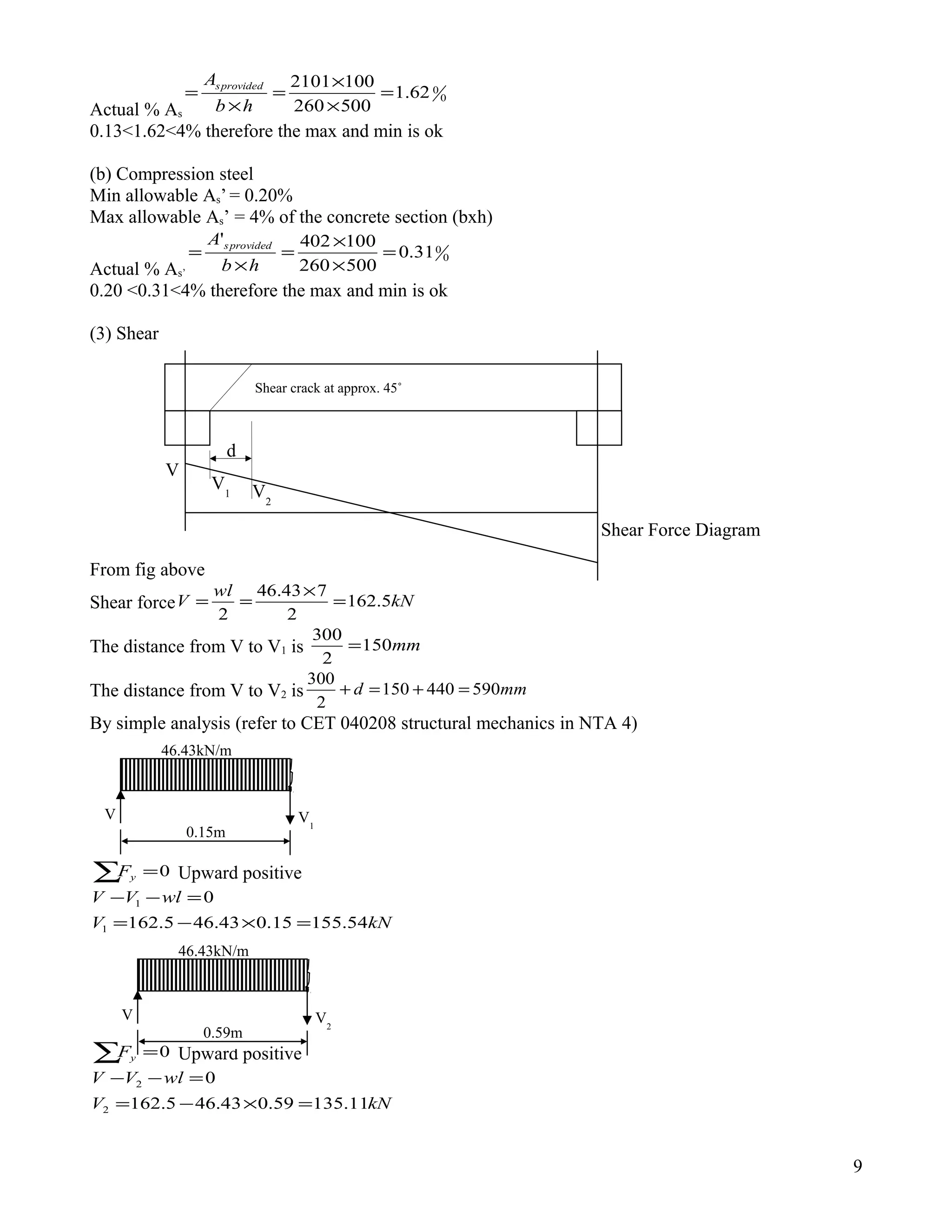
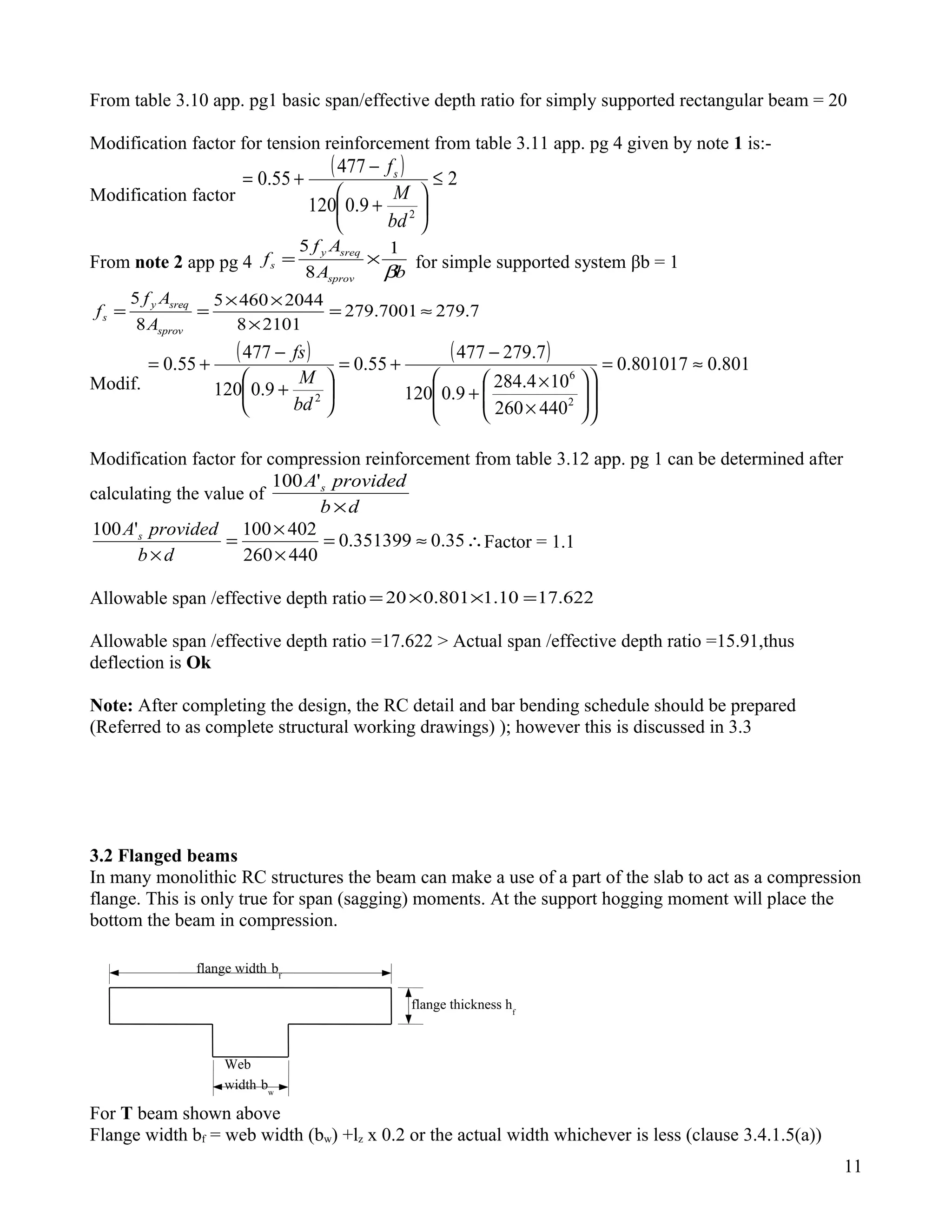
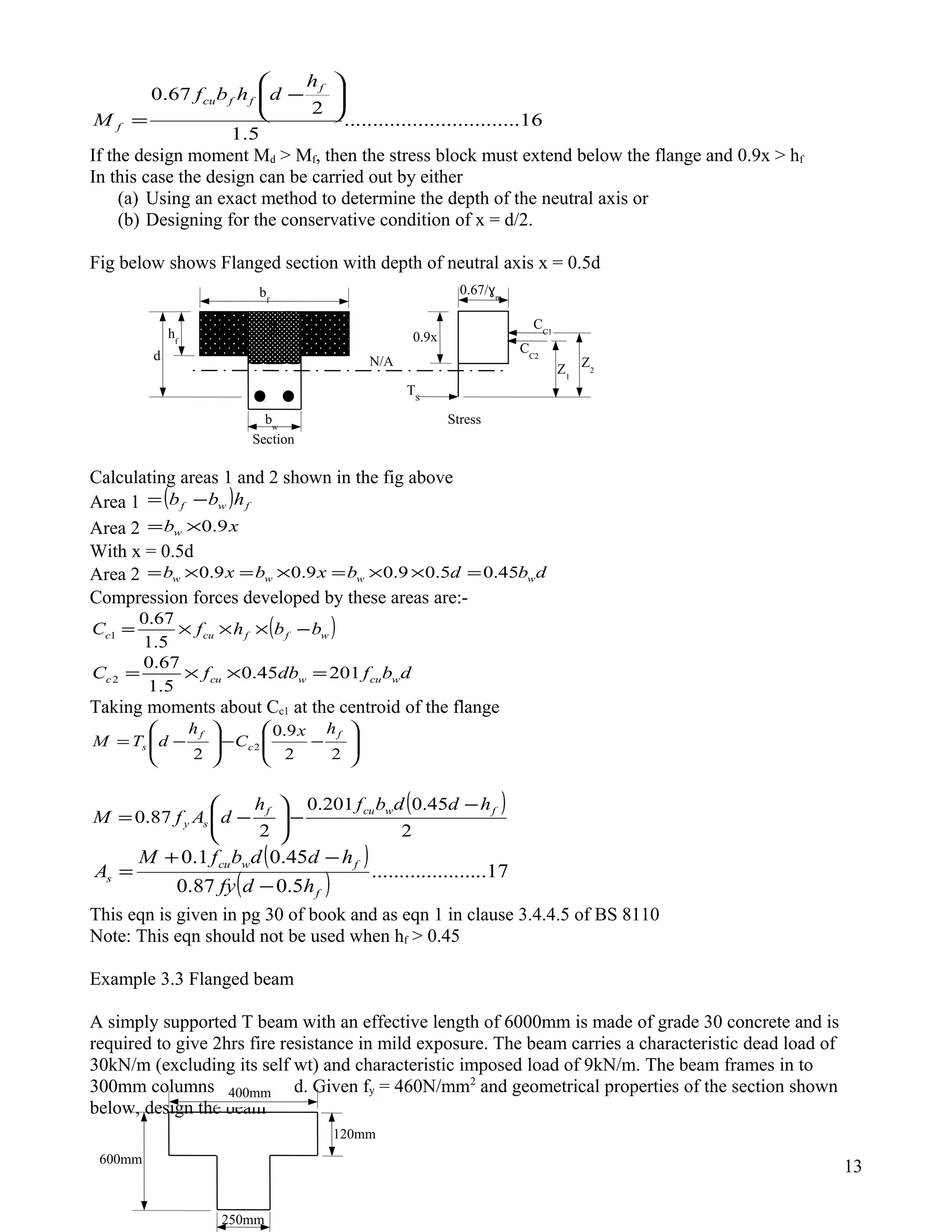
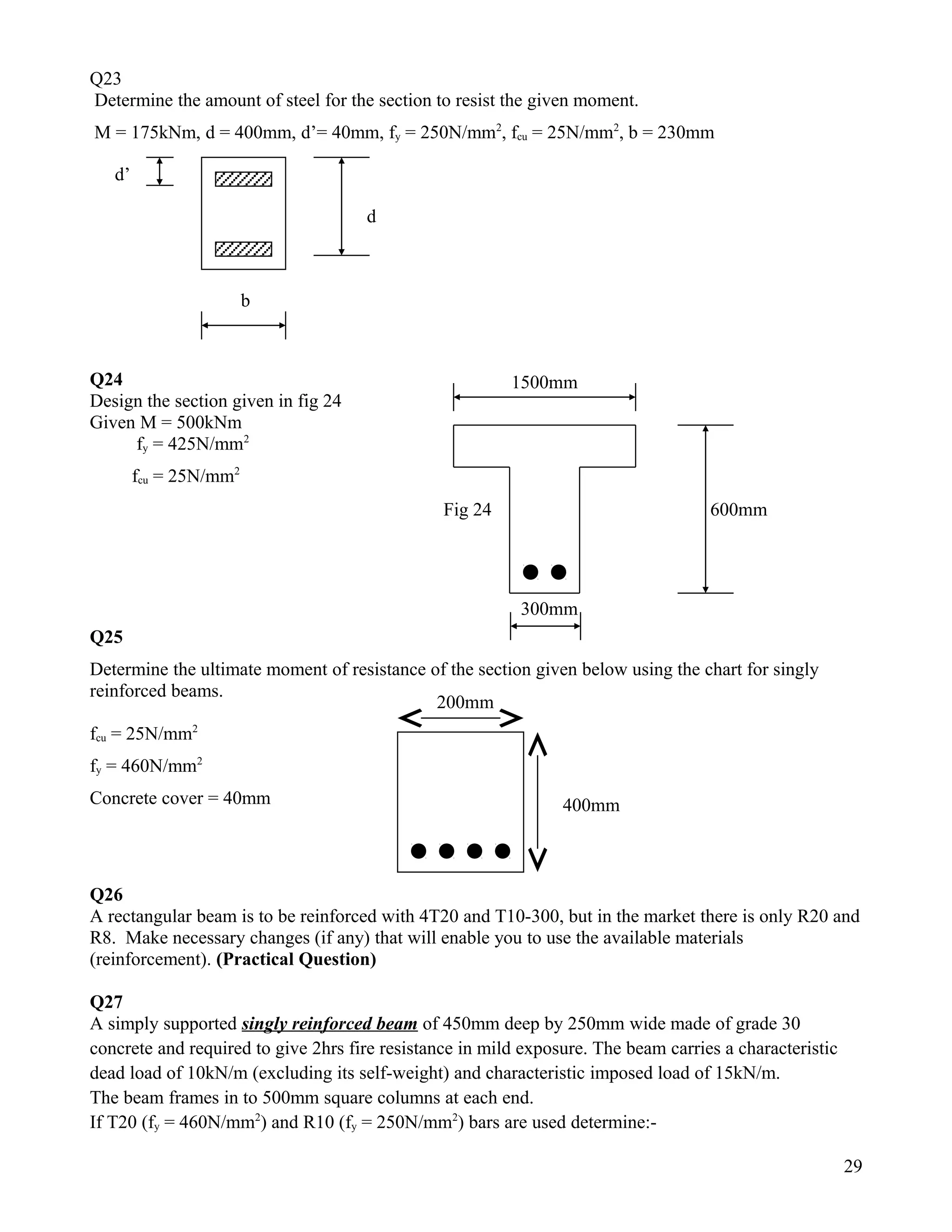
SlideShare a Scribd company logo
3.0 Design of Beams
3.1 Rectangular Beam
3.1.1 Singly Reinforced Beam
Example 3.1
Uniformly distributed characteristic load (udl)
Dead = 3.76 kN/m (excluding beam self weight)
Imposed = 10kN/m
Design the beam if fy = 460N/mm2
, fcu = 30N/mm2
and density of concrete ρconcrete = 24kN/m3
Soln
(1) Loading
Beam self-weight 54.44.1243.045.0 =×××=
Dead load 26.54.176.3 =×=
Imposed load 00.161610 =×=
Total design load mkN /8.25
(2) Bending
Bending moment
8
2
wl
M = ,l = effective span
Effective span (l) = Clear span + half support width at each end or Clear span + half effect depth at
each end whichever is less (BS 8110 Part1: 1985 clause 3.4.1.1)
7300400690070001006900 =+=+= or
kNmM 158
8
78.25 2
=
×
=
Using formulae, using table for z/d or using a design chart we can now calculate the area of steel.
(a) Formulae
11.0
30400300
10158
2
6
2
=
××
×
==
cufbd
M
k
















−+=
2
1
9.0
25.05.0
k
dz mm343
9.0
11.0
25.05.0400
2
1
=
















++=
2
6
1151
34346087.0
10158
87.0
mm
fy
M
As =
××
×
==
From the steel area table app pg 7
4T20 – B (4no high yield type two bars in the bottom of the beam)
(1260mm2
)
1
A
A
A-A
450
1006900100
300
400
Note: 106
changes moment from kNm to Nmm, in practice there has been tendency to use Y in place of
T and vice versa, however it should be noted that this is a mistake b’se Y is not identical to T. T has
higher bond strength than Y
Y stands for high yield deformed steel type one (square twisted bar) nowadays is obsolete (outdated)
T stands for high yield deformed steel type two (Ribbed bar) nowadays is extensively used
R stands for round mild steel.
(b) Tables
As above k = 0.11
z/d = 0.857 from table, Appendix page 7
343400857.0 =×=z
2
6
1151
34346087.0
10158
87.0
mm
zf
M
As
y
=
××
×
==
4T20 – B
(1260mm2
)
(iii) Chart
29.3
400300
10158
2
2
2
=
×
×
=
bd
M
98.0
100
=
bd
As
, From chart 2, appendix page 5
2
1176
100
40030098.0
mmAs =
××
=
4T20 – B
(1260mm2
)
The minimum and maximum areas of tension steel in a beam are given in clause 3.12.6.1 and table
3.27 of BS8110 see appendix pg 8
Min allowable = 0.13%
Max allowable = 4% of the concrete section (bxh)
Actual % As
0
093.0
450300
1001260
=
×
×
=
×
=
hb
A provideds
0.13<0.93<4% therefore the max and min is ok
3.1.1.2 Design in shear
The actual behaviuor of reinforced concrete under shear is very complex and still the subject of debate
among the researchers. However design techniques have been developed which work in practice.
To determine the shear force supported by the link reinforcement, consider the free body diagram to
one side of the crack shown in fig 3.1. Clearly only bars crossing the crack contribute.
2
sv
d
Fig 3.1 the free body to one side of an assumed 45˚ shear crack.
45˚
45˚
Number of bars
vs
d
=
Shear force supported by shear links/stirrups (Vs) sv
m
yv
v
A
f
s
d
××=
γ
Asv = Area of all legs of each shear link
Sv = spacing of links
fyv = characteristic strength of shear reinforcement
Converting the above force to an equivalent stress over the whole beam, vs, by dividing by the cross
sectional area of the concrete, bd
bd
A
f
sv
d
v sv
yv
s
1
15.1
×××=
For the beam to remain safe; the applied shear stress should be equal to the shear capacities contributed
by the steel and concrete.
Thus summing the contributions from the steel and concrete we have:-
v
svyv
c
cs
bs
Af
v
vvv
87.0
+=
+=
( )
yv
v
sv
f
bsvcv
A
87.0
−
=
In minor beams a minimum area of links that can support a shear stress of 0.4N/mm2
must be provided
throughout the whole beam.
Minimum
yv
v
sv
f
bs
A
87.0
4.0
=
Note: In practice, in the design of beam, after determining the required reinforcement for bending it is
then necessary to check the beam for shear.
First the shear forces (V) are calculated at the critical section. Then an average shear stress is
calculated by dividing the shear force (V) by the effective cross sectional area (bxd) of the beam
(clause 3.4.5.2). This stress is compared with the shear capacity of concrete and any excess stress is
catered for by providing shear links. Table 3.8 gives the requirement for shear reinforcement and table
3.9 gives the shear stress that the concrete can carry.
3
V2
V1
Shear Force Diagram
d
V
Shear crack at approx. 45˚
Fig 3.2
Shear stress must be checked as follows:-
Check 1 251
mm
Nv ≤ or cuf8.0 whichever is less. This check is sometimes referred to as check
for section dimensions for shear (clause 3.4.5.2).
Check 2 if 4.02 +≤ vcv , then nominal stirrups (links) of area
yv
v
sv
f
bs
A
87.0
4.0
=
Or if 4.02 +> cvv , then designed stirrups (links) of area
( )
yv
vc
sv
f
bsvv
A
87.0
2 −
=
Refer example 3.1
(3) Shear
From fig 3.2
Shear force kN
wl
V 3.90
2
78.25
2
=
×
==
The distance from V to the mid span is mm3500
2
7000
=
The distance from V1 to the mid span is mm3450503500 =−
The distance from V2 to the mid span is ( ) mm3050400503500 =+−
By similar triangles
kN
V
V
kN
V
V
VVV
69.78
3500
3.903050
3500
3050
01.89
3500
3.903450
3500
3450
305034503500
2
1
21
=
×
=
×
=
=
×
=
×
=
==
Shear stress
bd
forceshear
=
( )∴=×<=
×
×
= 382.4308.0742.0
400300
1001.89
2
3
1
mm
Nv Section dimensions are ok
2
3
2 656.0
400300
1069.78
mm
Nv =
×
×
=
Using table 3.9 for finding shear capacity of the concrete, the % area of tension steel effective at the
beam end must be known. In example 3.1 only two tension bars extend to the support. Thus area =
628mm2
for 2T20
%523.0
400300
628100100
=
×
×
=
bd
As
Then we need to interpolate in table 3.9 btn 0.5 and0.75%, the column for 400≥d
% 400≥d
at 0.50 vc = 0.50
4
at 0.75 vc = 0.57
at 0.523 vc =
( ) ( )
( ) 2506.0
50.075.0
5.0523.05.057.0
5.0
mm
N=
−
−×−
+
Note: Table 3.9 applies to a C25 concrete (see note2)
Thus the actual vc for C30 (vc30) 2
3
1
3
1
538.0
25
30
506.0
25
506.0
mm
Nfcu
=





×=





×=
( )∴=+<= 22 930.004656.0
mm
Nvcv Nominal stirrups (links) of area
yv
v
sv
f
bs
A
87.0
4.0
=
But the maximum spacing of link (svmax) is 0.75d (see clause 3.4.5.5 of BS 8110)
mmdsv 30040075.075.0 =×==
2
1665.165
25087.0
3003004.0
87.0
4.0
mm
f
bs
A
yv
v
sv ≈=
×
××
==
Note: each stirrup passes one side of the beam and back down the other. Its area thus counts twice.
By reference to steel area table on pg 7 of the appendix the likely areas are:-
2R8 = 101mm2
, 2R10 = 157mm2
, 2R12 = 226mm2
. Here R10 will be used because R8 will give more
stirrups while R12 will give the spacing greater than the recommended.
If R10 are used will have to be at closer center than 300mm.
Thus mmsv 284
166
157300
=
×
= maximum centers
It is normal to space stirrups (links) at centers of multiples of 25, the spacing will be 275mm
R10-275
2Nominal (not designed) bars are to be added at the beam top to support stirrups (links). Their
diameter is normally half diameter of the tension steel but in the order of 20,16 and 12.
Total number of stirrups (links). 278.261
275
7100
1 ≈=+=+=
Spacing
beamtheofspanoverall
3.1.1.3 Design in deflection
After determining load, bending and shear finally we have to check for the beam in deflection. In
monolithic concrete frames actual deflection is not calculated b’se is inaccurate and time consuming.
Instead we have to compare the actual span /effective depth ratio of the beam with the allowable
span /effective depth ratio defined in table3.10, 3.11 and 3.12(for doubly reinforced beam)
Refer example 3.1
Actual span /effective depth ratio 5.17
400
7000
===
depthEffective
spanEffective
Allowable span /effective depth ratio = Factor from table3.10 x Factor from table 3.11
From table 3.10 app. pg1 basic span/effective depth ratio for simply supported rectangular beam = 20
Modification factor for tension reinforcement from table 3.11 app. pg 4 given by note 1 is:-
Modification factor
( ) 2
9.0120
477
55.0
2
≤






+
−
+=
bd
M
fs
From note 2 app pg 4
bA
Af
f
sprov
sreqy
s
β
1
8
5
×= for simple supported system βb = 1
5
63.2626289683.262
12608
11514605
8
5
≈=
×
××
==
sprov
sreqy
s
A
Af
f
Modif.
( ) ( ) 976.097618.0
400300
10158
9.0120
63.262477
55.0
9.0120
477
55.0
2
6
2
≈=














×
×
+
−
+=






+
−
+=
bd
M
fs
Allowable span /effective depth ratio 52.19976.020 =×=
Allowable span /effective depth ratio =19.52 > Actual span /effective depth ratio =17.5,thus deflection
is Ok
Note: After completing the design, the RC detail and bar bending schedule should be prepared
(Referred to as complete structural working drawings). ); however this is discussed in 3.3
3.1.2 Doubly reinforced beam
When M>0.156bd2
fcu the design ultimate moment M exceeds the moment of resistance of the concrete,
the compression reinforcement is required. For this condition the depth of neutral axis, dx 5.0 , the
maximum value allowed by the code in order to insure a tension failure with a ductile section
Therefore eqn 5 becomes
6
d
d
d
x
dz 775.0
2
5.09.0
2
9.0
=
×
−=−=
Cc = Compression force in concrete
Cs = Compression force in steel
Ts = Tensile force in steel
As’ = Area of Compression steel
As = Area of tension steel
For equilibrium of the section above
Ts =Cc+Cs
'87.0
5.1
9.067.0
87.0 s
cu
sy fyA
xbf
Af +
××
=
with
2
d
x =
11........................'87.0201.087.0 sycusy AfbdfAf +=
Taking the moment about the tension steel As
( )
)'('87.0156.0
12.).........'('87.0775.0201.0
'
2
ddfyAfbd
ddAfdbdf
ddCzCM
scu
sycu
sc
−+=
−+×=
−+×=
13.............................................
)'(87.0
156.0
'
2
ddf
bdfM
A
y
cu
s
−
−
=
But cufkbdM 2
=
( ) 14.............................................
)'(87.0
156.0
'
2
ddf
bdfK
A
y
cu
s
−
−
=
Multiplying both sides of eqn 11 by z = 0.775d
15............................................'
775.087.0
156.0
.
2
s
y
cu
s A
df
bdf
A +
×
=
Example 3.2 Doubly reinforced
A simply supported beam of effective span 7000mm is 500mm deep by 260mm wide. It is made of
grade 30 concrete and is required to give 2hrs fire resistance in mild exposure. The beam carries a
7
Z=lever arm
Cs
0.67fcu
/ɣm
d’
b
Beam
section
stress blockx=0.5d
0.9x
d
N/A
Fig 3.3 beam section with compression reinforcement
As
’
Ts
Cc
As
characteristic dead load of 12.9kN/m in addition to its self-weight and characteristic imposed load of
15kN/m.
The beam frames in to 300mm
at each end.
If fy = 460N/mm2
design the beam
(1) Loading
Self wt of the beam 37.44.12426.05.0 =×××=
Dead load 06.184.19.12 =×=
Imposed load 00.246.115 =×=
Total design load
m
kN43.46=
(2)Bending
Bending moment kNm
wl
M 4.284
8
743.46
8
22
=
×
==
Cover: exposure 25mm table 3.4
Fire 40mm table 3.5
Effective depth d = h- (cover + dia of link (stirrup) +0.5dia of tension steel)
Assume T20 and R10 will be used as tension and shear link resp.
Effective depth mmd 440
2
20
1040500 =





++−=
∴>=
××
×
== 156.0188.0
30440260
104.284
2
6
2
cufbd
M
k Doubly reinforced
d’= cover +stirrup dia +0.5dia of compression bar
Assume compression bar to be T20
mmd 60
2
20
1040' =++=
( )
( )
( )
( )
2
22
31875.317
6044046087.0
30260440156.0188.0
'87.0
156.0
' mm
ddf
fbdK
A
y
cu
s ≈=
−××
×××−
=
−
−
=
2
22
20443181726318
440775.046087.0
30260440156.0
'
775.087.0
156.0
mmA
df
fbd
A s
y
cu
s =+=+
×××
×××
=+
×
=
From steel area table app pg 7
2T32+1T25 – B
(2101mm2
)
2T16-T
(402mm2
)
Check for maximum and minimum allowable
The minimum and maximum areas of tension and compression steel in a beam are given in table 3.27
(appendix pg 8) and clause 3.12.6.1 of BS8110
(a) Tension steel
Min allowable As = 0.13%
Max allowable As = 4% of the concrete section (bxh)
8
Actual % As
0
062.1
500260
1002101
=
×
×
=
×
=
hb
A provideds
0.13<1.62<4% therefore the max and min is ok
(b) Compression steel
Min allowable As’ = 0.20%
Max allowable As’ = 4% of the concrete section (bxh)
Actual % As’
0
031.0
500260
100402'
=
×
×
=
×
=
hb
A provideds
0.20 <0.31<4% therefore the max and min is ok
(3) Shear
From fig above
Shear force kN
wl
V 5.162
2
743.46
2
=
×
==
The distance from V to V1 is mm150
2
300
=
The distance from V to V2 is mmd 590440150
2
300
=+=+
By simple analysis (refer to CET 040208 structural mechanics in NTA 4)
∑ =0yF Upward positive
kNV
wlVV
54.15515.043.465.162
0
1
1
=×−=
=−−
∑ =0yF Upward positive
kNV
wlVV
11.13559.043.465.162
0
2
2
=×−=
=−−
9
V V1
0.15m
46.43kN/m
V V2
0.59m
46.43kN/m
V2
V1
Shear Force Diagram
d
V
Shear crack at approx. 45˚
Shear stress
bd
forceshear
=
( )∴=×<=
×
×
= 382.4308.036.1
440260
1054.155
2
3
1
mm
Nv Section dimensions are ok
2
3
2 18.1
440260
1011.135
mm
Nv =
×
×
= This must be compared with vc
Using table 3.9 for finding shear capacity of the concrete, the % area of tension steel effective at the
beam end must be known. In this example only two tension bars extend to the support. Thus area =
1610mm2
for 2T32
%41.1
440260
1610100100
=
×
×
=
bd
As
Then we need to interpolate in table 3.9 btn 1.0 %and1.5%, the column for 400≥d
% 400≥d
at 1.0 vc = 0.63
at 1.5 vc = 0.72
at 1.41 vc =
( ) ( )
( ) 2704.0
15.1
0.141.163.072.0
63.0
mm
N=
−
−×−
+
Note: Table 3.9 applies to a C25 concrete (see note2)
Thus the actual vc for C30 (vc30) 2
3
1
3
1
748.0
25
30
704.0
25
704.0
mm
Nfcu
=





×=





×=
( )∴=+>= 22 148.14.018.1
mm
Nvcv designed stirrups (links) of area
( )
yv
vc
sv
f
bsvv
A
87.0
2 −
=
But the maximum spacing of link (svmax) is 0.75d (see clause 3.4.5.5 of BS 8110)
mmdsv 33044075.075.0 =×==
( ) ( ) 22
17041.170
25087.0
330260748.018.1
87.0
mm
f
bsvv
A
yv
vc
sv ≈=
×
××−
=
−
=
By reference to steel area table on pg 7 of the appendix the likely areas are:-
2R8 = 101mm2
, 2R10 = 157mm2
, 2R12 = 226mm2
. Here R10 will be used because R8 will give more
stirrups while R12 will give the spacing greater than the recommended.
Thus mmsv 30576.304
170
157330
≈=
×
= maximum centers
It is normal to space stirrups (links) at centers of multiples of 25, the spacing will be 275mm
R10-300
Total number of stirrups (links).
( ) 2333.231
300
3007000
1
2sup.
≈=+
−
=+
×−
=
Spacing
widthporthalfbeamtheofspaneff
(4) Deflection
Actual span /effective depth ratio 91.1590909.15
440
7000
≈===
depthEffective
spanEffective
Allowable span /effective depth ratio = Factor from table3.10 x Factor from table 3.11x Factor from
table3.12
10
From table 3.10 app. pg1 basic span/effective depth ratio for simply supported rectangular beam = 20
Modification factor for tension reinforcement from table 3.11 app. pg 4 given by note 1 is:-
Modification factor
( ) 2
9.0120
477
55.0
2
≤






+
−
+=
bd
M
fs
From note 2 app pg 4
bA
Af
f
sprov
sreqy
s
β
1
8
5
×= for simple supported system βb = 1
7.2797001.279
21018
20444605
8
5
≈=
×
××
==
sprov
sreqy
s
A
Af
f
Modif.
( ) ( ) 801.0801017.0
440260
104.284
9.0120
7.279477
55.0
9.0120
477
55.0
2
6
2
≈=














×
×
+
−
+=






+
−
+=
bd
M
fs
Modification factor for compression reinforcement from table 3.12 app. pg 1 can be determined after
calculating the value of
db
providedA s
×
'100
∴≈=
×
×
=
×
35.0351399.0
440260
402100'100
db
providedA s
Factor = 1.1
Allowable span /effective depth ratio 622.1710.1801.020 =××=
Allowable span /effective depth ratio =17.622 > Actual span /effective depth ratio =15.91,thus
deflection is Ok
Note: After completing the design, the RC detail and bar bending schedule should be prepared
(Referred to as complete structural working drawings) ); however this is discussed in 3.3
3.2 Flanged beams
In many monolithic RC structures the beam can make a use of a part of the slab to act as a compression
flange. This is only true for span (sagging) moments. At the support hogging moment will place the
bottom the beam in compression.
For T beam shown above
Flange width bf = web width (bw) +lz x 0.2 or the actual width whichever is less (clause 3.4.1.5(a))
11
flange width bf
flange thickness hf
Web
width bw
For L beam shown above
Flange width bf = web width (bw) +lz x 0.1 or the actual width whichever is less (clause 3.4.1.5(b))
Where
lz is the distance btn points of zero moment (which, for a continuous beam, may be taken as 0.7 times
the effect span)
For T-sections and L sections which have their flanges in compression can both be designed or
analysed in a similar manner, and the eqns which are derived can be applied to either type of cross
section. As the flanges generally provide a large compression area, it is usually unnecessary to
consider the case where compression steel is required.
For the singly reinforced section it is necessary to consider two separate cases:-
(a) The stress block lies within the compression flange
(b) The stress block extends below the flange
3.2.1 Flanged section with the depth of the stress block lies within the flange 0.9x < hf
The fig above shows the T section, stress block within the flange 0.9x < hf
For this depth of stress lock, the beam can be considered as an equivalent rectangular section of
breadth bf equal to the flange width. This is because the non- rectangular section below the neutral axis
is in tension and is, therefore considered to be cracked and in active.
Therefore
cuf fdb
M
k 2
=
2
9.0 x
dz −=
zf
M
A
y
s
87.0
=
3.2.2 Flanged section with the depth of the stress block extending below the flange 0.9x > hf
An alternative procedure to check if he depth of the stress block extends below the flange, is to
calculate the moment of resistance, Mf, of the flange (section) with 0.9x = hf, the depth of the flange.
Moment of resistance, Mf, of the flange is
12
flange width bf
flange thickness hf
Web
width bw
TS
CC
Section
Stress
Z
0.67/ɣm
0.9x
N/A
d
bf
hf
bw
16...............................
5.1
2
67.0 





−
=
f
ffcu
f
h
dhbf
M
If the design moment Md > Mf, then the stress block must extend below the flange and 0.9x > hf
In this case the design can be carried out by either
(a) Using an exact method to determine the depth of the neutral axis or
(b) Designing for the conservative condition of x = d/2.
Fig below shows Flanged section with depth of neutral axis x = 0.5d
Calculating areas 1 and 2 shown in the fig above
Area 1 ( ) fwf hbb −=
Area 2 xbw 9.0×=
With x = 0.5d
Area 2 dbdbxbxb wwww 45.05.09.09.09.0 =××=×=×=
Compression forces developed by these areas are:-
( )wffcuc bbhfC −×××=
5.1
67.0
1
dbfdbfC wcuwcuc 20145.0
5.1
67.0
2 =××=
Taking moments about Cc1 at the centroid of the flange








−−







−=
22
9.0
2
2
f
c
f
s
hx
C
h
dTM
( )
2
45.0201.0
2
87.0 fwcuf
sy
hddbfh
dAfM
−
−





−=
( )
( ) 17.....................
5.087.0
45.01.0
f
fwcu
s
hdfy
hddbfM
A
−
−+
=
This eqn is given in pg 30 of book and as eqn 1 in clause 3.4.4.5 of BS 8110
Note: This eqn should not be used when hf > 0.45
Example 3.3 Flanged beam
A simply supported T beam with an effective length of 6000mm is made of grade 30 concrete and is
required to give 2hrs fire resistance in mild exposure. The beam carries a characteristic dead load of
30kN/m (excluding its self wt) and characteristic imposed load of 9kN/m. The beam frames in to
300mm columns at each end. Given fy = 460N/mm2
and geometrical properties of the section shown
below, design the beam
13
Z1
2
CC2
TS
CC1
Section
Stress
Z2
0.67/ɣm
0.9x
N/Ad
bf
hf
bw
11
600mm
400mm
120mm
250mm
(1) Loading
bf = bw + 0.2lz or the given value whichever is less
mmbf 14502.06000250 =×+= or 400mm
bf = 400mm
Self-wt ( ) 6.54.12448.025.04.012.0 =×××+×=
Dead load 424.130 =×=
Live load 4.144.19 =×=
Ultimate load
m
kN62=
(2) Bending
Bending moment kNm
wl
M 279
8
662
8
22
=
×
==
Cover: exposure 25mm table 3.4
Fire 40mm table 3.5
Effective depth d = h- (cover + dia of link (stirrup) +0.5dia of tension steel)
Assume T20 and R10 will be used as tension and shear link resp.
Effective depth mmd 540
2
20
1040600 =





++−=
079.00793.0
30440400
10279
2
6
2
≈=
××
×
==
cuf fdb
M
k
z/d = 0.903(from Lever Arm Table
z = 0.903d
From eqn 5 xdz 9.05.0 ×−=
( ) mmdddx 10576.104540194.0194.0903.029.0 ≈=×==−=
0.9x = 105<hf = 120∴the stress block lies within the flange.
Alternatively we can check if the stress block lies within the flange by comparing the moment of
resistance Mf of the flange and the design moment Md. IF Mf > Md, then stress block lies within the
flange, otherwise the stress block extends below the flange
( ) kNm
h
dhbf
M
f
ffcu
f 309
5.1
101205.05401204003067.0
5.1
2
67.0 6
=
××−××××
=






−
=
−
Mf = 309>Md=279∴the stress block lies within the flange.
2
6
1430702277.1429
540903.046087.0
10279
87.0
mm
zf
M
A
y
s ≈=
×××
×
==
From steel area table app pg 7
3T25 – B
(1470mm2
)
14
Check for maximum and minimum allowable
The minimum and maximum areas of tension and compression steel in a beam are given in table 3.27
(appendix pg 8) and clause 3.12.6.1 of BS8110
4.0625.0
400
250
>==
f
w
b
b
Therefore max and min As are as indicated below
Min allowable As = 0.13%
Max allowable As = 4% of the concrete section (bxh)
Actual % As
0
098.0
600250
1001470
=
×
×
=
×
=
hb
A
w
provideds
0.13<0.98<4% therefore the max and min is ok
(3) Shear
From fig above
Shear force kN
wl
V 186
2
662
2
=
×
==
The distance from V to V1 is mm150
2
300
=
The distance from V to V2 is mmd 690540150
2
300
=+=+
By simple analysis (refer to CET 040208 structural mechanics in NTA 4)
∑ =0yF Upward positive
kNV
wlVV
7.17615.062186
0
1
1
=×−=
=−−
∑ =0yF Upward positive
15
V V1
0.15m
62kN/m
V V2
0.69m
62kN/m
V2
V1
Shear Force Diagram
d
V
Shear crack at approx. 45˚
kNV
wlVV
22.14369.062186
0
2
2
=×−=
=−−
Shear stress
bd
forceshear
=
( )∴=×<=
×
×
= 382.4308.031.1
540250
107.176
2
3
1
mm
Nv Section dimensions are ok
2
3
2 06.1
540250
1022.143
mm
Nv =
×
×
= This must be compared with vc
Using table 3.9 for finding shear capacity of the concrete, the % area of tension steel effective at the
beam end must be known. In this example only two tension bars extend to the support. Thus area =
982mm2
for 2T25
73.07274.0
540250
982100100
≈=
×
×
=
db
As
w
Then we need to interpolate in table 3.9 btn 0.5 and 0.75% the column for 400≥d
% 400≥d
at 0.5 vc = 0.5
at 0.75 vc = 0.57
at 1.41 vc =
( ) ( )
( ) 2564.0
50.075.0
5.073.05.057.0
5.0
mm
N=
−
−×−
+
Note: Table 3.9 applies to a C25 concrete (see note2)
Thus the actual vc for C30 (vc30) 2
3
1
3
1
60.0
25
30
564.0
25
564.0
mm
Nfcu
=





×=





×=
( )∴=+>= 22 0.14.006.1
mm
Nvcv Designed stirrups (links) of area
( )
yv
vc
sv
f
bsvv
A
87.0
2 −
=
The maximum spacing of link (svmax) is 0.75d (see clause 3.4.5.5 of BS 8110)
mmdsv 40554075.075.0 =×==
( ) ( ) 22
214137931.214
25087.0
4052506.006.1
87.0
mm
f
bsvv
A
yv
vc
sv ≈=
×
××−
=
−
=
It is normal to space stirrups (links) at centers of multiples of 25, the spacing will be 400mm
R12-400
2Nominal (not designed) bars are to be added at the beam top to support stirrups (links). Their
diameter is normally half diameter of the tension steel but in the order of 20,16 and 12.
Total number of stirrups (links).
( ) 151
400
3006000
1
2sup.
=+
−
=+
×−
=
Spacing
widthporthalfbeamtheofspaneff
(4) Deflection
Actual span /effective depth ratio 11.11
540
6000
===
depthEffective
spanEffective
Allowable span /effective depth ratio = Factor from table3.10 x Factor from table 3.11x Factor from
table3.12
16
From table 3.10 app. pg1 basic span/effective depth ratio for simply supported flanged beam
3.0625.0
400
250
>==
b
bw
thus linear interpolation should be applied (clause 3.4.6.3)
3.0625.01 ===
b
b
b
b
b
b www
20 a 16
( )( ) 85.17857143.17
3.01
3.0625.01620
16 ≈=
−
−−
+=a
Modification factor for tension reinforcement from table 3.11 app. pg 4 given by note 1 is:-
Modification factor
( ) 2
9.0120
477
55.0
2
≤






+
−
+=
bd
M
fs
From note 2 app pg 4
bA
Af
f
sprov
sreqy
s
β
1
8
5
×= for simple supported system βb = 1
26.2802636.280
14708
14334605
8
5
≈=
×
××
==
sprov
sreqy
s
A
Af
f
Modif.
( ) ( ) 05.1
540400
10279
9.0120
26.280477
55.0
9.0120
477
55.0
2
6
2
=














×
×
+
−
+=






+
−
+=
bd
M
fs
Allowable span /effective depth ratio 74.187425.1805.185.17 ≈=×=
Allowable span /effective depth ratio =18.753 > Actual span /effective depth ratio =11.11,thus
deflection is Ok
Note: After completing the design, the RC detail and bar bending schedule should be prepared
(Referred to as complete structural working drawings); however this is discussed in 3.3
17
3.3 Preparation of structural drawings.
3.3.1 Introduction
To be able to prepare detailed structural drawings we need to know the following first:-
3.3.2 Anchorage length
The reinforcement bar subjected to tension must be properly anchored otherwise may be pulled out of
the concrete.
The anchorage length depends on the bond between the bar and the concrete, and the area of contact.
Let,
L = be the minimum anchorage length to prevent pull out
F = the nominal diameter
fbu = ultimate anchorage bond stress
fs = direct compressive/tensile stress in the bar
F = applied tensile force
Consider the forces in the bar
Tensile pull out force F = Bar’s cross- sectional area × direct stress
sss ffAF ×=×=
4
2
πφ
Anchorage force = Contact area × anchorage bond stress
18
L
anchorage bond stress fbu
F
F
bufL πφ×=
In order this system to remain in equilibrium these two forces should be equal
sbu ffL
4
2
πφ
πφ =
Anchorage length L =
bu
s
f
f
4
φ
but fs = 0.87fy, the ultimate tensile or compressive stress
Anchorage length L =
bu
y
f
f
4
87.0 φ
The design ultimate anchorage bond stress, fbu is given by the equation
cubu ff β=
Therefore the Anchorage L =
cu
y
f
f
β
φ
4
)87.0(
bis the bond coefficient which depends on bar type and the type of force the bar is subjected to.
The values of b are given in table 3.28 of BS 8110.
Table 3.28 Values of bond coefficient b
Bar type Bar in tension Bar in compression
Plain bars 0.28 0.35
Type1:deformed bar (Y) 0.40 0.50
Type2:deformed bar (T) 0.50 0.63
Fabric 0.65 0.81
(Note: Type 2 (T) ribbed, Type 1(Y) square twisted inferior bond characteristic)
Example 3.4
Determine the length of tension anchorage required for the 25mm diameter plain mild steel
reinforcement (R25) in the cantilever beam made of grade 30 concrete
Solution
25.13028.0
mm
Nff cubu === β
19
Anchorage Length L
Effective span
mm
f
f
L
bu
y
25.90625
5.14
25087.0
4
87.0
=×
×
×
==
φ
Say 910mm
3.3.2.1 Anchorage of bars at simply supported end of a member (clause 3.12.9.4)
At simply supported end of a member, each tension bar should be anchored by one of the following
(a) An effective anchorage length equivalent to 12 times the bar size beyond the centre line of the
support; no bend or hook should begin before the centre of the support.
(b) An effective anchorage length equivalent to 12 times the bar size plus d/2 from the face of the
support, where d is the effective depth of member; no bend or hook should begin before d/2
from the face of the of the support.
(c) For slabs, if the design ultimate shear stress at the face of the support is less than the
appropriate value, vc, recommended in (clause 3.4.5), a straight length of bar beyond the centre
line of the support equal to either one third of the support width or 30mm, whichever is the
greater.
3.3.2.2 Anchorage of links (clause 3.12.8.6)
A link may be considered to be fully anchored if it satisfies the following:
(a) It passes around another bar of at least its own size, through an angle of 90°, and continues
beyond for a minimum length of eight(8) times its own size; or
(b) It passes around another bar of at least its own size, through an angle of 180°, and continues
beyond for a minimum length of four(4) times its own size;
3.3.3 Laps
Lapping of reinforcement is often necessary to transfer the forces from one bar to another. They should
be placed, if possible, away from points of high stress and should preferably be staggered (clause
3.12.8.9)
3.3.3.1 Minimum laps (clause 3.12.8.11)
The minimum lap length for bar reinforcement should be not less than 15 times the bar size or 300mm,
whichever is greater, and for fabric reinforcement should be not less than 250mm.
3.3.3.2 Tension laps (clause 3.12.8.13)
The tension lap length should be at least equal to the design tension anchorage length (see 2.2 above)
necessary to develop the required stress in the reinforcement. Lap length for unequal size bars (or
wires in fabric) may be based upon the smaller bar. The following provisions also apply:
(a) Where a lap occurs at the top of a section as cast and the minimum cover to either is less than
twice the size of the lapped reinforcement, the lap length should be increased by a factor of 1.4;
20
(b) Where a lap occurs at the the corner of section and the minimum cover to either face is less
than twice the size of the lapped reinforcement or, whwre the clear distance between adjacent
laps is less than 75mm or six times the size of the lapped reinforcement, whichever is the
greater, lap length should be increased by a factor of 1.4;
(c) In cases where both conditions (a) and (b) apply, the lap length should be increased by a factor
of 2;
3.3.3.3 Compression laps (clause 3.12.8.15)
The compression lap length should be at least 25% greater than compression anchorage length
(see 3.3.3.2 above) necessary to develop the required stress in the reinforcement. Lap length for
unequal size bars (or wires in fabric) may be based upon the smaller bar.
3.3.4 Curtailment of reinforcement
Curtailment of reinforcement in reinforced concrete structural working drawing in accordance with the
standards is necessary in order to avoid providing redundant reinforcement.
3.3.4.1 Curtailment of reinforcement in beams (clause 3.12.10.2)
The simplified curtailment rules illustrated in figure 3.24 on app pg 9 of book1 design tables to BS
8110 may be used for beams in the following circumstances.
(a) The beams are designed for predominantly uniformly distributed loads.
(b) In the case of continuous beams, the spans are approximately equal.
After being conversant with literature above; the complete structural drawings (ga, rc details and bar
bending schedules) are prepared as we shall see/discuss in the class.
21
Tutorials BEAMS
Q1
For the cantilever “T” – beam of 4m length find the maximum design load w, if the reinforcement
consist of 2 high yield steel bars of 20mm dia. (As = 6.28 cm2
), fy = 460N/mm2
and the concrete is
grade 30, fcu = 30N/mm2
. The beam has a cross section as shown in Fig. 1
w=? 400mm
100
4000
d =500
FIG1 200
Q2
An overhanging reinforced concrete beam carries a uniformly distributed load of 5kN/m and
concentrated loads of 20kN at the ends of the beam (Fig.2).
20kN 20kN
5kN/m
22
2m A 6m B 2m
FIG 2
(i) Determine the support reactions and the maximum bending moment. Draw the bending
moment diagram.
(ii) Sketch the pattern of main reinforcement for the beam.
(iii) Using a rectangular stress block define the depth of compressive zone x and the ultimate
moment of resistance Mu if the effective depth of the beam 400mm, width of section
200mm, cross – sectional area of bars 628mm2
. Given the characteristics strengths are fy =
425N/mm2
for the reinforcement, and fcu = 25N/mm2
for the concrete. Check the resistance
of the beam.
Q3
A simply supported T-beam of 6m length carries a uniformly distributed load of 30kN/m (including
self weight). The main geometrical characteristics of the cross-section are as shown in figure1. The
materials to be used are grade 30 concrete, fcu =30N/mm2
and high yield steel of strength fy
=425N/mm2
. Determine the area of steel required at mid-span, assuming the effective depth of the
beam is 0.9h.
23
FIG.1 ALL DIMENSIONS ARE mm
Q4
By mistake a contractor provided 2Y32 and 1Y25 tension steel to a rectangular beam. His poor
workmanship produced concrete of strength 28N/mm2
while the dimensions of the beam section were
as per design which is b/d = 300/700mm. If the characteristic strength of the steel is fy = 410/mm2
,use a
simplified rectangular stress block to calculate the maximum bending moment which the beam can
safely support.
Q5
Shown in the figure below is a rectangular section of a beam and a rectangular stress block
distribution. Obtain the expression for the maximum ultimate resistance for the section.
Q6
a) A rectangular beam b/d = 300mm/700mm is to resist a bending moment of 625kNm. Using a
simplified rectangular stress block, calculate the amount of reinforcement required given that fcu
= 30N/mm2
and fy = 410N/mm2
.
b) Determine the amount of reinforcement using the design chart. Compare the two results.
Q7
Two beam sections are shown below, one being rectangular and the other flanged section.
Both are used to carry a moment of 615kNm. Compare the areas of steel required for each case and
hence give the advantages of flanged beams over rectangular ones.
24
All dimensions are in mm.
For both cases, fcu = 30N/mm2
, fy = 410N/mm2
, d = 618mm
d1
= 60mm (embedment of compression reinforcement)
Use 0.72fy for compression steel and 0.87fy for the tension steel.
Q8
A reinforced concrete beam cantilivering on one end carries a uniformly distributed load of 30kN/m as
shown in figure1. The breadth and effective depth of the beam are 300mm and 400mm, respectively.
Given the characteristic strength as fy =460N/mm2
for reinforcement and fcu = 30N/mm2
for concrete,
determine:
(a) the maximum bending moments (sagging and hogging).Draw Bending moment
diagram.
(b) the reinforcement for the beam.
(c) the scheme of reinforcements.
Fig. 1.
Q9
Determine the maximum moment of resistance at ultimate limit state and the of steel required for a
rectangular beam given that b = 300mm, d = 500mm, fcu = 25N/mm2
, fy = 410N/mm2
.
Q10
A simply supported concrete lintel of effective span 4.5m is 450mm deep by 300mm wide.It is made
of grade 30 concrete and is required give a 1 hour fire resistance in mild exposure.
The lintel carries an imposed load of 15kN/mand dead load including self weight of 20kN/m. If
bearing distance of the lintelis 150mmeach end, determine:
(a)tensile reinforcement
(b)shea reinforcement.
Use fy = 460N/mm2
,fyv = 250N/mm2
and diameter of the tensile steel reinforcement as 20mm.
Q11
(b) Determine the ultimate moment of resistance of the tee section shown in figure 1 if characteristic
material strengths are fy = 460N/mm2
, fcu = 30N/mm2
. Asumme s =hf.
25
Figure 1
Q12
(b) A simply supported concrete beam of cross- section 250×450mm spans 3.0m. The dead load
including self-weight of the beam is 8.0KN/m and the live load is 6.0KN/m. The material of
construction are fcu = 30N/mm2
, and fy = 460N/mm2
.
Determine: -
(i) Ultimate design load
(ii) The maximum flexural bending moment at mid span
(iii) The area of steel at mid span if the effective depth of the beam is 400mm. Use design chart.
Q13
A simply supported beam of the cross-section 300×500mm is doubly reinforced as shown in
fig.1.Find the area of steel required in tension (As) and the area of steel in compression As’ in
order to resist a dead load of 20KN/m and an imposed load of 20KN/m excluding self weight. Take
the effective span as 6.92m, fcu = 40N/mm2
& fy = 460N/mm2
.
Fig.1
Q14
An RC beam of uniform cross-section is to carry an ultimate design load W = 10kN/m and a midspan
point load of P = 40kN.The beam is freely supported with effective span of 6.0m.
(a) Determine the amount reinforcement required if b = 200mm, d = 350mm, fcu = 30N/mm2
and fy
= 460N/mm2
(b) Check for deflection if the service stress is given as 288N/mm2
Q15
A simply supported rectangular beam carries characteristic dead load gk of 10kN/m including the beam
self weight. Characteristic imposed load carried by beam qk is 12kN/m.the beam has a breadth of
230mm and the effective depth d of 450mm. If the material strength are fcu = 30N/mm2
and fy =
460N/mm2
,
(a) Will the section be singly or doubly reinforced?
(b) Determine the amount of reinforcing steel bars required.
(c) Check the serviceability limit state of deflection for the beam.
26
Q16
A student working at a construction site on an industrial training investigated a beam whose section is
shown in figure Q3 below. The beam has a span of 6.0m and can be considered to be simply supported.
If the material strengths are fcu = 25N/mm2
and fy = 460N/mm2
,
(a) determine the design load
(b) calculate the characteristic imposed load when the characteristic dead load is 29.1kN/m
(c) what condition must be satisfied for the beam to be doubly reinforced?
Q17
A flanged beam section shown in figure Q4 is to support an ultimate moment M = 300kNm. The
material strengths are fcu = 30N/mm2
and fy = 460N/mm2
.
(a) Calculate the ultimate moment of resistance Mu of the section.
(b) Check whether a simplified rectangular stress block lies below the flange or not.
(c) Determine the amount of reinforcement required
Q18
A reinforced conrete beam is required to transmit an ultimate bending of 140kNm, inlclusive of its
own weight. Using the simplified stress block formulae given in BS8110, determine the depth of
beam required and the amount of steel needed in a 250mm wide beam for the following
combination grade 30 conrete with mild steel einforcement.
Q19
Show the variation of amount of reinforcement for a section of width 250mm and effective depth of
700mm if the design ultimate moment varies from 300kNm to 900kNm if it is known that
2
40
mm
N
fcu = and 2
460
mm
N
fy = .
27
d=350mm
300mm
hf
=100mm
Fig 4
beff
= 900mm
Q20
The singly reinforced concrete beam shown in figure 1 is required to resiet an ultimate moment of
550kNm. If the beam is composed of grade 30 concrete and high yield (HY) reinforcement. Check the
section size and determine the area of steel required.
Q21
(a) If it known that fcu = 25N/mm2,fy = 250N/mm2 and concrete cover is 50mm for the
cross section above, determine
(i) the depth, of the compression zone
(ii) the ultimate moment of resistance.
(b) If the bending moment to be applied to a rectangular cross section at the ultimate limit state is
300kNm, b = 300mm, h = 600mm, cover = 40mm,fcu = 25N/mm2
and fy = 460N/mm2
,determine
the number and size of reinforcing bars.
Q22
A rectangular beam carries a moment M = 550kNm. The beam dimensions are b = 300mm and d =
700mm. Using a ismplified rectangular stress block, determine the steel area required and the amount
of steel to be provided. Materials used : concrete fcu = 25 N/mm2
,
Steel fy = 410N/mm2
.
28
Fig 1
As
b = 350mm
hd =600
Beam cross section
200mm
400mm
3R20
Q23
Determine the amount of steel for the section to resist the given moment.
M = 175kNm, d = 400mm, d’= 40mm, fy = 250N/mm2
, fcu = 25N/mm2
, b = 230mm
Q24
Design the section given in fig 24
Given M = 500kNm
fy = 425N/mm2
fcu = 25N/mm2
Q25
Determine the ultimate moment of resistance of the section given below using the chart for singly
reinforced beams.
fcu = 25N/mm2
fy = 460N/mm2
Concrete cover = 40mm
Q26
A rectangular beam is to be reinforced with 4T20 and T10-300, but in the market there is only R20 and
R8. Make necessary changes (if any) that will enable you to use the available materials
(reinforcement). (Practical Question)
Q27
A simply supported singly reinforced beam of 450mm deep by 250mm wide made of grade 30
concrete and required to give 2hrs fire resistance in mild exposure. The beam carries a characteristic
dead load of 10kN/m (excluding its self-weight) and characteristic imposed load of 15kN/m.
The beam frames in to 500mm square columns at each end.
If T20 (fy = 460N/mm2
) and R10 (fy = 250N/mm2
) bars are used determine:-
29
d
d’
b
200mm
400mm
Fig 24 600mm
1500mm
300mm
(a) Maximum effective span to the nearest metres for beam to carry the specified loads
(b) Maximum clear span to the nearest millimetres
(c) Maximum overall span to the nearest millimetres
(d) The area of reinforcement provided to support the moment for beam whose effective span has been
determined (a){don’t use Grouped bar area table}
Q28
The fig A below shows a beam made of grade 30 concrete required giving 2hrs fire resistance in mild
exposure. The beam is designed to support brick wall with the density of 1500kg/m3
and characteristic
imposed load of 10 kN/m. By using T20 and R10 design the beam fully.
Q29
A simply supported singly reinforced beam of 450mm deep by 250mm wide made of grade 30
concrete and required to give 3hrs fire resistance in mild exposure. The beam carries a characteristic
dead load of 25kN/m (excluding its self-weight) and characteristic imposed load.
The beam has an overall span of 4530mm and frames in to 450mm square columns at each end.
If 4T20 (fy = 460N/mm2
) and R10 (fy = 250N/mm2
) bars are used, without using Grouped Bar Area
Table determine; the maximum characteristic imposed load to be carried by the beam.
Q30
A simply supported T beam with an effective length of 3000mm and overall depth of
550mm is made of grade 30 concrete and is required to give 1.5hrs fire resistance in mild
exposure. The beam carries a characteristic dead load of 50kN/m (excluding its self wt) and
characteristic imposed load of 51.47kN/m. If the web width and flange thickness/depth of
the beam are 250mm and 150mm respectively and the only reinforcements available in the
market are T20 and R10 :-
(a) Determine the area of reinforcements to be provided in the beam(checking for max and
min allowable %As may be disregarded)
(b) Check for the deflection
30
230
300
450
varies
Fig A all dimensions are in mm
450 3100
A
A
2500
450
A-A450
The values of b are given in table 3.28 of BS 8110.
Table 3.28 Values of bond coefficient b
Bar type Bar in tension Bar in compression
Plain bars 0.28 0.35
Type1:deformed bar (Y) 0.40 0.50
Type2:deformed bar (T) 0.50 0.63
Fabric 0.65 0.81
31

More Related Content

What's hot

Reinforced column design
Reinforced column design Reinforced column design
Reinforced column design
Mohamed Azeem Nijamdeen
 
Singly R.C. beam
Singly R.C. beam  Singly R.C. beam
Singly R.C. beam
Yash Patel
 
Concrete beam design
Concrete beam designConcrete beam design
Concrete beam design
Dharnendra Bhavsar
 
Design of two way slabs(d.d.m.)
Design of two way slabs(d.d.m.)Design of two way slabs(d.d.m.)
Design of two way slabs(d.d.m.)
Malika khalil
 
Flexural design of beam...PRC-I
Flexural design of beam...PRC-IFlexural design of beam...PRC-I
Flexural design of beam...PRC-I
Irfan Malik
 
Lec07 Analysis and Design of Doubly Reinforced Beam (Reinforced Concrete Desi...
Lec07 Analysis and Design of Doubly Reinforced Beam (Reinforced Concrete Desi...Lec07 Analysis and Design of Doubly Reinforced Beam (Reinforced Concrete Desi...
Lec07 Analysis and Design of Doubly Reinforced Beam (Reinforced Concrete Desi...
Hossam Shafiq II
 
23-Design of Column Base Plates (Steel Structural Design & Prof. Shehab Mourad)
23-Design of Column Base Plates (Steel Structural Design & Prof. Shehab Mourad)23-Design of Column Base Plates (Steel Structural Design & Prof. Shehab Mourad)
23-Design of Column Base Plates (Steel Structural Design & Prof. Shehab Mourad)
Hossam Shafiq II
 
Singly reinforced beam design
Singly reinforced beam   designSingly reinforced beam   design
Singly reinforced beam design
Selvakumar Palanisamy
 
19-Examples for Beam Column (Steel Structural Design & Prof. Shehab Mourad)
19-Examples for Beam Column (Steel Structural Design & Prof. Shehab Mourad)19-Examples for Beam Column (Steel Structural Design & Prof. Shehab Mourad)
19-Examples for Beam Column (Steel Structural Design & Prof. Shehab Mourad)
Hossam Shafiq II
 
Bs8110 design notes
Bs8110 design notesBs8110 design notes
Bs8110 design notes
Lawrence Omai
 
Isolated column footing
Isolated column footingIsolated column footing
Isolated column footing
kamariya keyur
 
Design of combined footing ppt
Design of combined footing pptDesign of combined footing ppt
Design of combined footing ppt
Bharti Shinde
 
Design of beam
Design of beamDesign of beam
Design of beam
raunak khurana
 
Column design: as per bs code
Column design: as per bs codeColumn design: as per bs code
Column design: as per bs code
civilengineeringfreedownload
 
Ch 7 design of rcc footing
Ch 7 design of rcc footingCh 7 design of rcc footing
Ch 7 design of rcc footing
MD.MAHBUB UL ALAM
 
Roof truss design
Roof truss designRoof truss design
Roof truss design
FOYSOLMAHMUD1
 
Lec06 Analysis and Design of T Beams (Reinforced Concrete Design I & Prof. Ab...
Lec06 Analysis and Design of T Beams (Reinforced Concrete Design I & Prof. Ab...Lec06 Analysis and Design of T Beams (Reinforced Concrete Design I & Prof. Ab...
Lec06 Analysis and Design of T Beams (Reinforced Concrete Design I & Prof. Ab...
Hossam Shafiq II
 
Reinforce Concrete Design I - By Dr. Iftekhar Anam
Reinforce Concrete Design I - By Dr. Iftekhar AnamReinforce Concrete Design I - By Dr. Iftekhar Anam
Reinforce Concrete Design I - By Dr. Iftekhar Anam
প্রিয়দীপ প্রিয়ম
 
Column Interaction Diagram construction
Column Interaction Diagram constructionColumn Interaction Diagram construction
Column Interaction Diagram construction
Pritesh Parmar
 
ONE WAY SLAB DESIGN
ONE WAY SLAB DESIGNONE WAY SLAB DESIGN
ONE WAY SLAB DESIGN
Md.Asif Rahman
 

What's hot (20)

Reinforced column design
Reinforced column design Reinforced column design
Reinforced column design
 
Singly R.C. beam
Singly R.C. beam  Singly R.C. beam
Singly R.C. beam
 
Concrete beam design
Concrete beam designConcrete beam design
Concrete beam design
 
Design of two way slabs(d.d.m.)
Design of two way slabs(d.d.m.)Design of two way slabs(d.d.m.)
Design of two way slabs(d.d.m.)
 
Flexural design of beam...PRC-I
Flexural design of beam...PRC-IFlexural design of beam...PRC-I
Flexural design of beam...PRC-I
 
Lec07 Analysis and Design of Doubly Reinforced Beam (Reinforced Concrete Desi...
Lec07 Analysis and Design of Doubly Reinforced Beam (Reinforced Concrete Desi...Lec07 Analysis and Design of Doubly Reinforced Beam (Reinforced Concrete Desi...
Lec07 Analysis and Design of Doubly Reinforced Beam (Reinforced Concrete Desi...
 
23-Design of Column Base Plates (Steel Structural Design & Prof. Shehab Mourad)
23-Design of Column Base Plates (Steel Structural Design & Prof. Shehab Mourad)23-Design of Column Base Plates (Steel Structural Design & Prof. Shehab Mourad)
23-Design of Column Base Plates (Steel Structural Design & Prof. Shehab Mourad)
 
Singly reinforced beam design
Singly reinforced beam   designSingly reinforced beam   design
Singly reinforced beam design
 
19-Examples for Beam Column (Steel Structural Design & Prof. Shehab Mourad)
19-Examples for Beam Column (Steel Structural Design & Prof. Shehab Mourad)19-Examples for Beam Column (Steel Structural Design & Prof. Shehab Mourad)
19-Examples for Beam Column (Steel Structural Design & Prof. Shehab Mourad)
 
Bs8110 design notes
Bs8110 design notesBs8110 design notes
Bs8110 design notes
 
Isolated column footing
Isolated column footingIsolated column footing
Isolated column footing
 
Design of combined footing ppt
Design of combined footing pptDesign of combined footing ppt
Design of combined footing ppt
 
Design of beam
Design of beamDesign of beam
Design of beam
 
Column design: as per bs code
Column design: as per bs codeColumn design: as per bs code
Column design: as per bs code
 
Ch 7 design of rcc footing
Ch 7 design of rcc footingCh 7 design of rcc footing
Ch 7 design of rcc footing
 
Roof truss design
Roof truss designRoof truss design
Roof truss design
 
Lec06 Analysis and Design of T Beams (Reinforced Concrete Design I & Prof. Ab...
Lec06 Analysis and Design of T Beams (Reinforced Concrete Design I & Prof. Ab...Lec06 Analysis and Design of T Beams (Reinforced Concrete Design I & Prof. Ab...
Lec06 Analysis and Design of T Beams (Reinforced Concrete Design I & Prof. Ab...
 
Reinforce Concrete Design I - By Dr. Iftekhar Anam
Reinforce Concrete Design I - By Dr. Iftekhar AnamReinforce Concrete Design I - By Dr. Iftekhar Anam
Reinforce Concrete Design I - By Dr. Iftekhar Anam
 
Column Interaction Diagram construction
Column Interaction Diagram constructionColumn Interaction Diagram construction
Column Interaction Diagram construction
 
ONE WAY SLAB DESIGN
ONE WAY SLAB DESIGNONE WAY SLAB DESIGN
ONE WAY SLAB DESIGN
 

Similar to Beams design and analysis

Worked example extract_flat_slabs
Worked example extract_flat_slabsWorked example extract_flat_slabs
Worked example extract_flat_slabs
luantvconst
 
Worked example extract_flat_slabs
Worked example extract_flat_slabsWorked example extract_flat_slabs
Worked example extract_flat_slabsLuan Truong Van
 
Steel strucure lec # (4) copy
Steel strucure lec #  (4)  copySteel strucure lec #  (4)  copy
Steel strucure lec # (4) copy
Civil Zone
 
Chapter 2 shear design
Chapter 2   shear design Chapter 2   shear design
Chapter 2 shear design
ZINZINTUN
 
04 ec2 ws_walraven_ulssls
04 ec2 ws_walraven_ulssls04 ec2 ws_walraven_ulssls
04 ec2 ws_walraven_ulsslsluantvconst
 
Foundation Reinforcement Calcs & Connection Calcs
Foundation Reinforcement Calcs & Connection CalcsFoundation Reinforcement Calcs & Connection Calcs
Foundation Reinforcement Calcs & Connection CalcsMagdel Kotze
 
4 shear design.pptx
4 shear design.pptx4 shear design.pptx
4 shear design.pptx
Sunil Jayawardena
 
Chapter 1
Chapter 1Chapter 1
Chapter 1
Afgaab Cumar
 
Deformation of structures
Deformation of structuresDeformation of structures
Deformation of structures
Ahmed zubydan
 
10346 07 08 examination paper
10346 07 08 examination paper10346 07 08 examination paper
10346 07 08 examination paperEddy Ching
 
RC member analysis and design
RC member analysis and designRC member analysis and design
RC member analysis and designKingsley Aboagye
 
Composite beams-and-slabs1
Composite beams-and-slabs1Composite beams-and-slabs1
Composite beams-and-slabs1
Jj Teng
 
Bending stress
Bending stressBending stress
Bending stress
Taral Soliya
 
Three.hinged.arch
Three.hinged.archThree.hinged.arch
Three.hinged.arch
engr jafar
 
Unit 5 Approximate method of analysis (1).pdf
Unit 5 Approximate method of analysis (1).pdfUnit 5 Approximate method of analysis (1).pdf
Unit 5 Approximate method of analysis (1).pdf
SathyaPrabha20
 
3F TO 5F BEAM DESIGN SUMMARY.pdf
3F TO 5F BEAM DESIGN SUMMARY.pdf3F TO 5F BEAM DESIGN SUMMARY.pdf
3F TO 5F BEAM DESIGN SUMMARY.pdf
NicolasGeotina
 
3F TO 5F BEAM DESIGN SUMMARY.pdf
3F TO 5F BEAM DESIGN SUMMARY.pdf3F TO 5F BEAM DESIGN SUMMARY.pdf
3F TO 5F BEAM DESIGN SUMMARY.pdf
NicolasGeotina
 
Design of SR Framed str beam.ppt
Design of SR Framed str beam.pptDesign of SR Framed str beam.ppt
Design of SR Framed str beam.ppt
ProfKaushalParikh
 
2- Stress.pdf
2- Stress.pdf2- Stress.pdf
2- Stress.pdf
Yusfarijerjis
 

Similar to Beams design and analysis (20)

Worked example extract_flat_slabs
Worked example extract_flat_slabsWorked example extract_flat_slabs
Worked example extract_flat_slabs
 
Worked example extract_flat_slabs
Worked example extract_flat_slabsWorked example extract_flat_slabs
Worked example extract_flat_slabs
 
Steel strucure lec # (4) copy
Steel strucure lec #  (4)  copySteel strucure lec #  (4)  copy
Steel strucure lec # (4) copy
 
Reinfored beam
Reinfored beamReinfored beam
Reinfored beam
 
Chapter 2 shear design
Chapter 2   shear design Chapter 2   shear design
Chapter 2 shear design
 
04 ec2 ws_walraven_ulssls
04 ec2 ws_walraven_ulssls04 ec2 ws_walraven_ulssls
04 ec2 ws_walraven_ulssls
 
Foundation Reinforcement Calcs & Connection Calcs
Foundation Reinforcement Calcs & Connection CalcsFoundation Reinforcement Calcs & Connection Calcs
Foundation Reinforcement Calcs & Connection Calcs
 
4 shear design.pptx
4 shear design.pptx4 shear design.pptx
4 shear design.pptx
 
Chapter 1
Chapter 1Chapter 1
Chapter 1
 
Deformation of structures
Deformation of structuresDeformation of structures
Deformation of structures
 
10346 07 08 examination paper
10346 07 08 examination paper10346 07 08 examination paper
10346 07 08 examination paper
 
RC member analysis and design
RC member analysis and designRC member analysis and design
RC member analysis and design
 
Composite beams-and-slabs1
Composite beams-and-slabs1Composite beams-and-slabs1
Composite beams-and-slabs1
 
Bending stress
Bending stressBending stress
Bending stress
 
Three.hinged.arch
Three.hinged.archThree.hinged.arch
Three.hinged.arch
 
Unit 5 Approximate method of analysis (1).pdf
Unit 5 Approximate method of analysis (1).pdfUnit 5 Approximate method of analysis (1).pdf
Unit 5 Approximate method of analysis (1).pdf
 
3F TO 5F BEAM DESIGN SUMMARY.pdf
3F TO 5F BEAM DESIGN SUMMARY.pdf3F TO 5F BEAM DESIGN SUMMARY.pdf
3F TO 5F BEAM DESIGN SUMMARY.pdf
 
3F TO 5F BEAM DESIGN SUMMARY.pdf
3F TO 5F BEAM DESIGN SUMMARY.pdf3F TO 5F BEAM DESIGN SUMMARY.pdf
3F TO 5F BEAM DESIGN SUMMARY.pdf
 
Design of SR Framed str beam.ppt
Design of SR Framed str beam.pptDesign of SR Framed str beam.ppt
Design of SR Framed str beam.ppt
 
2- Stress.pdf
2- Stress.pdf2- Stress.pdf
2- Stress.pdf
 

Recently uploaded

AKS UNIVERSITY Satna Final Year Project By OM Hardaha.pdf
AKS UNIVERSITY Satna Final Year Project By OM Hardaha.pdfAKS UNIVERSITY Satna Final Year Project By OM Hardaha.pdf
AKS UNIVERSITY Satna Final Year Project By OM Hardaha.pdf
SamSarthak3
 
MCQ Soil mechanics questions (Soil shear strength).pdf
MCQ Soil mechanics questions (Soil shear strength).pdfMCQ Soil mechanics questions (Soil shear strength).pdf
MCQ Soil mechanics questions (Soil shear strength).pdf
Osamah Alsalih
 
block diagram and signal flow graph representation
block diagram and signal flow graph representationblock diagram and signal flow graph representation
block diagram and signal flow graph representation
Divya Somashekar
 
road safety engineering r s e unit 3.pdf
road safety engineering  r s e unit 3.pdfroad safety engineering  r s e unit 3.pdf
road safety engineering r s e unit 3.pdf
VENKATESHvenky89705
 
addressing modes in computer architecture
addressing modes  in computer architectureaddressing modes  in computer architecture
addressing modes in computer architecture
ShahidSultan24
 
Design and Analysis of Algorithms-DP,Backtracking,Graphs,B&B
Design and Analysis of Algorithms-DP,Backtracking,Graphs,B&BDesign and Analysis of Algorithms-DP,Backtracking,Graphs,B&B
Design and Analysis of Algorithms-DP,Backtracking,Graphs,B&B
Sreedhar Chowdam
 
Cosmetic shop management system project report.pdf
Cosmetic shop management system project report.pdfCosmetic shop management system project report.pdf
Cosmetic shop management system project report.pdf
Kamal Acharya
 
weather web application report.pdf
weather web application report.pdfweather web application report.pdf
weather web application report.pdf
Pratik Pawar
 
Courier management system project report.pdf
Courier management system project report.pdfCourier management system project report.pdf
Courier management system project report.pdf
Kamal Acharya
 
WATER CRISIS and its solutions-pptx 1234
WATER CRISIS and its solutions-pptx 1234WATER CRISIS and its solutions-pptx 1234
WATER CRISIS and its solutions-pptx 1234
AafreenAbuthahir2
 
Automobile Management System Project Report.pdf
Automobile Management System Project Report.pdfAutomobile Management System Project Report.pdf
Automobile Management System Project Report.pdf
Kamal Acharya
 
TECHNICAL TRAINING MANUAL GENERAL FAMILIARIZATION COURSE
TECHNICAL TRAINING MANUAL   GENERAL FAMILIARIZATION COURSETECHNICAL TRAINING MANUAL   GENERAL FAMILIARIZATION COURSE
TECHNICAL TRAINING MANUAL GENERAL FAMILIARIZATION COURSE
DuvanRamosGarzon1
 
CME397 Surface Engineering- Professional Elective
CME397 Surface Engineering- Professional ElectiveCME397 Surface Engineering- Professional Elective
CME397 Surface Engineering- Professional Elective
karthi keyan
 
Halogenation process of chemical process industries
Halogenation process of chemical process industriesHalogenation process of chemical process industries
Halogenation process of chemical process industries
MuhammadTufail242431
 
Railway Signalling Principles Edition 3.pdf
Railway Signalling Principles Edition 3.pdfRailway Signalling Principles Edition 3.pdf
Railway Signalling Principles Edition 3.pdf
TeeVichai
 
HYDROPOWER - Hydroelectric power generation
HYDROPOWER - Hydroelectric power generationHYDROPOWER - Hydroelectric power generation
HYDROPOWER - Hydroelectric power generation
Robbie Edward Sayers
 
The role of big data in decision making.
The role of big data in decision making.The role of big data in decision making.
The role of big data in decision making.
ankuprajapati0525
 
Industrial Training at Shahjalal Fertilizer Company Limited (SFCL)
Industrial Training at Shahjalal Fertilizer Company Limited (SFCL)Industrial Training at Shahjalal Fertilizer Company Limited (SFCL)
Industrial Training at Shahjalal Fertilizer Company Limited (SFCL)
MdTanvirMahtab2
 
Water Industry Process Automation and Control Monthly - May 2024.pdf
Water Industry Process Automation and Control Monthly - May 2024.pdfWater Industry Process Automation and Control Monthly - May 2024.pdf
Water Industry Process Automation and Control Monthly - May 2024.pdf
Water Industry Process Automation & Control
 
ethical hacking in wireless-hacking1.ppt
ethical hacking in wireless-hacking1.pptethical hacking in wireless-hacking1.ppt
ethical hacking in wireless-hacking1.ppt
Jayaprasanna4
 

Recently uploaded (20)

AKS UNIVERSITY Satna Final Year Project By OM Hardaha.pdf
AKS UNIVERSITY Satna Final Year Project By OM Hardaha.pdfAKS UNIVERSITY Satna Final Year Project By OM Hardaha.pdf
AKS UNIVERSITY Satna Final Year Project By OM Hardaha.pdf
 
MCQ Soil mechanics questions (Soil shear strength).pdf
MCQ Soil mechanics questions (Soil shear strength).pdfMCQ Soil mechanics questions (Soil shear strength).pdf
MCQ Soil mechanics questions (Soil shear strength).pdf
 
block diagram and signal flow graph representation
block diagram and signal flow graph representationblock diagram and signal flow graph representation
block diagram and signal flow graph representation
 
road safety engineering r s e unit 3.pdf
road safety engineering  r s e unit 3.pdfroad safety engineering  r s e unit 3.pdf
road safety engineering r s e unit 3.pdf
 
addressing modes in computer architecture
addressing modes  in computer architectureaddressing modes  in computer architecture
addressing modes in computer architecture
 
Design and Analysis of Algorithms-DP,Backtracking,Graphs,B&B
Design and Analysis of Algorithms-DP,Backtracking,Graphs,B&BDesign and Analysis of Algorithms-DP,Backtracking,Graphs,B&B
Design and Analysis of Algorithms-DP,Backtracking,Graphs,B&B
 
Cosmetic shop management system project report.pdf
Cosmetic shop management system project report.pdfCosmetic shop management system project report.pdf
Cosmetic shop management system project report.pdf
 
weather web application report.pdf
weather web application report.pdfweather web application report.pdf
weather web application report.pdf
 
Courier management system project report.pdf
Courier management system project report.pdfCourier management system project report.pdf
Courier management system project report.pdf
 
WATER CRISIS and its solutions-pptx 1234
WATER CRISIS and its solutions-pptx 1234WATER CRISIS and its solutions-pptx 1234
WATER CRISIS and its solutions-pptx 1234
 
Automobile Management System Project Report.pdf
Automobile Management System Project Report.pdfAutomobile Management System Project Report.pdf
Automobile Management System Project Report.pdf
 
TECHNICAL TRAINING MANUAL GENERAL FAMILIARIZATION COURSE
TECHNICAL TRAINING MANUAL   GENERAL FAMILIARIZATION COURSETECHNICAL TRAINING MANUAL   GENERAL FAMILIARIZATION COURSE
TECHNICAL TRAINING MANUAL GENERAL FAMILIARIZATION COURSE
 
CME397 Surface Engineering- Professional Elective
CME397 Surface Engineering- Professional ElectiveCME397 Surface Engineering- Professional Elective
CME397 Surface Engineering- Professional Elective
 
Halogenation process of chemical process industries
Halogenation process of chemical process industriesHalogenation process of chemical process industries
Halogenation process of chemical process industries
 
Railway Signalling Principles Edition 3.pdf
Railway Signalling Principles Edition 3.pdfRailway Signalling Principles Edition 3.pdf
Railway Signalling Principles Edition 3.pdf
 
HYDROPOWER - Hydroelectric power generation
HYDROPOWER - Hydroelectric power generationHYDROPOWER - Hydroelectric power generation
HYDROPOWER - Hydroelectric power generation
 
The role of big data in decision making.
The role of big data in decision making.The role of big data in decision making.
The role of big data in decision making.
 
Industrial Training at Shahjalal Fertilizer Company Limited (SFCL)
Industrial Training at Shahjalal Fertilizer Company Limited (SFCL)Industrial Training at Shahjalal Fertilizer Company Limited (SFCL)
Industrial Training at Shahjalal Fertilizer Company Limited (SFCL)
 
Water Industry Process Automation and Control Monthly - May 2024.pdf
Water Industry Process Automation and Control Monthly - May 2024.pdfWater Industry Process Automation and Control Monthly - May 2024.pdf
Water Industry Process Automation and Control Monthly - May 2024.pdf
 
ethical hacking in wireless-hacking1.ppt
ethical hacking in wireless-hacking1.pptethical hacking in wireless-hacking1.ppt
ethical hacking in wireless-hacking1.ppt
 

Beams design and analysis

  • 1. 3.0 Design of Beams 3.1 Rectangular Beam 3.1.1 Singly Reinforced Beam Example 3.1 Uniformly distributed characteristic load (udl) Dead = 3.76 kN/m (excluding beam self weight) Imposed = 10kN/m Design the beam if fy = 460N/mm2 , fcu = 30N/mm2 and density of concrete ρconcrete = 24kN/m3 Soln (1) Loading Beam self-weight 54.44.1243.045.0 =×××= Dead load 26.54.176.3 =×= Imposed load 00.161610 =×= Total design load mkN /8.25 (2) Bending Bending moment 8 2 wl M = ,l = effective span Effective span (l) = Clear span + half support width at each end or Clear span + half effect depth at each end whichever is less (BS 8110 Part1: 1985 clause 3.4.1.1) 7300400690070001006900 =+=+= or kNmM 158 8 78.25 2 = × = Using formulae, using table for z/d or using a design chart we can now calculate the area of steel. (a) Formulae 11.0 30400300 10158 2 6 2 = ×× × == cufbd M k                 −+= 2 1 9.0 25.05.0 k dz mm343 9.0 11.0 25.05.0400 2 1 =                 ++= 2 6 1151 34346087.0 10158 87.0 mm fy M As = ×× × == From the steel area table app pg 7 4T20 – B (4no high yield type two bars in the bottom of the beam) (1260mm2 ) 1 A A A-A 450 1006900100 300 400
  • 2. Note: 106 changes moment from kNm to Nmm, in practice there has been tendency to use Y in place of T and vice versa, however it should be noted that this is a mistake b’se Y is not identical to T. T has higher bond strength than Y Y stands for high yield deformed steel type one (square twisted bar) nowadays is obsolete (outdated) T stands for high yield deformed steel type two (Ribbed bar) nowadays is extensively used R stands for round mild steel. (b) Tables As above k = 0.11 z/d = 0.857 from table, Appendix page 7 343400857.0 =×=z 2 6 1151 34346087.0 10158 87.0 mm zf M As y = ×× × == 4T20 – B (1260mm2 ) (iii) Chart 29.3 400300 10158 2 2 2 = × × = bd M 98.0 100 = bd As , From chart 2, appendix page 5 2 1176 100 40030098.0 mmAs = ×× = 4T20 – B (1260mm2 ) The minimum and maximum areas of tension steel in a beam are given in clause 3.12.6.1 and table 3.27 of BS8110 see appendix pg 8 Min allowable = 0.13% Max allowable = 4% of the concrete section (bxh) Actual % As 0 093.0 450300 1001260 = × × = × = hb A provideds 0.13<0.93<4% therefore the max and min is ok 3.1.1.2 Design in shear The actual behaviuor of reinforced concrete under shear is very complex and still the subject of debate among the researchers. However design techniques have been developed which work in practice. To determine the shear force supported by the link reinforcement, consider the free body diagram to one side of the crack shown in fig 3.1. Clearly only bars crossing the crack contribute. 2 sv d Fig 3.1 the free body to one side of an assumed 45˚ shear crack. 45˚ 45˚
  • 3. Number of bars vs d = Shear force supported by shear links/stirrups (Vs) sv m yv v A f s d ××= γ Asv = Area of all legs of each shear link Sv = spacing of links fyv = characteristic strength of shear reinforcement Converting the above force to an equivalent stress over the whole beam, vs, by dividing by the cross sectional area of the concrete, bd bd A f sv d v sv yv s 1 15.1 ×××= For the beam to remain safe; the applied shear stress should be equal to the shear capacities contributed by the steel and concrete. Thus summing the contributions from the steel and concrete we have:- v svyv c cs bs Af v vvv 87.0 += += ( ) yv v sv f bsvcv A 87.0 − = In minor beams a minimum area of links that can support a shear stress of 0.4N/mm2 must be provided throughout the whole beam. Minimum yv v sv f bs A 87.0 4.0 = Note: In practice, in the design of beam, after determining the required reinforcement for bending it is then necessary to check the beam for shear. First the shear forces (V) are calculated at the critical section. Then an average shear stress is calculated by dividing the shear force (V) by the effective cross sectional area (bxd) of the beam (clause 3.4.5.2). This stress is compared with the shear capacity of concrete and any excess stress is catered for by providing shear links. Table 3.8 gives the requirement for shear reinforcement and table 3.9 gives the shear stress that the concrete can carry. 3 V2 V1 Shear Force Diagram d V Shear crack at approx. 45˚
  • 4. Fig 3.2 Shear stress must be checked as follows:- Check 1 251 mm Nv ≤ or cuf8.0 whichever is less. This check is sometimes referred to as check for section dimensions for shear (clause 3.4.5.2). Check 2 if 4.02 +≤ vcv , then nominal stirrups (links) of area yv v sv f bs A 87.0 4.0 = Or if 4.02 +> cvv , then designed stirrups (links) of area ( ) yv vc sv f bsvv A 87.0 2 − = Refer example 3.1 (3) Shear From fig 3.2 Shear force kN wl V 3.90 2 78.25 2 = × == The distance from V to the mid span is mm3500 2 7000 = The distance from V1 to the mid span is mm3450503500 =− The distance from V2 to the mid span is ( ) mm3050400503500 =+− By similar triangles kN V V kN V V VVV 69.78 3500 3.903050 3500 3050 01.89 3500 3.903450 3500 3450 305034503500 2 1 21 = × = × = = × = × = == Shear stress bd forceshear = ( )∴=×<= × × = 382.4308.0742.0 400300 1001.89 2 3 1 mm Nv Section dimensions are ok 2 3 2 656.0 400300 1069.78 mm Nv = × × = Using table 3.9 for finding shear capacity of the concrete, the % area of tension steel effective at the beam end must be known. In example 3.1 only two tension bars extend to the support. Thus area = 628mm2 for 2T20 %523.0 400300 628100100 = × × = bd As Then we need to interpolate in table 3.9 btn 0.5 and0.75%, the column for 400≥d % 400≥d at 0.50 vc = 0.50 4
  • 5. at 0.75 vc = 0.57 at 0.523 vc = ( ) ( ) ( ) 2506.0 50.075.0 5.0523.05.057.0 5.0 mm N= − −×− + Note: Table 3.9 applies to a C25 concrete (see note2) Thus the actual vc for C30 (vc30) 2 3 1 3 1 538.0 25 30 506.0 25 506.0 mm Nfcu =      ×=      ×= ( )∴=+<= 22 930.004656.0 mm Nvcv Nominal stirrups (links) of area yv v sv f bs A 87.0 4.0 = But the maximum spacing of link (svmax) is 0.75d (see clause 3.4.5.5 of BS 8110) mmdsv 30040075.075.0 =×== 2 1665.165 25087.0 3003004.0 87.0 4.0 mm f bs A yv v sv ≈= × ×× == Note: each stirrup passes one side of the beam and back down the other. Its area thus counts twice. By reference to steel area table on pg 7 of the appendix the likely areas are:- 2R8 = 101mm2 , 2R10 = 157mm2 , 2R12 = 226mm2 . Here R10 will be used because R8 will give more stirrups while R12 will give the spacing greater than the recommended. If R10 are used will have to be at closer center than 300mm. Thus mmsv 284 166 157300 = × = maximum centers It is normal to space stirrups (links) at centers of multiples of 25, the spacing will be 275mm R10-275 2Nominal (not designed) bars are to be added at the beam top to support stirrups (links). Their diameter is normally half diameter of the tension steel but in the order of 20,16 and 12. Total number of stirrups (links). 278.261 275 7100 1 ≈=+=+= Spacing beamtheofspanoverall 3.1.1.3 Design in deflection After determining load, bending and shear finally we have to check for the beam in deflection. In monolithic concrete frames actual deflection is not calculated b’se is inaccurate and time consuming. Instead we have to compare the actual span /effective depth ratio of the beam with the allowable span /effective depth ratio defined in table3.10, 3.11 and 3.12(for doubly reinforced beam) Refer example 3.1 Actual span /effective depth ratio 5.17 400 7000 === depthEffective spanEffective Allowable span /effective depth ratio = Factor from table3.10 x Factor from table 3.11 From table 3.10 app. pg1 basic span/effective depth ratio for simply supported rectangular beam = 20 Modification factor for tension reinforcement from table 3.11 app. pg 4 given by note 1 is:- Modification factor ( ) 2 9.0120 477 55.0 2 ≤       + − += bd M fs From note 2 app pg 4 bA Af f sprov sreqy s β 1 8 5 ×= for simple supported system βb = 1 5
  • 6. 63.2626289683.262 12608 11514605 8 5 ≈= × ×× == sprov sreqy s A Af f Modif. ( ) ( ) 976.097618.0 400300 10158 9.0120 63.262477 55.0 9.0120 477 55.0 2 6 2 ≈=               × × + − +=       + − += bd M fs Allowable span /effective depth ratio 52.19976.020 =×= Allowable span /effective depth ratio =19.52 > Actual span /effective depth ratio =17.5,thus deflection is Ok Note: After completing the design, the RC detail and bar bending schedule should be prepared (Referred to as complete structural working drawings). ); however this is discussed in 3.3 3.1.2 Doubly reinforced beam When M>0.156bd2 fcu the design ultimate moment M exceeds the moment of resistance of the concrete, the compression reinforcement is required. For this condition the depth of neutral axis, dx 5.0 , the maximum value allowed by the code in order to insure a tension failure with a ductile section Therefore eqn 5 becomes 6
  • 7. d d d x dz 775.0 2 5.09.0 2 9.0 = × −=−= Cc = Compression force in concrete Cs = Compression force in steel Ts = Tensile force in steel As’ = Area of Compression steel As = Area of tension steel For equilibrium of the section above Ts =Cc+Cs '87.0 5.1 9.067.0 87.0 s cu sy fyA xbf Af + ×× = with 2 d x = 11........................'87.0201.087.0 sycusy AfbdfAf += Taking the moment about the tension steel As ( ) )'('87.0156.0 12.).........'('87.0775.0201.0 ' 2 ddfyAfbd ddAfdbdf ddCzCM scu sycu sc −+= −+×= −+×= 13............................................. )'(87.0 156.0 ' 2 ddf bdfM A y cu s − − = But cufkbdM 2 = ( ) 14............................................. )'(87.0 156.0 ' 2 ddf bdfK A y cu s − − = Multiplying both sides of eqn 11 by z = 0.775d 15............................................' 775.087.0 156.0 . 2 s y cu s A df bdf A + × = Example 3.2 Doubly reinforced A simply supported beam of effective span 7000mm is 500mm deep by 260mm wide. It is made of grade 30 concrete and is required to give 2hrs fire resistance in mild exposure. The beam carries a 7 Z=lever arm Cs 0.67fcu /ɣm d’ b Beam section stress blockx=0.5d 0.9x d N/A Fig 3.3 beam section with compression reinforcement As ’ Ts Cc As
  • 8. characteristic dead load of 12.9kN/m in addition to its self-weight and characteristic imposed load of 15kN/m. The beam frames in to 300mm at each end. If fy = 460N/mm2 design the beam (1) Loading Self wt of the beam 37.44.12426.05.0 =×××= Dead load 06.184.19.12 =×= Imposed load 00.246.115 =×= Total design load m kN43.46= (2)Bending Bending moment kNm wl M 4.284 8 743.46 8 22 = × == Cover: exposure 25mm table 3.4 Fire 40mm table 3.5 Effective depth d = h- (cover + dia of link (stirrup) +0.5dia of tension steel) Assume T20 and R10 will be used as tension and shear link resp. Effective depth mmd 440 2 20 1040500 =      ++−= ∴>= ×× × == 156.0188.0 30440260 104.284 2 6 2 cufbd M k Doubly reinforced d’= cover +stirrup dia +0.5dia of compression bar Assume compression bar to be T20 mmd 60 2 20 1040' =++= ( ) ( ) ( ) ( ) 2 22 31875.317 6044046087.0 30260440156.0188.0 '87.0 156.0 ' mm ddf fbdK A y cu s ≈= −×× ×××− = − − = 2 22 20443181726318 440775.046087.0 30260440156.0 ' 775.087.0 156.0 mmA df fbd A s y cu s =+=+ ××× ××× =+ × = From steel area table app pg 7 2T32+1T25 – B (2101mm2 ) 2T16-T (402mm2 ) Check for maximum and minimum allowable The minimum and maximum areas of tension and compression steel in a beam are given in table 3.27 (appendix pg 8) and clause 3.12.6.1 of BS8110 (a) Tension steel Min allowable As = 0.13% Max allowable As = 4% of the concrete section (bxh) 8
  • 9. Actual % As 0 062.1 500260 1002101 = × × = × = hb A provideds 0.13<1.62<4% therefore the max and min is ok (b) Compression steel Min allowable As’ = 0.20% Max allowable As’ = 4% of the concrete section (bxh) Actual % As’ 0 031.0 500260 100402' = × × = × = hb A provideds 0.20 <0.31<4% therefore the max and min is ok (3) Shear From fig above Shear force kN wl V 5.162 2 743.46 2 = × == The distance from V to V1 is mm150 2 300 = The distance from V to V2 is mmd 590440150 2 300 =+=+ By simple analysis (refer to CET 040208 structural mechanics in NTA 4) ∑ =0yF Upward positive kNV wlVV 54.15515.043.465.162 0 1 1 =×−= =−− ∑ =0yF Upward positive kNV wlVV 11.13559.043.465.162 0 2 2 =×−= =−− 9 V V1 0.15m 46.43kN/m V V2 0.59m 46.43kN/m V2 V1 Shear Force Diagram d V Shear crack at approx. 45˚
  • 10. Shear stress bd forceshear = ( )∴=×<= × × = 382.4308.036.1 440260 1054.155 2 3 1 mm Nv Section dimensions are ok 2 3 2 18.1 440260 1011.135 mm Nv = × × = This must be compared with vc Using table 3.9 for finding shear capacity of the concrete, the % area of tension steel effective at the beam end must be known. In this example only two tension bars extend to the support. Thus area = 1610mm2 for 2T32 %41.1 440260 1610100100 = × × = bd As Then we need to interpolate in table 3.9 btn 1.0 %and1.5%, the column for 400≥d % 400≥d at 1.0 vc = 0.63 at 1.5 vc = 0.72 at 1.41 vc = ( ) ( ) ( ) 2704.0 15.1 0.141.163.072.0 63.0 mm N= − −×− + Note: Table 3.9 applies to a C25 concrete (see note2) Thus the actual vc for C30 (vc30) 2 3 1 3 1 748.0 25 30 704.0 25 704.0 mm Nfcu =      ×=      ×= ( )∴=+>= 22 148.14.018.1 mm Nvcv designed stirrups (links) of area ( ) yv vc sv f bsvv A 87.0 2 − = But the maximum spacing of link (svmax) is 0.75d (see clause 3.4.5.5 of BS 8110) mmdsv 33044075.075.0 =×== ( ) ( ) 22 17041.170 25087.0 330260748.018.1 87.0 mm f bsvv A yv vc sv ≈= × ××− = − = By reference to steel area table on pg 7 of the appendix the likely areas are:- 2R8 = 101mm2 , 2R10 = 157mm2 , 2R12 = 226mm2 . Here R10 will be used because R8 will give more stirrups while R12 will give the spacing greater than the recommended. Thus mmsv 30576.304 170 157330 ≈= × = maximum centers It is normal to space stirrups (links) at centers of multiples of 25, the spacing will be 275mm R10-300 Total number of stirrups (links). ( ) 2333.231 300 3007000 1 2sup. ≈=+ − =+ ×− = Spacing widthporthalfbeamtheofspaneff (4) Deflection Actual span /effective depth ratio 91.1590909.15 440 7000 ≈=== depthEffective spanEffective Allowable span /effective depth ratio = Factor from table3.10 x Factor from table 3.11x Factor from table3.12 10
  • 11. From table 3.10 app. pg1 basic span/effective depth ratio for simply supported rectangular beam = 20 Modification factor for tension reinforcement from table 3.11 app. pg 4 given by note 1 is:- Modification factor ( ) 2 9.0120 477 55.0 2 ≤       + − += bd M fs From note 2 app pg 4 bA Af f sprov sreqy s β 1 8 5 ×= for simple supported system βb = 1 7.2797001.279 21018 20444605 8 5 ≈= × ×× == sprov sreqy s A Af f Modif. ( ) ( ) 801.0801017.0 440260 104.284 9.0120 7.279477 55.0 9.0120 477 55.0 2 6 2 ≈=               × × + − +=       + − += bd M fs Modification factor for compression reinforcement from table 3.12 app. pg 1 can be determined after calculating the value of db providedA s × '100 ∴≈= × × = × 35.0351399.0 440260 402100'100 db providedA s Factor = 1.1 Allowable span /effective depth ratio 622.1710.1801.020 =××= Allowable span /effective depth ratio =17.622 > Actual span /effective depth ratio =15.91,thus deflection is Ok Note: After completing the design, the RC detail and bar bending schedule should be prepared (Referred to as complete structural working drawings) ); however this is discussed in 3.3 3.2 Flanged beams In many monolithic RC structures the beam can make a use of a part of the slab to act as a compression flange. This is only true for span (sagging) moments. At the support hogging moment will place the bottom the beam in compression. For T beam shown above Flange width bf = web width (bw) +lz x 0.2 or the actual width whichever is less (clause 3.4.1.5(a)) 11 flange width bf flange thickness hf Web width bw
  • 12. For L beam shown above Flange width bf = web width (bw) +lz x 0.1 or the actual width whichever is less (clause 3.4.1.5(b)) Where lz is the distance btn points of zero moment (which, for a continuous beam, may be taken as 0.7 times the effect span) For T-sections and L sections which have their flanges in compression can both be designed or analysed in a similar manner, and the eqns which are derived can be applied to either type of cross section. As the flanges generally provide a large compression area, it is usually unnecessary to consider the case where compression steel is required. For the singly reinforced section it is necessary to consider two separate cases:- (a) The stress block lies within the compression flange (b) The stress block extends below the flange 3.2.1 Flanged section with the depth of the stress block lies within the flange 0.9x < hf The fig above shows the T section, stress block within the flange 0.9x < hf For this depth of stress lock, the beam can be considered as an equivalent rectangular section of breadth bf equal to the flange width. This is because the non- rectangular section below the neutral axis is in tension and is, therefore considered to be cracked and in active. Therefore cuf fdb M k 2 = 2 9.0 x dz −= zf M A y s 87.0 = 3.2.2 Flanged section with the depth of the stress block extending below the flange 0.9x > hf An alternative procedure to check if he depth of the stress block extends below the flange, is to calculate the moment of resistance, Mf, of the flange (section) with 0.9x = hf, the depth of the flange. Moment of resistance, Mf, of the flange is 12 flange width bf flange thickness hf Web width bw TS CC Section Stress Z 0.67/ɣm 0.9x N/A d bf hf bw
  • 13. 16............................... 5.1 2 67.0       − = f ffcu f h dhbf M If the design moment Md > Mf, then the stress block must extend below the flange and 0.9x > hf In this case the design can be carried out by either (a) Using an exact method to determine the depth of the neutral axis or (b) Designing for the conservative condition of x = d/2. Fig below shows Flanged section with depth of neutral axis x = 0.5d Calculating areas 1 and 2 shown in the fig above Area 1 ( ) fwf hbb −= Area 2 xbw 9.0×= With x = 0.5d Area 2 dbdbxbxb wwww 45.05.09.09.09.0 =××=×=×= Compression forces developed by these areas are:- ( )wffcuc bbhfC −×××= 5.1 67.0 1 dbfdbfC wcuwcuc 20145.0 5.1 67.0 2 =××= Taking moments about Cc1 at the centroid of the flange         −−        −= 22 9.0 2 2 f c f s hx C h dTM ( ) 2 45.0201.0 2 87.0 fwcuf sy hddbfh dAfM − −      −= ( ) ( ) 17..................... 5.087.0 45.01.0 f fwcu s hdfy hddbfM A − −+ = This eqn is given in pg 30 of book and as eqn 1 in clause 3.4.4.5 of BS 8110 Note: This eqn should not be used when hf > 0.45 Example 3.3 Flanged beam A simply supported T beam with an effective length of 6000mm is made of grade 30 concrete and is required to give 2hrs fire resistance in mild exposure. The beam carries a characteristic dead load of 30kN/m (excluding its self wt) and characteristic imposed load of 9kN/m. The beam frames in to 300mm columns at each end. Given fy = 460N/mm2 and geometrical properties of the section shown below, design the beam 13 Z1 2 CC2 TS CC1 Section Stress Z2 0.67/ɣm 0.9x N/Ad bf hf bw 11 600mm 400mm 120mm 250mm
  • 14. (1) Loading bf = bw + 0.2lz or the given value whichever is less mmbf 14502.06000250 =×+= or 400mm bf = 400mm Self-wt ( ) 6.54.12448.025.04.012.0 =×××+×= Dead load 424.130 =×= Live load 4.144.19 =×= Ultimate load m kN62= (2) Bending Bending moment kNm wl M 279 8 662 8 22 = × == Cover: exposure 25mm table 3.4 Fire 40mm table 3.5 Effective depth d = h- (cover + dia of link (stirrup) +0.5dia of tension steel) Assume T20 and R10 will be used as tension and shear link resp. Effective depth mmd 540 2 20 1040600 =      ++−= 079.00793.0 30440400 10279 2 6 2 ≈= ×× × == cuf fdb M k z/d = 0.903(from Lever Arm Table z = 0.903d From eqn 5 xdz 9.05.0 ×−= ( ) mmdddx 10576.104540194.0194.0903.029.0 ≈=×==−= 0.9x = 105<hf = 120∴the stress block lies within the flange. Alternatively we can check if the stress block lies within the flange by comparing the moment of resistance Mf of the flange and the design moment Md. IF Mf > Md, then stress block lies within the flange, otherwise the stress block extends below the flange ( ) kNm h dhbf M f ffcu f 309 5.1 101205.05401204003067.0 5.1 2 67.0 6 = ××−×××× =       − = − Mf = 309>Md=279∴the stress block lies within the flange. 2 6 1430702277.1429 540903.046087.0 10279 87.0 mm zf M A y s ≈= ××× × == From steel area table app pg 7 3T25 – B (1470mm2 ) 14
  • 15. Check for maximum and minimum allowable The minimum and maximum areas of tension and compression steel in a beam are given in table 3.27 (appendix pg 8) and clause 3.12.6.1 of BS8110 4.0625.0 400 250 >== f w b b Therefore max and min As are as indicated below Min allowable As = 0.13% Max allowable As = 4% of the concrete section (bxh) Actual % As 0 098.0 600250 1001470 = × × = × = hb A w provideds 0.13<0.98<4% therefore the max and min is ok (3) Shear From fig above Shear force kN wl V 186 2 662 2 = × == The distance from V to V1 is mm150 2 300 = The distance from V to V2 is mmd 690540150 2 300 =+=+ By simple analysis (refer to CET 040208 structural mechanics in NTA 4) ∑ =0yF Upward positive kNV wlVV 7.17615.062186 0 1 1 =×−= =−− ∑ =0yF Upward positive 15 V V1 0.15m 62kN/m V V2 0.69m 62kN/m V2 V1 Shear Force Diagram d V Shear crack at approx. 45˚
  • 16. kNV wlVV 22.14369.062186 0 2 2 =×−= =−− Shear stress bd forceshear = ( )∴=×<= × × = 382.4308.031.1 540250 107.176 2 3 1 mm Nv Section dimensions are ok 2 3 2 06.1 540250 1022.143 mm Nv = × × = This must be compared with vc Using table 3.9 for finding shear capacity of the concrete, the % area of tension steel effective at the beam end must be known. In this example only two tension bars extend to the support. Thus area = 982mm2 for 2T25 73.07274.0 540250 982100100 ≈= × × = db As w Then we need to interpolate in table 3.9 btn 0.5 and 0.75% the column for 400≥d % 400≥d at 0.5 vc = 0.5 at 0.75 vc = 0.57 at 1.41 vc = ( ) ( ) ( ) 2564.0 50.075.0 5.073.05.057.0 5.0 mm N= − −×− + Note: Table 3.9 applies to a C25 concrete (see note2) Thus the actual vc for C30 (vc30) 2 3 1 3 1 60.0 25 30 564.0 25 564.0 mm Nfcu =      ×=      ×= ( )∴=+>= 22 0.14.006.1 mm Nvcv Designed stirrups (links) of area ( ) yv vc sv f bsvv A 87.0 2 − = The maximum spacing of link (svmax) is 0.75d (see clause 3.4.5.5 of BS 8110) mmdsv 40554075.075.0 =×== ( ) ( ) 22 214137931.214 25087.0 4052506.006.1 87.0 mm f bsvv A yv vc sv ≈= × ××− = − = It is normal to space stirrups (links) at centers of multiples of 25, the spacing will be 400mm R12-400 2Nominal (not designed) bars are to be added at the beam top to support stirrups (links). Their diameter is normally half diameter of the tension steel but in the order of 20,16 and 12. Total number of stirrups (links). ( ) 151 400 3006000 1 2sup. =+ − =+ ×− = Spacing widthporthalfbeamtheofspaneff (4) Deflection Actual span /effective depth ratio 11.11 540 6000 === depthEffective spanEffective Allowable span /effective depth ratio = Factor from table3.10 x Factor from table 3.11x Factor from table3.12 16
  • 17. From table 3.10 app. pg1 basic span/effective depth ratio for simply supported flanged beam 3.0625.0 400 250 >== b bw thus linear interpolation should be applied (clause 3.4.6.3) 3.0625.01 === b b b b b b www 20 a 16 ( )( ) 85.17857143.17 3.01 3.0625.01620 16 ≈= − −− +=a Modification factor for tension reinforcement from table 3.11 app. pg 4 given by note 1 is:- Modification factor ( ) 2 9.0120 477 55.0 2 ≤       + − += bd M fs From note 2 app pg 4 bA Af f sprov sreqy s β 1 8 5 ×= for simple supported system βb = 1 26.2802636.280 14708 14334605 8 5 ≈= × ×× == sprov sreqy s A Af f Modif. ( ) ( ) 05.1 540400 10279 9.0120 26.280477 55.0 9.0120 477 55.0 2 6 2 =               × × + − +=       + − += bd M fs Allowable span /effective depth ratio 74.187425.1805.185.17 ≈=×= Allowable span /effective depth ratio =18.753 > Actual span /effective depth ratio =11.11,thus deflection is Ok Note: After completing the design, the RC detail and bar bending schedule should be prepared (Referred to as complete structural working drawings); however this is discussed in 3.3 17
  • 18. 3.3 Preparation of structural drawings. 3.3.1 Introduction To be able to prepare detailed structural drawings we need to know the following first:- 3.3.2 Anchorage length The reinforcement bar subjected to tension must be properly anchored otherwise may be pulled out of the concrete. The anchorage length depends on the bond between the bar and the concrete, and the area of contact. Let, L = be the minimum anchorage length to prevent pull out F = the nominal diameter fbu = ultimate anchorage bond stress fs = direct compressive/tensile stress in the bar F = applied tensile force Consider the forces in the bar Tensile pull out force F = Bar’s cross- sectional area × direct stress sss ffAF ×=×= 4 2 πφ Anchorage force = Contact area × anchorage bond stress 18 L anchorage bond stress fbu F F
  • 19. bufL πφ×= In order this system to remain in equilibrium these two forces should be equal sbu ffL 4 2 πφ πφ = Anchorage length L = bu s f f 4 φ but fs = 0.87fy, the ultimate tensile or compressive stress Anchorage length L = bu y f f 4 87.0 φ The design ultimate anchorage bond stress, fbu is given by the equation cubu ff β= Therefore the Anchorage L = cu y f f β φ 4 )87.0( bis the bond coefficient which depends on bar type and the type of force the bar is subjected to. The values of b are given in table 3.28 of BS 8110. Table 3.28 Values of bond coefficient b Bar type Bar in tension Bar in compression Plain bars 0.28 0.35 Type1:deformed bar (Y) 0.40 0.50 Type2:deformed bar (T) 0.50 0.63 Fabric 0.65 0.81 (Note: Type 2 (T) ribbed, Type 1(Y) square twisted inferior bond characteristic) Example 3.4 Determine the length of tension anchorage required for the 25mm diameter plain mild steel reinforcement (R25) in the cantilever beam made of grade 30 concrete Solution 25.13028.0 mm Nff cubu === β 19 Anchorage Length L Effective span
  • 20. mm f f L bu y 25.90625 5.14 25087.0 4 87.0 =× × × == φ Say 910mm 3.3.2.1 Anchorage of bars at simply supported end of a member (clause 3.12.9.4) At simply supported end of a member, each tension bar should be anchored by one of the following (a) An effective anchorage length equivalent to 12 times the bar size beyond the centre line of the support; no bend or hook should begin before the centre of the support. (b) An effective anchorage length equivalent to 12 times the bar size plus d/2 from the face of the support, where d is the effective depth of member; no bend or hook should begin before d/2 from the face of the of the support. (c) For slabs, if the design ultimate shear stress at the face of the support is less than the appropriate value, vc, recommended in (clause 3.4.5), a straight length of bar beyond the centre line of the support equal to either one third of the support width or 30mm, whichever is the greater. 3.3.2.2 Anchorage of links (clause 3.12.8.6) A link may be considered to be fully anchored if it satisfies the following: (a) It passes around another bar of at least its own size, through an angle of 90°, and continues beyond for a minimum length of eight(8) times its own size; or (b) It passes around another bar of at least its own size, through an angle of 180°, and continues beyond for a minimum length of four(4) times its own size; 3.3.3 Laps Lapping of reinforcement is often necessary to transfer the forces from one bar to another. They should be placed, if possible, away from points of high stress and should preferably be staggered (clause 3.12.8.9) 3.3.3.1 Minimum laps (clause 3.12.8.11) The minimum lap length for bar reinforcement should be not less than 15 times the bar size or 300mm, whichever is greater, and for fabric reinforcement should be not less than 250mm. 3.3.3.2 Tension laps (clause 3.12.8.13) The tension lap length should be at least equal to the design tension anchorage length (see 2.2 above) necessary to develop the required stress in the reinforcement. Lap length for unequal size bars (or wires in fabric) may be based upon the smaller bar. The following provisions also apply: (a) Where a lap occurs at the top of a section as cast and the minimum cover to either is less than twice the size of the lapped reinforcement, the lap length should be increased by a factor of 1.4; 20
  • 21. (b) Where a lap occurs at the the corner of section and the minimum cover to either face is less than twice the size of the lapped reinforcement or, whwre the clear distance between adjacent laps is less than 75mm or six times the size of the lapped reinforcement, whichever is the greater, lap length should be increased by a factor of 1.4; (c) In cases where both conditions (a) and (b) apply, the lap length should be increased by a factor of 2; 3.3.3.3 Compression laps (clause 3.12.8.15) The compression lap length should be at least 25% greater than compression anchorage length (see 3.3.3.2 above) necessary to develop the required stress in the reinforcement. Lap length for unequal size bars (or wires in fabric) may be based upon the smaller bar. 3.3.4 Curtailment of reinforcement Curtailment of reinforcement in reinforced concrete structural working drawing in accordance with the standards is necessary in order to avoid providing redundant reinforcement. 3.3.4.1 Curtailment of reinforcement in beams (clause 3.12.10.2) The simplified curtailment rules illustrated in figure 3.24 on app pg 9 of book1 design tables to BS 8110 may be used for beams in the following circumstances. (a) The beams are designed for predominantly uniformly distributed loads. (b) In the case of continuous beams, the spans are approximately equal. After being conversant with literature above; the complete structural drawings (ga, rc details and bar bending schedules) are prepared as we shall see/discuss in the class. 21
  • 22. Tutorials BEAMS Q1 For the cantilever “T” – beam of 4m length find the maximum design load w, if the reinforcement consist of 2 high yield steel bars of 20mm dia. (As = 6.28 cm2 ), fy = 460N/mm2 and the concrete is grade 30, fcu = 30N/mm2 . The beam has a cross section as shown in Fig. 1 w=? 400mm 100 4000 d =500 FIG1 200 Q2 An overhanging reinforced concrete beam carries a uniformly distributed load of 5kN/m and concentrated loads of 20kN at the ends of the beam (Fig.2). 20kN 20kN 5kN/m 22
  • 23. 2m A 6m B 2m FIG 2 (i) Determine the support reactions and the maximum bending moment. Draw the bending moment diagram. (ii) Sketch the pattern of main reinforcement for the beam. (iii) Using a rectangular stress block define the depth of compressive zone x and the ultimate moment of resistance Mu if the effective depth of the beam 400mm, width of section 200mm, cross – sectional area of bars 628mm2 . Given the characteristics strengths are fy = 425N/mm2 for the reinforcement, and fcu = 25N/mm2 for the concrete. Check the resistance of the beam. Q3 A simply supported T-beam of 6m length carries a uniformly distributed load of 30kN/m (including self weight). The main geometrical characteristics of the cross-section are as shown in figure1. The materials to be used are grade 30 concrete, fcu =30N/mm2 and high yield steel of strength fy =425N/mm2 . Determine the area of steel required at mid-span, assuming the effective depth of the beam is 0.9h. 23
  • 24. FIG.1 ALL DIMENSIONS ARE mm Q4 By mistake a contractor provided 2Y32 and 1Y25 tension steel to a rectangular beam. His poor workmanship produced concrete of strength 28N/mm2 while the dimensions of the beam section were as per design which is b/d = 300/700mm. If the characteristic strength of the steel is fy = 410/mm2 ,use a simplified rectangular stress block to calculate the maximum bending moment which the beam can safely support. Q5 Shown in the figure below is a rectangular section of a beam and a rectangular stress block distribution. Obtain the expression for the maximum ultimate resistance for the section. Q6 a) A rectangular beam b/d = 300mm/700mm is to resist a bending moment of 625kNm. Using a simplified rectangular stress block, calculate the amount of reinforcement required given that fcu = 30N/mm2 and fy = 410N/mm2 . b) Determine the amount of reinforcement using the design chart. Compare the two results. Q7 Two beam sections are shown below, one being rectangular and the other flanged section. Both are used to carry a moment of 615kNm. Compare the areas of steel required for each case and hence give the advantages of flanged beams over rectangular ones. 24
  • 25. All dimensions are in mm. For both cases, fcu = 30N/mm2 , fy = 410N/mm2 , d = 618mm d1 = 60mm (embedment of compression reinforcement) Use 0.72fy for compression steel and 0.87fy for the tension steel. Q8 A reinforced concrete beam cantilivering on one end carries a uniformly distributed load of 30kN/m as shown in figure1. The breadth and effective depth of the beam are 300mm and 400mm, respectively. Given the characteristic strength as fy =460N/mm2 for reinforcement and fcu = 30N/mm2 for concrete, determine: (a) the maximum bending moments (sagging and hogging).Draw Bending moment diagram. (b) the reinforcement for the beam. (c) the scheme of reinforcements. Fig. 1. Q9 Determine the maximum moment of resistance at ultimate limit state and the of steel required for a rectangular beam given that b = 300mm, d = 500mm, fcu = 25N/mm2 , fy = 410N/mm2 . Q10 A simply supported concrete lintel of effective span 4.5m is 450mm deep by 300mm wide.It is made of grade 30 concrete and is required give a 1 hour fire resistance in mild exposure. The lintel carries an imposed load of 15kN/mand dead load including self weight of 20kN/m. If bearing distance of the lintelis 150mmeach end, determine: (a)tensile reinforcement (b)shea reinforcement. Use fy = 460N/mm2 ,fyv = 250N/mm2 and diameter of the tensile steel reinforcement as 20mm. Q11 (b) Determine the ultimate moment of resistance of the tee section shown in figure 1 if characteristic material strengths are fy = 460N/mm2 , fcu = 30N/mm2 . Asumme s =hf. 25
  • 26. Figure 1 Q12 (b) A simply supported concrete beam of cross- section 250×450mm spans 3.0m. The dead load including self-weight of the beam is 8.0KN/m and the live load is 6.0KN/m. The material of construction are fcu = 30N/mm2 , and fy = 460N/mm2 . Determine: - (i) Ultimate design load (ii) The maximum flexural bending moment at mid span (iii) The area of steel at mid span if the effective depth of the beam is 400mm. Use design chart. Q13 A simply supported beam of the cross-section 300×500mm is doubly reinforced as shown in fig.1.Find the area of steel required in tension (As) and the area of steel in compression As’ in order to resist a dead load of 20KN/m and an imposed load of 20KN/m excluding self weight. Take the effective span as 6.92m, fcu = 40N/mm2 & fy = 460N/mm2 . Fig.1 Q14 An RC beam of uniform cross-section is to carry an ultimate design load W = 10kN/m and a midspan point load of P = 40kN.The beam is freely supported with effective span of 6.0m. (a) Determine the amount reinforcement required if b = 200mm, d = 350mm, fcu = 30N/mm2 and fy = 460N/mm2 (b) Check for deflection if the service stress is given as 288N/mm2 Q15 A simply supported rectangular beam carries characteristic dead load gk of 10kN/m including the beam self weight. Characteristic imposed load carried by beam qk is 12kN/m.the beam has a breadth of 230mm and the effective depth d of 450mm. If the material strength are fcu = 30N/mm2 and fy = 460N/mm2 , (a) Will the section be singly or doubly reinforced? (b) Determine the amount of reinforcing steel bars required. (c) Check the serviceability limit state of deflection for the beam. 26
  • 27. Q16 A student working at a construction site on an industrial training investigated a beam whose section is shown in figure Q3 below. The beam has a span of 6.0m and can be considered to be simply supported. If the material strengths are fcu = 25N/mm2 and fy = 460N/mm2 , (a) determine the design load (b) calculate the characteristic imposed load when the characteristic dead load is 29.1kN/m (c) what condition must be satisfied for the beam to be doubly reinforced? Q17 A flanged beam section shown in figure Q4 is to support an ultimate moment M = 300kNm. The material strengths are fcu = 30N/mm2 and fy = 460N/mm2 . (a) Calculate the ultimate moment of resistance Mu of the section. (b) Check whether a simplified rectangular stress block lies below the flange or not. (c) Determine the amount of reinforcement required Q18 A reinforced conrete beam is required to transmit an ultimate bending of 140kNm, inlclusive of its own weight. Using the simplified stress block formulae given in BS8110, determine the depth of beam required and the amount of steel needed in a 250mm wide beam for the following combination grade 30 conrete with mild steel einforcement. Q19 Show the variation of amount of reinforcement for a section of width 250mm and effective depth of 700mm if the design ultimate moment varies from 300kNm to 900kNm if it is known that 2 40 mm N fcu = and 2 460 mm N fy = . 27 d=350mm 300mm hf =100mm Fig 4 beff = 900mm
  • 28. Q20 The singly reinforced concrete beam shown in figure 1 is required to resiet an ultimate moment of 550kNm. If the beam is composed of grade 30 concrete and high yield (HY) reinforcement. Check the section size and determine the area of steel required. Q21 (a) If it known that fcu = 25N/mm2,fy = 250N/mm2 and concrete cover is 50mm for the cross section above, determine (i) the depth, of the compression zone (ii) the ultimate moment of resistance. (b) If the bending moment to be applied to a rectangular cross section at the ultimate limit state is 300kNm, b = 300mm, h = 600mm, cover = 40mm,fcu = 25N/mm2 and fy = 460N/mm2 ,determine the number and size of reinforcing bars. Q22 A rectangular beam carries a moment M = 550kNm. The beam dimensions are b = 300mm and d = 700mm. Using a ismplified rectangular stress block, determine the steel area required and the amount of steel to be provided. Materials used : concrete fcu = 25 N/mm2 , Steel fy = 410N/mm2 . 28 Fig 1 As b = 350mm hd =600 Beam cross section 200mm 400mm 3R20
  • 29. Q23 Determine the amount of steel for the section to resist the given moment. M = 175kNm, d = 400mm, d’= 40mm, fy = 250N/mm2 , fcu = 25N/mm2 , b = 230mm Q24 Design the section given in fig 24 Given M = 500kNm fy = 425N/mm2 fcu = 25N/mm2 Q25 Determine the ultimate moment of resistance of the section given below using the chart for singly reinforced beams. fcu = 25N/mm2 fy = 460N/mm2 Concrete cover = 40mm Q26 A rectangular beam is to be reinforced with 4T20 and T10-300, but in the market there is only R20 and R8. Make necessary changes (if any) that will enable you to use the available materials (reinforcement). (Practical Question) Q27 A simply supported singly reinforced beam of 450mm deep by 250mm wide made of grade 30 concrete and required to give 2hrs fire resistance in mild exposure. The beam carries a characteristic dead load of 10kN/m (excluding its self-weight) and characteristic imposed load of 15kN/m. The beam frames in to 500mm square columns at each end. If T20 (fy = 460N/mm2 ) and R10 (fy = 250N/mm2 ) bars are used determine:- 29 d d’ b 200mm 400mm Fig 24 600mm 1500mm 300mm
  • 30. (a) Maximum effective span to the nearest metres for beam to carry the specified loads (b) Maximum clear span to the nearest millimetres (c) Maximum overall span to the nearest millimetres (d) The area of reinforcement provided to support the moment for beam whose effective span has been determined (a){don’t use Grouped bar area table} Q28 The fig A below shows a beam made of grade 30 concrete required giving 2hrs fire resistance in mild exposure. The beam is designed to support brick wall with the density of 1500kg/m3 and characteristic imposed load of 10 kN/m. By using T20 and R10 design the beam fully. Q29 A simply supported singly reinforced beam of 450mm deep by 250mm wide made of grade 30 concrete and required to give 3hrs fire resistance in mild exposure. The beam carries a characteristic dead load of 25kN/m (excluding its self-weight) and characteristic imposed load. The beam has an overall span of 4530mm and frames in to 450mm square columns at each end. If 4T20 (fy = 460N/mm2 ) and R10 (fy = 250N/mm2 ) bars are used, without using Grouped Bar Area Table determine; the maximum characteristic imposed load to be carried by the beam. Q30 A simply supported T beam with an effective length of 3000mm and overall depth of 550mm is made of grade 30 concrete and is required to give 1.5hrs fire resistance in mild exposure. The beam carries a characteristic dead load of 50kN/m (excluding its self wt) and characteristic imposed load of 51.47kN/m. If the web width and flange thickness/depth of the beam are 250mm and 150mm respectively and the only reinforcements available in the market are T20 and R10 :- (a) Determine the area of reinforcements to be provided in the beam(checking for max and min allowable %As may be disregarded) (b) Check for the deflection 30 230 300 450 varies Fig A all dimensions are in mm 450 3100 A A 2500 450 A-A450
  • 31. The values of b are given in table 3.28 of BS 8110. Table 3.28 Values of bond coefficient b Bar type Bar in tension Bar in compression Plain bars 0.28 0.35 Type1:deformed bar (Y) 0.40 0.50 Type2:deformed bar (T) 0.50 0.63 Fabric 0.65 0.81 31