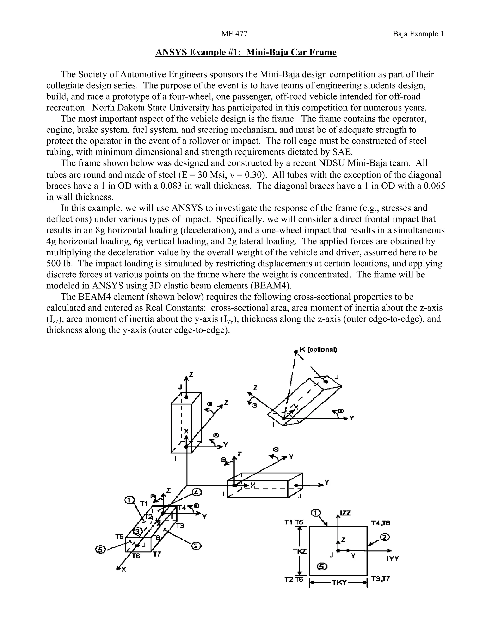
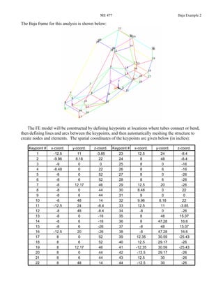
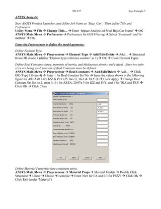
SlideShare a Scribd company logo
1 of 11
Download to read offline
ME 477 Baja Example 1
ANSYS Example #1: Mini-Baja Car Frame
The Society of Automotive Engineers sponsors the Mini-Baja design competition as part of their
collegiate design series. The purpose of the event is to have teams of engineering students design,
build, and race a prototype of a four-wheel, one passenger, off-road vehicle intended for off-road
recreation. North Dakota State University has participated in this competition for numerous years.
The most important aspect of the vehicle design is the frame. The frame contains the operator,
engine, brake system, fuel system, and steering mechanism, and must be of adequate strength to
protect the operator in the event of a rollover or impact. The roll cage must be constructed of steel
tubing, with minimum dimensional and strength requirements dictated by SAE.
The frame shown below was designed and constructed by a recent NDSU Mini-Baja team. All
tubes are round and made of steel (E = 30 Msi, ν = 0.30). All tubes with the exception of the diagonal
braces have a 1 in OD with a 0.083 in wall thickness. The diagonal braces have a 1 in OD with a 0.065
in wall thickness.
In this example, we will use ANSYS to investigate the response of the frame (e.g., stresses and
deflections) under various types of impact. Specifically, we will consider a direct frontal impact that
results in an 8g horizontal loading (deceleration), and a one-wheel impact that results in a simultaneous
4g horizontal loading, 6g vertical loading, and 2g lateral loading. The applied forces are obtained by
multiplying the deceleration value by the overall weight of the vehicle and driver, assumed here to be
500 lb. The impact loading is simulated by restricting displacements at certain locations, and applying
discrete forces at various points on the frame where the weight is concentrated. The frame will be
modeled in ANSYS using 3D elastic beam elements (BEAM4).
The BEAM4 element (shown below) requires the following cross-sectional properties to be
calculated and entered as Real Constants: cross-sectional area, area moment of inertia about the z-axis
(Izz), area moment of inertia about the y-axis (Iyy), thickness along the z-axis (outer edge-to-edge), and
thickness along the y-axis (outer edge-to-edge).
ME 477 Baja Example 2
The Baja frame for this analysis is shown below:
The FE model will be constructed by defining keypoints at locations where tubes connect or bend,
then defining lines and arcs between the keypoints, and then automatically meshing the structure to
create nodes and elements. The spatial coordinates of the keypoints are given below (in inches):
Keypoint # x-coord. y-coord. z-coord. Keypoint # x-coord. y-coord. z-coord.
1 -12.5 11 -3.85 23 12.5 24 -8.4
2 -9.96 8.18 22 24 8 48 -8.4
3 -9 0 0 25 8 0 -16
4 -8.48 0 22 26 8 6 -16
5 -8 0 52 27 8 0 -26
6 -8 6 52 28 8 6 -26
7 -8 12.17 46 29 12.5 20 -26
8 -8 0 44 30 8.48 0 22
9 -8 6 44 31 9 0 0
10 -8 48 14 32 9.96 8.18 22
11 -12.5 24 -8.4 33 12.5 11 -3.85
12 -8 48 -8.4 34 -8 0 -26
13 -8 0 -16 35 8 48 15.07
14 -8 6 -16 36 8 47.28 16.6
15 -8 6 -26 37 -8 48 15.07
16 -12.5 20 -26 38 -8 47.28 16.6
17 8 0 52 39 12.35 30.59 -25.43
18 8 6 52 40 12.5 29.17 -26
19 8 12.17 46 41 -12.35 30.59 -25.43
20 8 0 44 42 -12.5 29.17 -26
21 8 6 44 43 12.5 30 -26
22 8 48 14 44 -12.5 30 -26
ME 477 Baja Example 3
ANSYS Analysis:
Start ANSYS Product Launcher, and define Job Name as ‘Baja_Car’. Then define Title and
Preferences.
Utility Menu File Change Title… Enter ‘Impact Analysis of Mini-Baja Car Frame’ OK
ANSYS Main Menu Preferences Preferences for GUI Filtering Select ‘Structural’ and ‘h-
method’ OK
Enter the Preprocessor to define the model geometry:
Define Element Type.
ANSYS Main Menu Preprocessor Element Type Add/Edit/Delete Add… Structural
Beam 3D elastic 4 (define ‘Element type reference number’ as 1) OK Close Element Types
Define Real Constants (area, moments of inertia, and thicknesses about y and z axes). Since two tube
sizes are being used, two sets of Real Constants must be defined.
ANSYS Main Menu Preprocessor Real Constants Add/Edit/Delete Add… Click
OK (Type 1 Beam 4) Enter 1 for Real Constant Set No. Input the values shown in the following
figure for AREA (0.239), IZZ & IYY (25.34e-3), TKZ & TKY (1) Click Apply Change Real
Constant Set No. to 2, enter 0.191 for AREA, 20.97e-3 for IZZ and IYY, and 1 for TKZ and TKY
Click OK Click Close
Define Material Properties (use consistent units).
ANSYS Main Menu Preprocessor Material Props Material Models Double Click
Structural Linear Elastic Isotropic Enter 30e6 for EX and 0.3 for PRXY Click OK
Click Exit (under ‘Material’)
ME 477 Baja Example 4
Create the Keypoints by defining their spatial coordinates.
ANSYS Main Menu Preprocessor Modeling Create Keypoints In Active CS
(coordinate system) Enter Keypoint number and Location in active CS (see figure below) Click
Apply Repeat for each point listed in the table on page 2 Click OK after the last point
If a mistake is made defining a Keypoint, delete it as follows and redefine.
ANSYS Main Menu Preprocessor Modeling Delete Keypoints Select the Keypoint
with the mouse Click OK
The viewpoint and scale of the plot can be easily adjusted using the Plot Controls on the right side of
the Graphics Window. For example, click on the Isometric View button to get the Isometric view.
Also, hold down the Ctrl key on the keyboard and use the left mouse button to pan (move) the plot, the
scroll wheel to zoom in and out, or the right button to rotate the plot.
Create Lines between Keypoints. This can be done by picking the Keypoints on the plot with the
mouse, or by entering the Keypoint numbers into the command line.
ANSYS Main Menu Preprocessor Modeling Create Lines Lines Straight Line
Create all Lines by selecting (with the mouse) two Keypoints for each line (see table below). The Line
will be created automatically after the second Keypoint is selected. Otherwise, the Keypoint numbers
can be typed into the Command Line for the ‘Create Straight Line’ menu box, pressing Enter after
each Keypoint is entered. Click OK when finished
(When creating lines, it may be necessary to rotate the view or zoom in and out.)
When picking entities, if the incorrect entity is picked with the mouse, click the right mouse button
(which inverts the picking arrow), and then unpick the entity with the left mouse button. Click the right
mouse button again to rest the picking arrow.
If a mistake is made defining a Line, delete it as follows and redefine.
ANSYS Main Menu Preprocessor Modeling Delete Lines Only Select the Line with
the mouse Click OK
To see Lines and Keypoints simultaneously, replot as follows:
Utility Menu Plot Multi-Plots
Line and Keypoint numbers may turned on or off on the plot as follows:
Utility Menu PlotCtrls Numbering… Select the desired numbers for display Click OK
In the table below, each Line is listed with the corresponding Keypoints:
ME 477 Baja Example 5
Line
No. Keypoints
Line
No. Keypoints
Line
No. Keypoints
Line
No. Keypoints
1 17 18 21 2 4 41 13 14 61 24 22
2 18 21 22 4 8 42 14 15 62 10 37
3 21 20 23 4 30 43 15 34 63 22 35
4 20 17 24 8 30 44 34 13 64 10 22
5 5 8 25 9 4 45 34 27 65 38 7
6 8 9 26 21 30 46 13 25 66 36 19
7 9 6 27 2 1 47 14 26 67 23 33
8 6 5 28 1 3 48 15 28 68 16 15
9 6 18 29 3 4 49 1 14 69 12 11
10 5 17 30 32 33 50 13 3 70 24 23
11 20 8 31 33 31 51 1 33 71 40 29
12 7 6 32 31 30 52 11 23 72 42 16
13 7 9 33 3 31 53 11 16 73 30 33
14 19 18 34 33 26 54 16 29 74 4 1
15 19 21 35 26 25 55 29 23 75 30 3
16 19 7 36 25 31 56 11 1 76 11 24
17 21 32 37 26 28 57 12 24 77 11 33
18 32 30 38 28 27 58 24 39
19 30 20 39 27 25 59 12 41
20 9 2 40 28 29 60 12 10
The bends at the top and rear of the roll cage will be created using Arcs. All bends have a 3 in
centerline bend radius. In this example, the Arcs will be defined based on their end Keypoints, and
any other Keypoint that lies in the plane of the Arc, on the center-of-curvature side.
ANSYS Main Menu Preprocessor Modeling Create Lines Arcs By End KPs &
Rad Select (with the mouse) the Keypoints at the start and end of the Arc (35 and 36), or enter the
Keypoint numbers (35 and 36) in the Command Line, pressing Enter after each number is entered
Click Apply Select (with the mouse) or enter in the Command Line the Keypoint on the center-of-
curvature side and in the plane of the Arc (33). If the Command Line is used, press Enter after the
number has been entered. Click Apply You will get the following window:
Enter ‘Radius of the arc’ as 3 and check other information like P1, P2 and PC. Click Apply.
Similarly, the other Arcs can be created (all with radius of 3) using the data below:
1. P1=37, P2=38, PC=1
2. P1=41, P2=42, PC=11
3. P1=39, P2=40, PC= 23
ME 477 Baja Example 6
The Lines will be meshed automatically using the MeshTool. However, since different tubes have
different geometric properties (Real Constants), we must first assign the Real Constant sets to the
appropriate Lines:
ANSYS Main Menu Preprocessor Meshing MeshTool Under ‘Element Attributes’ scroll
in the window and click on Lines Click Set Select (with the mouse) all diagonal lines (cross-
braces) carefully (there are 8 total), or enter the Line numbers in the Command Line, pressing Enter
after each one Click OK Change ‘Real constant set number’ to 2 Click OK
The remaining lines need to be assigned to Real Constant set no. 1. Instead of selecting all the
remaining lines, we will unselect the diagonal lines. We will then be left with the remaining lines, and
we can select them all to assign them Real Constant set no. 1.
Utility Menu Select Entities… In the first window scroll and click on Lines In the second
window scroll and click on By Num/Pick Select ‘Unselect’ Click Apply Select (with the
mouse or in the Command Line) all the diagonal Lines Click OK
Utility Menu Plot Replot. You will see all the lines except the diagonal lines.
ANSYS Main Menu Preprocessor Meshing MeshTool Under ‘Element Attributes’ scroll
in the window and click on Lines Click Set Select ‘Pick All’ Change ‘Real constant set
number’ to 1 Click OK
Reselect the full set of Lines for meshing, and verify the Real Constant sets have been correctly
defined.
Utility Menu Select Everything… (this will select all the lines including the diagonal lines)
Utility Menu Plot Replot
Utility Menu PlotCtrls Numbering… Under ‘Elem/Attrib numbering’ scroll down and click
on ‘Real const num’ Click OK
Utility Menu PlotCtrls Numbering… Under ‘Elem/Attrib numbering’ scroll down and click
on ‘No numbering’ Click OK
If different materials were used in the structure, Material Property sets could be assigned to the
appropriate lines in a similar manner as the Real Constant sets were assigned.
Automatically mesh the structure (create Nodes and Elements) using the MeshTool. The size of the
Elements will be controlled using the Global Size feature, which specifies the length of the Elements.
All Elements will have approximately the same length using this method. In this example, we will use
an Element length of 0.5 in.
ANSYS Main Menu Preprocessor Meshing MeshTool Under ‘Size Controls: Global’
click Set Enter 0.5 for ‘Element edge length’ Click OK Check in Mesh Window that Lines is
displayed. If not scroll and click on Lines Click on Mesh Select ‘Pick All’
You can see how many nodes and elements are created in the Ansys Output Window. If more or less
elements are desired, repeat the last step using a different edge length.
Enter the Solution Menu to define boundary conditions and loads and run the analysis:
Define the Analysis Type.
ANSYS Main Menu Solution Analysis Type New Analysis Select Static Click OK
Apply Boundary Conditions for the frontal impact simulation. In this analysis, the nodal translations
at the four front corner Nodes (Keypoints) will be constrained.
ME 477 Baja Example 7
ANSYS Main Menu Solution Define Loads Apply Structural Displacement On
Keypoints Select (with the mouse) Keypoints 5, 6, 17 and 18 Click OK Select UX, UY and
UZ Click OK
Apply Loads to the frame. In this analysis, the 8g loading (4000 lb total) will be applied on four Nodes
(Keypoints) at which the actual loading is expected to be concentrated. The majority of the weight of
the driver and engine would be applied to the frame behind the seat. Thus, four 1000 lb loads will be
applied to the four locations shown in the following figure. More accurate results would be obtained
by better distributing the load.
ANSYS Main Menu Solution Define Loads Apply Structural Force/Moment On
Keypoints Select (with the mouse) Keypoints 3, 11, 23 and 31 Click OK Select FZ for
‘Direction of force/mom’ and enter 1000 for ‘Force/moment value’ Click OK
The loads and constraints should appear as on the following figure:
Save the Database before initiating the solution.
Ansys Toolbar SAVE_DB
Solve the model using the current Load Step (set of loads).
ANSYS Main Menu Solution Solve Curent LS Click OK
Enter the General Postprocessor to examine the results:
The deformed shape should be checked first. The actual nodal displacements can also be listed.
ME 477 Baja Example 8
ANSYS Main Menu General Postproc Plot Results Deformed Shape Select Def +
undeformed Click OK
ANSYS Main Menu General Postproc List Results Nodal Solution Select ‘DOF
Solution’ and ‘Displacement vector sum’ Click OK
Plots can be saved to a file as follows:
Utility Menu PlotCtrls Hard Copy To File… Select ‘Color,’ ‘JPEG,’ ‘Reverse Video,’
‘Portrait,’ and enter a filename (if desired) Click OK (the file will be saved in the working
directory.)
Result lists can be saved to a file by selecting ‘Save as …’ under the ‘File’ command in the output
window.
Write Element Stresses (direct and bending) into an Element Table.
ANSYS Main Menu General Postproc Element Table Define Table Add Scroll to
‘By sequence num’, highlight it and then highlight ‘LS,’ and then enter ‘LS, 1’ in the lower window as
shown in the Figure below. Label this item as ‘Sdir’ Click Apply. Repeat for the following items:
Scroll to ‘By sequence num’ and type ‘LS, 2’. Label this item as ‘Sbyi’ Click Apply
Scroll to ‘By sequence num’ and type ‘LS, 7’. Label this item as ‘Sbyj’ Click Apply
ME 477 Baja Example 9
Scroll to ‘By sequence num’ and type ‘LS, 4’. Label this item as ‘Sbzi’ Click Apply
Scroll to ‘By sequence num’ and type ‘LS, 9’. Label this item as ‘Sbzj’ Click OK
Click Close on Element Table Data
Generate a contour plot of any stress component.
ANSYS Main Menu General Postproc Element Table Plot Element Table Select a
stress (do not average at common nodes) Click OK
The maximum stress in a beam is the sum of bending and direct stresses. For a round beam, the
following formula can be used:
σmax = | σdir | + (σby
2
+ σbz
2
)1/2
This value can be computed in ANSYS, at node i or node j for each element. First, locate where the
maximum stress is (node i or node j):
ANSYS Main Menu General Postproc Element Table List Element Table Select all
stresses Click OK (Scroll to the bottom of the window to identify the maximum magnitude
(absolute value) and location of each stress)
Calculate the maximum stress at Node j (for each Element). This requires a series of calculations.
ANSYS Main Menu General Postproc Element Table Exponentiate. Enter the values as
shown in the following picture to calculate the square of SBYJ Click Apply
ME 477 Baja Example 10
Similarly, enter sbzj2, SBZJ, 2, none and 1 in the above format to calculate the square of SBZJ
Click OK
ANSYS Main Menu General Postproc Element Table Add items Enter sbjmax2, 1,
SBYJ2, 1, SBZJ2, 0 in that window. Click OK
ANSYS Main Menu General Postproc Element Table Exponentiate Enter sbjmax,
SBJMAX2, 0.5, none, and 1 Click OK
ANSYS Main Menu General Postproc Element Table Abs Value Option Click on yes
to use absolute values Click OK
ANSYS Main Menu General Postproc Element Table Add items Enter smaxj, 1, SDIR,
1, SBJMAX and 0 Click OK
A contour plot of the maximum stress can now be generated.
ANSYS Main Menu General Postproc Element Table Plot Element Table SMAXJ
Click OK
The plot is shown in the following figure. The process could be repeated at Node i.
For a rectangular beam, the maximum stress is
σmax = | σdir | + | σby |+ | σbz |
ME 477 Baja Example 11
ANSYS also has a function to compute the maximum and minimum stresses as the simple sum of direct
and bending. This is not strictly accurate for round beams, but is usually close enough. These stresses
can be added to the element table as follows:
ANSYS Main Menu General Postproc Element Table Define Table Add Scroll to
‘By sequence num’, highlight it and then highlight ‘NMISC,’ and then enter ‘NMISC, 1’ in the lower
window. Label this item as ‘Smaxi’ Click Apply. Repeat for the following items:
Scroll to ‘By sequence num’ and type ‘NMISC, 3’. Label this item as ‘Smaxj’ Click Apply
Scroll to ‘By sequence num’ and type ‘NMISC, 2’. Label this item as ‘Smini’ Click Apply
Scroll to ‘By sequence num’ and type ‘NMISC, 4’. Label this item as ‘Sminj’ Click Apply
The one-wheel impact condition could be simulated by restricting the nodal displacements at the
Keypoints where the A-arms and shock of the front wheel connect to the frame, as shown in the figure
below:
The loads (4g horizontal, 6g vertical, 2g lateral) could be distributed to the four Keypoints shown in
the following figure.
The analysis could then be re-run in the same manner as the previous analysis.

More Related Content

What's hot

What's hot (20)

AutoCad Basic tutorial
AutoCad Basic tutorialAutoCad Basic tutorial
AutoCad Basic tutorial
 
Intro to AutoCAD
Intro to AutoCADIntro to AutoCAD
Intro to AutoCAD
 
Autocad commands-1
Autocad commands-1Autocad commands-1
Autocad commands-1
 
Auto cad tutorial
Auto cad tutorialAuto cad tutorial
Auto cad tutorial
 
Autocad chapter 4 for mobile use.
Autocad chapter 4 for mobile use.Autocad chapter 4 for mobile use.
Autocad chapter 4 for mobile use.
 
Introduction to autocad_lt
Introduction to autocad_ltIntroduction to autocad_lt
Introduction to autocad_lt
 
Commands in AutoCAD
Commands in AutoCADCommands in AutoCAD
Commands in AutoCAD
 
Autocad Commands
Autocad CommandsAutocad Commands
Autocad Commands
 
Autocad2011 2
Autocad2011 2Autocad2011 2
Autocad2011 2
 
TAO Fayan_Canvas design by tcltk_Final report
TAO Fayan_Canvas design by tcltk_Final reportTAO Fayan_Canvas design by tcltk_Final report
TAO Fayan_Canvas design by tcltk_Final report
 
Presentation On Auto Cad
Presentation On Auto CadPresentation On Auto Cad
Presentation On Auto Cad
 
Finite Element Simulation with Ansys Workbench 14
Finite Element Simulation with Ansys Workbench 14Finite Element Simulation with Ansys Workbench 14
Finite Element Simulation with Ansys Workbench 14
 
Auto cad
Auto cadAuto cad
Auto cad
 
Practical work 2
Practical work 2Practical work 2
Practical work 2
 
Practical work 3
Practical work 3Practical work 3
Practical work 3
 
บทนำ
บทนำบทนำ
บทนำ
 
s1233587_Report
s1233587_Reports1233587_Report
s1233587_Report
 
CAE_s1233587
CAE_s1233587CAE_s1233587
CAE_s1233587
 
Auto cad ppt
Auto cad pptAuto cad ppt
Auto cad ppt
 
Auto cad
Auto cadAuto cad
Auto cad
 

Viewers also liked

small business
small businesssmall business
small businesshome
 
Design and construction of formula sae
Design and construction of formula saeDesign and construction of formula sae
Design and construction of formula saeCADmantra Technologies
 
The Team H2politO: vehicles for low consumption competitions using HyperWorks
The Team H2politO: vehicles for low consumption competitions using HyperWorks  The Team H2politO: vehicles for low consumption competitions using HyperWorks
The Team H2politO: vehicles for low consumption competitions using HyperWorks Altair
 
Design a solar car
Design a solar carDesign a solar car
Design a solar carhome
 
Formula 1000 Frame Design
Formula 1000 Frame DesignFormula 1000 Frame Design
Formula 1000 Frame Designdmcmah0n
 
Design and construction of formula sae
Design and construction of formula saeDesign and construction of formula sae
Design and construction of formula saeCADmantra Technologies
 
Seismic behavior of rc elevated water tankunder different types of staging pa...
Seismic behavior of rc elevated water tankunder different types of staging pa...Seismic behavior of rc elevated water tankunder different types of staging pa...
Seismic behavior of rc elevated water tankunder different types of staging pa...CADmantra Technologies
 
Chassis
ChassisChassis
Chassishome
 
Formula SAE vehicle
Formula SAE vehicleFormula SAE vehicle
Formula SAE vehicleAltair
 
Alex Hsia Monocoque Overview
Alex Hsia Monocoque OverviewAlex Hsia Monocoque Overview
Alex Hsia Monocoque OverviewAlex Hsia
 
Final Chassis Report 2010
Final Chassis Report 2010Final Chassis Report 2010
Final Chassis Report 2010Thomas Ayres
 
Dalhousie FSAE 2013 frame presentation
Dalhousie FSAE 2013 frame presentationDalhousie FSAE 2013 frame presentation
Dalhousie FSAE 2013 frame presentationCorey Ireland
 
Stress Analysis of a heavy duty vehicle chassis by using FEA
Stress Analysis of a heavy duty vehicle chassis by using FEAStress Analysis of a heavy duty vehicle chassis by using FEA
Stress Analysis of a heavy duty vehicle chassis by using FEADigitech Rathod
 
Sensing in automotive powertrain and braking systems
Sensing in automotive powertrain and braking systemsSensing in automotive powertrain and braking systems
Sensing in automotive powertrain and braking systemsamged radhi
 
Dynamic weight transfer in vehicle
Dynamic weight transfer in vehicleDynamic weight transfer in vehicle
Dynamic weight transfer in vehicleRohan Sahdev
 
Go karting project report Degree level
Go karting project report Degree levelGo karting project report Degree level
Go karting project report Degree levelAniket pawar
 
Constructing a go kart
Constructing a go kartConstructing a go kart
Constructing a go kartsbonnoiv
 

Viewers also liked (20)

small business
small businesssmall business
small business
 
Design and construction of formula sae
Design and construction of formula saeDesign and construction of formula sae
Design and construction of formula sae
 
Shell Project Report.
Shell Project Report.Shell Project Report.
Shell Project Report.
 
The Team H2politO: vehicles for low consumption competitions using HyperWorks
The Team H2politO: vehicles for low consumption competitions using HyperWorks  The Team H2politO: vehicles for low consumption competitions using HyperWorks
The Team H2politO: vehicles for low consumption competitions using HyperWorks
 
Design a solar car
Design a solar carDesign a solar car
Design a solar car
 
Formula 1000 Frame Design
Formula 1000 Frame DesignFormula 1000 Frame Design
Formula 1000 Frame Design
 
Design and construction of formula sae
Design and construction of formula saeDesign and construction of formula sae
Design and construction of formula sae
 
Seismic behavior of rc elevated water tankunder different types of staging pa...
Seismic behavior of rc elevated water tankunder different types of staging pa...Seismic behavior of rc elevated water tankunder different types of staging pa...
Seismic behavior of rc elevated water tankunder different types of staging pa...
 
Seismic design of_elevated_tanks
Seismic design of_elevated_tanksSeismic design of_elevated_tanks
Seismic design of_elevated_tanks
 
Chassis
ChassisChassis
Chassis
 
Formula SAE vehicle
Formula SAE vehicleFormula SAE vehicle
Formula SAE vehicle
 
Alex Hsia Monocoque Overview
Alex Hsia Monocoque OverviewAlex Hsia Monocoque Overview
Alex Hsia Monocoque Overview
 
Final Chassis Report 2010
Final Chassis Report 2010Final Chassis Report 2010
Final Chassis Report 2010
 
Dalhousie FSAE 2013 frame presentation
Dalhousie FSAE 2013 frame presentationDalhousie FSAE 2013 frame presentation
Dalhousie FSAE 2013 frame presentation
 
Stress Analysis of a heavy duty vehicle chassis by using FEA
Stress Analysis of a heavy duty vehicle chassis by using FEAStress Analysis of a heavy duty vehicle chassis by using FEA
Stress Analysis of a heavy duty vehicle chassis by using FEA
 
Sensing in automotive powertrain and braking systems
Sensing in automotive powertrain and braking systemsSensing in automotive powertrain and braking systems
Sensing in automotive powertrain and braking systems
 
water tank analysis
water tank analysiswater tank analysis
water tank analysis
 
Dynamic weight transfer in vehicle
Dynamic weight transfer in vehicleDynamic weight transfer in vehicle
Dynamic weight transfer in vehicle
 
Go karting project report Degree level
Go karting project report Degree levelGo karting project report Degree level
Go karting project report Degree level
 
Constructing a go kart
Constructing a go kartConstructing a go kart
Constructing a go kart
 

Similar to Baja example

1 P a g e 2105 ENG, Mechanics of.docx
1  P a g e   2105 ENG, Mechanics of.docx1  P a g e   2105 ENG, Mechanics of.docx
1 P a g e 2105 ENG, Mechanics of.docxhoney725342
 
Workshop12 skewplate
Workshop12 skewplateWorkshop12 skewplate
Workshop12 skewplatemmd110
 
Two dimensional truss
Two dimensional trussTwo dimensional truss
Two dimensional trussESWARANM92
 
Ansys beam problem
Ansys beam problemAnsys beam problem
Ansys beam problemnmahi96
 
AutoCAD-ppt.pptx
AutoCAD-ppt.pptxAutoCAD-ppt.pptx
AutoCAD-ppt.pptxABUFAZZIL
 
Automated Laser Reflection Report
Automated Laser Reflection ReportAutomated Laser Reflection Report
Automated Laser Reflection ReportNan Li
 
AutoCAD ppt presentation new.pptx
AutoCAD ppt presentation new.pptxAutoCAD ppt presentation new.pptx
AutoCAD ppt presentation new.pptxVasu Sahu
 
presentationprintTemp.ppt auto cad presentation
presentationprintTemp.ppt auto cad presentationpresentationprintTemp.ppt auto cad presentation
presentationprintTemp.ppt auto cad presentationvikramchandrachoudha
 
Civil 3d Workflow_NOLOGO
Civil 3d Workflow_NOLOGOCivil 3d Workflow_NOLOGO
Civil 3d Workflow_NOLOGOGary Cassidy
 
Autocad second level tutorial
Autocad second level tutorialAutocad second level tutorial
Autocad second level tutorialJo Padilha
 
AutoCAD-ppt.pptx
AutoCAD-ppt.pptxAutoCAD-ppt.pptx
AutoCAD-ppt.pptxMadhu797724
 
Structural analysis of a brake disc.pptm
Structural analysis of a brake disc.pptmStructural analysis of a brake disc.pptm
Structural analysis of a brake disc.pptmVedprakash Arya
 
Acad civil3 d_points_manual
Acad civil3 d_points_manualAcad civil3 d_points_manual
Acad civil3 d_points_manualMiodrag Hrenek
 

Similar to Baja example (20)

1 P a g e 2105 ENG, Mechanics of.docx
1  P a g e   2105 ENG, Mechanics of.docx1  P a g e   2105 ENG, Mechanics of.docx
1 P a g e 2105 ENG, Mechanics of.docx
 
Workshop12 skewplate
Workshop12 skewplateWorkshop12 skewplate
Workshop12 skewplate
 
Two dimensional truss
Two dimensional trussTwo dimensional truss
Two dimensional truss
 
Ansys beam problem
Ansys beam problemAnsys beam problem
Ansys beam problem
 
AutoCAD-ppt.pptx
AutoCAD-ppt.pptxAutoCAD-ppt.pptx
AutoCAD-ppt.pptx
 
Tutorial ads
Tutorial adsTutorial ads
Tutorial ads
 
Automated Laser Reflection Report
Automated Laser Reflection ReportAutomated Laser Reflection Report
Automated Laser Reflection Report
 
AutoCAD-ppt.pptx
AutoCAD-ppt.pptxAutoCAD-ppt.pptx
AutoCAD-ppt.pptx
 
AutoCAD ppt presentation new.pptx
AutoCAD ppt presentation new.pptxAutoCAD ppt presentation new.pptx
AutoCAD ppt presentation new.pptx
 
presentationprintTemp.ppt auto cad presentation
presentationprintTemp.ppt auto cad presentationpresentationprintTemp.ppt auto cad presentation
presentationprintTemp.ppt auto cad presentation
 
Patchantenna
PatchantennaPatchantenna
Patchantenna
 
autocad demo.pptx
autocad demo.pptxautocad demo.pptx
autocad demo.pptx
 
FEMAP TUTORIAL AE410
FEMAP TUTORIAL AE410FEMAP TUTORIAL AE410
FEMAP TUTORIAL AE410
 
PRO ENGINEER BASIC
PRO ENGINEER BASICPRO ENGINEER BASIC
PRO ENGINEER BASIC
 
Civil 3d workflow
Civil 3d workflowCivil 3d workflow
Civil 3d workflow
 
Civil 3d Workflow_NOLOGO
Civil 3d Workflow_NOLOGOCivil 3d Workflow_NOLOGO
Civil 3d Workflow_NOLOGO
 
Autocad second level tutorial
Autocad second level tutorialAutocad second level tutorial
Autocad second level tutorial
 
AutoCAD-ppt.pptx
AutoCAD-ppt.pptxAutoCAD-ppt.pptx
AutoCAD-ppt.pptx
 
Structural analysis of a brake disc.pptm
Structural analysis of a brake disc.pptmStructural analysis of a brake disc.pptm
Structural analysis of a brake disc.pptm
 
Acad civil3 d_points_manual
Acad civil3 d_points_manualAcad civil3 d_points_manual
Acad civil3 d_points_manual
 

More from CADmantra Technologies

Analysis of 3+ story building in staad pro
Analysis of 3+ story building in staad proAnalysis of 3+ story building in staad pro
Analysis of 3+ story building in staad proCADmantra Technologies
 
Analysisanddesignofamulti storey staad pro.
Analysisanddesignofamulti storey staad pro.Analysisanddesignofamulti storey staad pro.
Analysisanddesignofamulti storey staad pro.CADmantra Technologies
 

More from CADmantra Technologies (20)

RCC BMD
RCC BMDRCC BMD
RCC BMD
 
Machine drawing
Machine drawingMachine drawing
Machine drawing
 
Analysis of connecting rod in ansys
Analysis of connecting rod in ansysAnalysis of connecting rod in ansys
Analysis of connecting rod in ansys
 
Analysis of industrial shed
Analysis of industrial shedAnalysis of industrial shed
Analysis of industrial shed
 
Analysis of 3+ story building in staad pro
Analysis of 3+ story building in staad proAnalysis of 3+ story building in staad pro
Analysis of 3+ story building in staad pro
 
Concrete shrinkage prediction
Concrete shrinkage predictionConcrete shrinkage prediction
Concrete shrinkage prediction
 
Civil drawing detail
Civil drawing detailCivil drawing detail
Civil drawing detail
 
Analysis of warehouse in staad pro.
Analysis of warehouse in staad pro. Analysis of warehouse in staad pro.
Analysis of warehouse in staad pro.
 
Analysisanddesignofamulti storey staad pro.
Analysisanddesignofamulti storey staad pro.Analysisanddesignofamulti storey staad pro.
Analysisanddesignofamulti storey staad pro.
 
Analysis of chassis
Analysis of chassisAnalysis of chassis
Analysis of chassis
 
Aerodynamics study on spoiler of car
Aerodynamics study on spoiler of carAerodynamics study on spoiler of car
Aerodynamics study on spoiler of car
 
Hvac introduction
Hvac introductionHvac introduction
Hvac introduction
 
Autocad presentation
Autocad presentationAutocad presentation
Autocad presentation
 
Optimization of chassis ansys
Optimization of chassis ansysOptimization of chassis ansys
Optimization of chassis ansys
 
Cad standards for biggner
Cad standards for biggner Cad standards for biggner
Cad standards for biggner
 
Analysis report volume3
Analysis report volume3Analysis report volume3
Analysis report volume3
 
Analysis report volume 1
Analysis report volume 1Analysis report volume 1
Analysis report volume 1
 
Analysis report volume 10
Analysis report volume 10Analysis report volume 10
Analysis report volume 10
 
Analysis report volume 9
Analysis report volume 9Analysis report volume 9
Analysis report volume 9
 
Analysis report volume 2
Analysis report volume 2Analysis report volume 2
Analysis report volume 2
 

Recently uploaded

Business Development and Product Strategy for a SME named SARL based in Leban...
Business Development and Product Strategy for a SME named SARL based in Leban...Business Development and Product Strategy for a SME named SARL based in Leban...
Business Development and Product Strategy for a SME named SARL based in Leban...Soham Mondal
 
办理学位证(纽伦堡大学文凭证书)纽伦堡大学毕业证成绩单原版一模一样
办理学位证(纽伦堡大学文凭证书)纽伦堡大学毕业证成绩单原版一模一样办理学位证(纽伦堡大学文凭证书)纽伦堡大学毕业证成绩单原版一模一样
办理学位证(纽伦堡大学文凭证书)纽伦堡大学毕业证成绩单原版一模一样umasea
 
定制(UOIT学位证)加拿大安大略理工大学毕业证成绩单原版一比一
 定制(UOIT学位证)加拿大安大略理工大学毕业证成绩单原版一比一 定制(UOIT学位证)加拿大安大略理工大学毕业证成绩单原版一比一
定制(UOIT学位证)加拿大安大略理工大学毕业证成绩单原版一比一Fs sss
 
Notes of bca Question paper for exams and tests
Notes of bca Question paper for exams and testsNotes of bca Question paper for exams and tests
Notes of bca Question paper for exams and testspriyanshukumar97908
 
do's and don'ts in Telephone Interview of Job
do's and don'ts in Telephone Interview of Jobdo's and don'ts in Telephone Interview of Job
do's and don'ts in Telephone Interview of JobRemote DBA Services
 
女王大学硕士毕业证成绩单(加急办理)认证海外毕业证
女王大学硕士毕业证成绩单(加急办理)认证海外毕业证女王大学硕士毕业证成绩单(加急办理)认证海外毕业证
女王大学硕士毕业证成绩单(加急办理)认证海外毕业证obuhobo
 
Black and White Minimalist Co Letter.pdf
Black and White Minimalist Co Letter.pdfBlack and White Minimalist Co Letter.pdf
Black and White Minimalist Co Letter.pdfpadillaangelina0023
 
Preventing and ending sexual harassment in the workplace.pptx
Preventing and ending sexual harassment in the workplace.pptxPreventing and ending sexual harassment in the workplace.pptx
Preventing and ending sexual harassment in the workplace.pptxGry Tina Tinde
 
VIP Russian Call Girls in Bhilai Deepika 8250192130 Independent Escort Servic...
VIP Russian Call Girls in Bhilai Deepika 8250192130 Independent Escort Servic...VIP Russian Call Girls in Bhilai Deepika 8250192130 Independent Escort Servic...
VIP Russian Call Girls in Bhilai Deepika 8250192130 Independent Escort Servic...Suhani Kapoor
 
VIP Call Girls in Cuttack Aarohi 8250192130 Independent Escort Service Cuttack
VIP Call Girls in Cuttack Aarohi 8250192130 Independent Escort Service CuttackVIP Call Girls in Cuttack Aarohi 8250192130 Independent Escort Service Cuttack
VIP Call Girls in Cuttack Aarohi 8250192130 Independent Escort Service CuttackSuhani Kapoor
 
(Call Girls) in Lucknow Real photos of Female Escorts 👩🏼‍❤️‍💋‍👩🏻 8923113531 ➝...
(Call Girls) in Lucknow Real photos of Female Escorts 👩🏼‍❤️‍💋‍👩🏻 8923113531 ➝...(Call Girls) in Lucknow Real photos of Female Escorts 👩🏼‍❤️‍💋‍👩🏻 8923113531 ➝...
(Call Girls) in Lucknow Real photos of Female Escorts 👩🏼‍❤️‍💋‍👩🏻 8923113531 ➝...gurkirankumar98700
 
原版快速办理MQU毕业证麦考瑞大学毕业证成绩单留信学历认证
原版快速办理MQU毕业证麦考瑞大学毕业证成绩单留信学历认证原版快速办理MQU毕业证麦考瑞大学毕业证成绩单留信学历认证
原版快速办理MQU毕业证麦考瑞大学毕业证成绩单留信学历认证nhjeo1gg
 
办理学位证(UoM证书)北安普顿大学毕业证成绩单原版一比一
办理学位证(UoM证书)北安普顿大学毕业证成绩单原版一比一办理学位证(UoM证书)北安普顿大学毕业证成绩单原版一比一
办理学位证(UoM证书)北安普顿大学毕业证成绩单原版一比一A SSS
 
Low Rate Call Girls Gorakhpur Anika 8250192130 Independent Escort Service Gor...
Low Rate Call Girls Gorakhpur Anika 8250192130 Independent Escort Service Gor...Low Rate Call Girls Gorakhpur Anika 8250192130 Independent Escort Service Gor...
Low Rate Call Girls Gorakhpur Anika 8250192130 Independent Escort Service Gor...Suhani Kapoor
 
VIP High Profile Call Girls Jamshedpur Aarushi 8250192130 Independent Escort ...
VIP High Profile Call Girls Jamshedpur Aarushi 8250192130 Independent Escort ...VIP High Profile Call Girls Jamshedpur Aarushi 8250192130 Independent Escort ...
VIP High Profile Call Girls Jamshedpur Aarushi 8250192130 Independent Escort ...Suhani Kapoor
 
办理学位证(Massey证书)新西兰梅西大学毕业证成绩单原版一比一
办理学位证(Massey证书)新西兰梅西大学毕业证成绩单原版一比一办理学位证(Massey证书)新西兰梅西大学毕业证成绩单原版一比一
办理学位证(Massey证书)新西兰梅西大学毕业证成绩单原版一比一A SSS
 
VIP Call Girl Bhilai Aashi 8250192130 Independent Escort Service Bhilai
VIP Call Girl Bhilai Aashi 8250192130 Independent Escort Service BhilaiVIP Call Girl Bhilai Aashi 8250192130 Independent Escort Service Bhilai
VIP Call Girl Bhilai Aashi 8250192130 Independent Escort Service BhilaiSuhani Kapoor
 
Call Girls In Bhikaji Cama Place 24/7✡️9711147426✡️ Escorts Service
Call Girls In Bhikaji Cama Place 24/7✡️9711147426✡️ Escorts ServiceCall Girls In Bhikaji Cama Place 24/7✡️9711147426✡️ Escorts Service
Call Girls In Bhikaji Cama Place 24/7✡️9711147426✡️ Escorts Servicejennyeacort
 
加利福尼亚大学伯克利分校硕士毕业证成绩单(价格咨询)学位证书pdf
加利福尼亚大学伯克利分校硕士毕业证成绩单(价格咨询)学位证书pdf加利福尼亚大学伯克利分校硕士毕业证成绩单(价格咨询)学位证书pdf
加利福尼亚大学伯克利分校硕士毕业证成绩单(价格咨询)学位证书pdfobuhobo
 

Recently uploaded (20)

Call Girls In Prashant Vihar꧁❤ 🔝 9953056974🔝❤꧂ Escort ServiCe
Call Girls In Prashant Vihar꧁❤ 🔝 9953056974🔝❤꧂ Escort ServiCeCall Girls In Prashant Vihar꧁❤ 🔝 9953056974🔝❤꧂ Escort ServiCe
Call Girls In Prashant Vihar꧁❤ 🔝 9953056974🔝❤꧂ Escort ServiCe
 
Business Development and Product Strategy for a SME named SARL based in Leban...
Business Development and Product Strategy for a SME named SARL based in Leban...Business Development and Product Strategy for a SME named SARL based in Leban...
Business Development and Product Strategy for a SME named SARL based in Leban...
 
办理学位证(纽伦堡大学文凭证书)纽伦堡大学毕业证成绩单原版一模一样
办理学位证(纽伦堡大学文凭证书)纽伦堡大学毕业证成绩单原版一模一样办理学位证(纽伦堡大学文凭证书)纽伦堡大学毕业证成绩单原版一模一样
办理学位证(纽伦堡大学文凭证书)纽伦堡大学毕业证成绩单原版一模一样
 
定制(UOIT学位证)加拿大安大略理工大学毕业证成绩单原版一比一
 定制(UOIT学位证)加拿大安大略理工大学毕业证成绩单原版一比一 定制(UOIT学位证)加拿大安大略理工大学毕业证成绩单原版一比一
定制(UOIT学位证)加拿大安大略理工大学毕业证成绩单原版一比一
 
Notes of bca Question paper for exams and tests
Notes of bca Question paper for exams and testsNotes of bca Question paper for exams and tests
Notes of bca Question paper for exams and tests
 
do's and don'ts in Telephone Interview of Job
do's and don'ts in Telephone Interview of Jobdo's and don'ts in Telephone Interview of Job
do's and don'ts in Telephone Interview of Job
 
女王大学硕士毕业证成绩单(加急办理)认证海外毕业证
女王大学硕士毕业证成绩单(加急办理)认证海外毕业证女王大学硕士毕业证成绩单(加急办理)认证海外毕业证
女王大学硕士毕业证成绩单(加急办理)认证海外毕业证
 
Black and White Minimalist Co Letter.pdf
Black and White Minimalist Co Letter.pdfBlack and White Minimalist Co Letter.pdf
Black and White Minimalist Co Letter.pdf
 
Preventing and ending sexual harassment in the workplace.pptx
Preventing and ending sexual harassment in the workplace.pptxPreventing and ending sexual harassment in the workplace.pptx
Preventing and ending sexual harassment in the workplace.pptx
 
VIP Russian Call Girls in Bhilai Deepika 8250192130 Independent Escort Servic...
VIP Russian Call Girls in Bhilai Deepika 8250192130 Independent Escort Servic...VIP Russian Call Girls in Bhilai Deepika 8250192130 Independent Escort Servic...
VIP Russian Call Girls in Bhilai Deepika 8250192130 Independent Escort Servic...
 
VIP Call Girls in Cuttack Aarohi 8250192130 Independent Escort Service Cuttack
VIP Call Girls in Cuttack Aarohi 8250192130 Independent Escort Service CuttackVIP Call Girls in Cuttack Aarohi 8250192130 Independent Escort Service Cuttack
VIP Call Girls in Cuttack Aarohi 8250192130 Independent Escort Service Cuttack
 
(Call Girls) in Lucknow Real photos of Female Escorts 👩🏼‍❤️‍💋‍👩🏻 8923113531 ➝...
(Call Girls) in Lucknow Real photos of Female Escorts 👩🏼‍❤️‍💋‍👩🏻 8923113531 ➝...(Call Girls) in Lucknow Real photos of Female Escorts 👩🏼‍❤️‍💋‍👩🏻 8923113531 ➝...
(Call Girls) in Lucknow Real photos of Female Escorts 👩🏼‍❤️‍💋‍👩🏻 8923113531 ➝...
 
原版快速办理MQU毕业证麦考瑞大学毕业证成绩单留信学历认证
原版快速办理MQU毕业证麦考瑞大学毕业证成绩单留信学历认证原版快速办理MQU毕业证麦考瑞大学毕业证成绩单留信学历认证
原版快速办理MQU毕业证麦考瑞大学毕业证成绩单留信学历认证
 
办理学位证(UoM证书)北安普顿大学毕业证成绩单原版一比一
办理学位证(UoM证书)北安普顿大学毕业证成绩单原版一比一办理学位证(UoM证书)北安普顿大学毕业证成绩单原版一比一
办理学位证(UoM证书)北安普顿大学毕业证成绩单原版一比一
 
Low Rate Call Girls Gorakhpur Anika 8250192130 Independent Escort Service Gor...
Low Rate Call Girls Gorakhpur Anika 8250192130 Independent Escort Service Gor...Low Rate Call Girls Gorakhpur Anika 8250192130 Independent Escort Service Gor...
Low Rate Call Girls Gorakhpur Anika 8250192130 Independent Escort Service Gor...
 
VIP High Profile Call Girls Jamshedpur Aarushi 8250192130 Independent Escort ...
VIP High Profile Call Girls Jamshedpur Aarushi 8250192130 Independent Escort ...VIP High Profile Call Girls Jamshedpur Aarushi 8250192130 Independent Escort ...
VIP High Profile Call Girls Jamshedpur Aarushi 8250192130 Independent Escort ...
 
办理学位证(Massey证书)新西兰梅西大学毕业证成绩单原版一比一
办理学位证(Massey证书)新西兰梅西大学毕业证成绩单原版一比一办理学位证(Massey证书)新西兰梅西大学毕业证成绩单原版一比一
办理学位证(Massey证书)新西兰梅西大学毕业证成绩单原版一比一
 
VIP Call Girl Bhilai Aashi 8250192130 Independent Escort Service Bhilai
VIP Call Girl Bhilai Aashi 8250192130 Independent Escort Service BhilaiVIP Call Girl Bhilai Aashi 8250192130 Independent Escort Service Bhilai
VIP Call Girl Bhilai Aashi 8250192130 Independent Escort Service Bhilai
 
Call Girls In Bhikaji Cama Place 24/7✡️9711147426✡️ Escorts Service
Call Girls In Bhikaji Cama Place 24/7✡️9711147426✡️ Escorts ServiceCall Girls In Bhikaji Cama Place 24/7✡️9711147426✡️ Escorts Service
Call Girls In Bhikaji Cama Place 24/7✡️9711147426✡️ Escorts Service
 
加利福尼亚大学伯克利分校硕士毕业证成绩单(价格咨询)学位证书pdf
加利福尼亚大学伯克利分校硕士毕业证成绩单(价格咨询)学位证书pdf加利福尼亚大学伯克利分校硕士毕业证成绩单(价格咨询)学位证书pdf
加利福尼亚大学伯克利分校硕士毕业证成绩单(价格咨询)学位证书pdf
 

Baja example

  • 1. ME 477 Baja Example 1 ANSYS Example #1: Mini-Baja Car Frame The Society of Automotive Engineers sponsors the Mini-Baja design competition as part of their collegiate design series. The purpose of the event is to have teams of engineering students design, build, and race a prototype of a four-wheel, one passenger, off-road vehicle intended for off-road recreation. North Dakota State University has participated in this competition for numerous years. The most important aspect of the vehicle design is the frame. The frame contains the operator, engine, brake system, fuel system, and steering mechanism, and must be of adequate strength to protect the operator in the event of a rollover or impact. The roll cage must be constructed of steel tubing, with minimum dimensional and strength requirements dictated by SAE. The frame shown below was designed and constructed by a recent NDSU Mini-Baja team. All tubes are round and made of steel (E = 30 Msi, ν = 0.30). All tubes with the exception of the diagonal braces have a 1 in OD with a 0.083 in wall thickness. The diagonal braces have a 1 in OD with a 0.065 in wall thickness. In this example, we will use ANSYS to investigate the response of the frame (e.g., stresses and deflections) under various types of impact. Specifically, we will consider a direct frontal impact that results in an 8g horizontal loading (deceleration), and a one-wheel impact that results in a simultaneous 4g horizontal loading, 6g vertical loading, and 2g lateral loading. The applied forces are obtained by multiplying the deceleration value by the overall weight of the vehicle and driver, assumed here to be 500 lb. The impact loading is simulated by restricting displacements at certain locations, and applying discrete forces at various points on the frame where the weight is concentrated. The frame will be modeled in ANSYS using 3D elastic beam elements (BEAM4). The BEAM4 element (shown below) requires the following cross-sectional properties to be calculated and entered as Real Constants: cross-sectional area, area moment of inertia about the z-axis (Izz), area moment of inertia about the y-axis (Iyy), thickness along the z-axis (outer edge-to-edge), and thickness along the y-axis (outer edge-to-edge).
  • 2. ME 477 Baja Example 2 The Baja frame for this analysis is shown below: The FE model will be constructed by defining keypoints at locations where tubes connect or bend, then defining lines and arcs between the keypoints, and then automatically meshing the structure to create nodes and elements. The spatial coordinates of the keypoints are given below (in inches): Keypoint # x-coord. y-coord. z-coord. Keypoint # x-coord. y-coord. z-coord. 1 -12.5 11 -3.85 23 12.5 24 -8.4 2 -9.96 8.18 22 24 8 48 -8.4 3 -9 0 0 25 8 0 -16 4 -8.48 0 22 26 8 6 -16 5 -8 0 52 27 8 0 -26 6 -8 6 52 28 8 6 -26 7 -8 12.17 46 29 12.5 20 -26 8 -8 0 44 30 8.48 0 22 9 -8 6 44 31 9 0 0 10 -8 48 14 32 9.96 8.18 22 11 -12.5 24 -8.4 33 12.5 11 -3.85 12 -8 48 -8.4 34 -8 0 -26 13 -8 0 -16 35 8 48 15.07 14 -8 6 -16 36 8 47.28 16.6 15 -8 6 -26 37 -8 48 15.07 16 -12.5 20 -26 38 -8 47.28 16.6 17 8 0 52 39 12.35 30.59 -25.43 18 8 6 52 40 12.5 29.17 -26 19 8 12.17 46 41 -12.35 30.59 -25.43 20 8 0 44 42 -12.5 29.17 -26 21 8 6 44 43 12.5 30 -26 22 8 48 14 44 -12.5 30 -26
  • 3. ME 477 Baja Example 3 ANSYS Analysis: Start ANSYS Product Launcher, and define Job Name as ‘Baja_Car’. Then define Title and Preferences. Utility Menu File Change Title… Enter ‘Impact Analysis of Mini-Baja Car Frame’ OK ANSYS Main Menu Preferences Preferences for GUI Filtering Select ‘Structural’ and ‘h- method’ OK Enter the Preprocessor to define the model geometry: Define Element Type. ANSYS Main Menu Preprocessor Element Type Add/Edit/Delete Add… Structural Beam 3D elastic 4 (define ‘Element type reference number’ as 1) OK Close Element Types Define Real Constants (area, moments of inertia, and thicknesses about y and z axes). Since two tube sizes are being used, two sets of Real Constants must be defined. ANSYS Main Menu Preprocessor Real Constants Add/Edit/Delete Add… Click OK (Type 1 Beam 4) Enter 1 for Real Constant Set No. Input the values shown in the following figure for AREA (0.239), IZZ & IYY (25.34e-3), TKZ & TKY (1) Click Apply Change Real Constant Set No. to 2, enter 0.191 for AREA, 20.97e-3 for IZZ and IYY, and 1 for TKZ and TKY Click OK Click Close Define Material Properties (use consistent units). ANSYS Main Menu Preprocessor Material Props Material Models Double Click Structural Linear Elastic Isotropic Enter 30e6 for EX and 0.3 for PRXY Click OK Click Exit (under ‘Material’)
  • 4. ME 477 Baja Example 4 Create the Keypoints by defining their spatial coordinates. ANSYS Main Menu Preprocessor Modeling Create Keypoints In Active CS (coordinate system) Enter Keypoint number and Location in active CS (see figure below) Click Apply Repeat for each point listed in the table on page 2 Click OK after the last point If a mistake is made defining a Keypoint, delete it as follows and redefine. ANSYS Main Menu Preprocessor Modeling Delete Keypoints Select the Keypoint with the mouse Click OK The viewpoint and scale of the plot can be easily adjusted using the Plot Controls on the right side of the Graphics Window. For example, click on the Isometric View button to get the Isometric view. Also, hold down the Ctrl key on the keyboard and use the left mouse button to pan (move) the plot, the scroll wheel to zoom in and out, or the right button to rotate the plot. Create Lines between Keypoints. This can be done by picking the Keypoints on the plot with the mouse, or by entering the Keypoint numbers into the command line. ANSYS Main Menu Preprocessor Modeling Create Lines Lines Straight Line Create all Lines by selecting (with the mouse) two Keypoints for each line (see table below). The Line will be created automatically after the second Keypoint is selected. Otherwise, the Keypoint numbers can be typed into the Command Line for the ‘Create Straight Line’ menu box, pressing Enter after each Keypoint is entered. Click OK when finished (When creating lines, it may be necessary to rotate the view or zoom in and out.) When picking entities, if the incorrect entity is picked with the mouse, click the right mouse button (which inverts the picking arrow), and then unpick the entity with the left mouse button. Click the right mouse button again to rest the picking arrow. If a mistake is made defining a Line, delete it as follows and redefine. ANSYS Main Menu Preprocessor Modeling Delete Lines Only Select the Line with the mouse Click OK To see Lines and Keypoints simultaneously, replot as follows: Utility Menu Plot Multi-Plots Line and Keypoint numbers may turned on or off on the plot as follows: Utility Menu PlotCtrls Numbering… Select the desired numbers for display Click OK In the table below, each Line is listed with the corresponding Keypoints:
  • 5. ME 477 Baja Example 5 Line No. Keypoints Line No. Keypoints Line No. Keypoints Line No. Keypoints 1 17 18 21 2 4 41 13 14 61 24 22 2 18 21 22 4 8 42 14 15 62 10 37 3 21 20 23 4 30 43 15 34 63 22 35 4 20 17 24 8 30 44 34 13 64 10 22 5 5 8 25 9 4 45 34 27 65 38 7 6 8 9 26 21 30 46 13 25 66 36 19 7 9 6 27 2 1 47 14 26 67 23 33 8 6 5 28 1 3 48 15 28 68 16 15 9 6 18 29 3 4 49 1 14 69 12 11 10 5 17 30 32 33 50 13 3 70 24 23 11 20 8 31 33 31 51 1 33 71 40 29 12 7 6 32 31 30 52 11 23 72 42 16 13 7 9 33 3 31 53 11 16 73 30 33 14 19 18 34 33 26 54 16 29 74 4 1 15 19 21 35 26 25 55 29 23 75 30 3 16 19 7 36 25 31 56 11 1 76 11 24 17 21 32 37 26 28 57 12 24 77 11 33 18 32 30 38 28 27 58 24 39 19 30 20 39 27 25 59 12 41 20 9 2 40 28 29 60 12 10 The bends at the top and rear of the roll cage will be created using Arcs. All bends have a 3 in centerline bend radius. In this example, the Arcs will be defined based on their end Keypoints, and any other Keypoint that lies in the plane of the Arc, on the center-of-curvature side. ANSYS Main Menu Preprocessor Modeling Create Lines Arcs By End KPs & Rad Select (with the mouse) the Keypoints at the start and end of the Arc (35 and 36), or enter the Keypoint numbers (35 and 36) in the Command Line, pressing Enter after each number is entered Click Apply Select (with the mouse) or enter in the Command Line the Keypoint on the center-of- curvature side and in the plane of the Arc (33). If the Command Line is used, press Enter after the number has been entered. Click Apply You will get the following window: Enter ‘Radius of the arc’ as 3 and check other information like P1, P2 and PC. Click Apply. Similarly, the other Arcs can be created (all with radius of 3) using the data below: 1. P1=37, P2=38, PC=1 2. P1=41, P2=42, PC=11 3. P1=39, P2=40, PC= 23
  • 6. ME 477 Baja Example 6 The Lines will be meshed automatically using the MeshTool. However, since different tubes have different geometric properties (Real Constants), we must first assign the Real Constant sets to the appropriate Lines: ANSYS Main Menu Preprocessor Meshing MeshTool Under ‘Element Attributes’ scroll in the window and click on Lines Click Set Select (with the mouse) all diagonal lines (cross- braces) carefully (there are 8 total), or enter the Line numbers in the Command Line, pressing Enter after each one Click OK Change ‘Real constant set number’ to 2 Click OK The remaining lines need to be assigned to Real Constant set no. 1. Instead of selecting all the remaining lines, we will unselect the diagonal lines. We will then be left with the remaining lines, and we can select them all to assign them Real Constant set no. 1. Utility Menu Select Entities… In the first window scroll and click on Lines In the second window scroll and click on By Num/Pick Select ‘Unselect’ Click Apply Select (with the mouse or in the Command Line) all the diagonal Lines Click OK Utility Menu Plot Replot. You will see all the lines except the diagonal lines. ANSYS Main Menu Preprocessor Meshing MeshTool Under ‘Element Attributes’ scroll in the window and click on Lines Click Set Select ‘Pick All’ Change ‘Real constant set number’ to 1 Click OK Reselect the full set of Lines for meshing, and verify the Real Constant sets have been correctly defined. Utility Menu Select Everything… (this will select all the lines including the diagonal lines) Utility Menu Plot Replot Utility Menu PlotCtrls Numbering… Under ‘Elem/Attrib numbering’ scroll down and click on ‘Real const num’ Click OK Utility Menu PlotCtrls Numbering… Under ‘Elem/Attrib numbering’ scroll down and click on ‘No numbering’ Click OK If different materials were used in the structure, Material Property sets could be assigned to the appropriate lines in a similar manner as the Real Constant sets were assigned. Automatically mesh the structure (create Nodes and Elements) using the MeshTool. The size of the Elements will be controlled using the Global Size feature, which specifies the length of the Elements. All Elements will have approximately the same length using this method. In this example, we will use an Element length of 0.5 in. ANSYS Main Menu Preprocessor Meshing MeshTool Under ‘Size Controls: Global’ click Set Enter 0.5 for ‘Element edge length’ Click OK Check in Mesh Window that Lines is displayed. If not scroll and click on Lines Click on Mesh Select ‘Pick All’ You can see how many nodes and elements are created in the Ansys Output Window. If more or less elements are desired, repeat the last step using a different edge length. Enter the Solution Menu to define boundary conditions and loads and run the analysis: Define the Analysis Type. ANSYS Main Menu Solution Analysis Type New Analysis Select Static Click OK Apply Boundary Conditions for the frontal impact simulation. In this analysis, the nodal translations at the four front corner Nodes (Keypoints) will be constrained.
  • 7. ME 477 Baja Example 7 ANSYS Main Menu Solution Define Loads Apply Structural Displacement On Keypoints Select (with the mouse) Keypoints 5, 6, 17 and 18 Click OK Select UX, UY and UZ Click OK Apply Loads to the frame. In this analysis, the 8g loading (4000 lb total) will be applied on four Nodes (Keypoints) at which the actual loading is expected to be concentrated. The majority of the weight of the driver and engine would be applied to the frame behind the seat. Thus, four 1000 lb loads will be applied to the four locations shown in the following figure. More accurate results would be obtained by better distributing the load. ANSYS Main Menu Solution Define Loads Apply Structural Force/Moment On Keypoints Select (with the mouse) Keypoints 3, 11, 23 and 31 Click OK Select FZ for ‘Direction of force/mom’ and enter 1000 for ‘Force/moment value’ Click OK The loads and constraints should appear as on the following figure: Save the Database before initiating the solution. Ansys Toolbar SAVE_DB Solve the model using the current Load Step (set of loads). ANSYS Main Menu Solution Solve Curent LS Click OK Enter the General Postprocessor to examine the results: The deformed shape should be checked first. The actual nodal displacements can also be listed.
  • 8. ME 477 Baja Example 8 ANSYS Main Menu General Postproc Plot Results Deformed Shape Select Def + undeformed Click OK ANSYS Main Menu General Postproc List Results Nodal Solution Select ‘DOF Solution’ and ‘Displacement vector sum’ Click OK Plots can be saved to a file as follows: Utility Menu PlotCtrls Hard Copy To File… Select ‘Color,’ ‘JPEG,’ ‘Reverse Video,’ ‘Portrait,’ and enter a filename (if desired) Click OK (the file will be saved in the working directory.) Result lists can be saved to a file by selecting ‘Save as …’ under the ‘File’ command in the output window. Write Element Stresses (direct and bending) into an Element Table. ANSYS Main Menu General Postproc Element Table Define Table Add Scroll to ‘By sequence num’, highlight it and then highlight ‘LS,’ and then enter ‘LS, 1’ in the lower window as shown in the Figure below. Label this item as ‘Sdir’ Click Apply. Repeat for the following items: Scroll to ‘By sequence num’ and type ‘LS, 2’. Label this item as ‘Sbyi’ Click Apply Scroll to ‘By sequence num’ and type ‘LS, 7’. Label this item as ‘Sbyj’ Click Apply
  • 9. ME 477 Baja Example 9 Scroll to ‘By sequence num’ and type ‘LS, 4’. Label this item as ‘Sbzi’ Click Apply Scroll to ‘By sequence num’ and type ‘LS, 9’. Label this item as ‘Sbzj’ Click OK Click Close on Element Table Data Generate a contour plot of any stress component. ANSYS Main Menu General Postproc Element Table Plot Element Table Select a stress (do not average at common nodes) Click OK The maximum stress in a beam is the sum of bending and direct stresses. For a round beam, the following formula can be used: σmax = | σdir | + (σby 2 + σbz 2 )1/2 This value can be computed in ANSYS, at node i or node j for each element. First, locate where the maximum stress is (node i or node j): ANSYS Main Menu General Postproc Element Table List Element Table Select all stresses Click OK (Scroll to the bottom of the window to identify the maximum magnitude (absolute value) and location of each stress) Calculate the maximum stress at Node j (for each Element). This requires a series of calculations. ANSYS Main Menu General Postproc Element Table Exponentiate. Enter the values as shown in the following picture to calculate the square of SBYJ Click Apply
  • 10. ME 477 Baja Example 10 Similarly, enter sbzj2, SBZJ, 2, none and 1 in the above format to calculate the square of SBZJ Click OK ANSYS Main Menu General Postproc Element Table Add items Enter sbjmax2, 1, SBYJ2, 1, SBZJ2, 0 in that window. Click OK ANSYS Main Menu General Postproc Element Table Exponentiate Enter sbjmax, SBJMAX2, 0.5, none, and 1 Click OK ANSYS Main Menu General Postproc Element Table Abs Value Option Click on yes to use absolute values Click OK ANSYS Main Menu General Postproc Element Table Add items Enter smaxj, 1, SDIR, 1, SBJMAX and 0 Click OK A contour plot of the maximum stress can now be generated. ANSYS Main Menu General Postproc Element Table Plot Element Table SMAXJ Click OK The plot is shown in the following figure. The process could be repeated at Node i. For a rectangular beam, the maximum stress is σmax = | σdir | + | σby |+ | σbz |
  • 11. ME 477 Baja Example 11 ANSYS also has a function to compute the maximum and minimum stresses as the simple sum of direct and bending. This is not strictly accurate for round beams, but is usually close enough. These stresses can be added to the element table as follows: ANSYS Main Menu General Postproc Element Table Define Table Add Scroll to ‘By sequence num’, highlight it and then highlight ‘NMISC,’ and then enter ‘NMISC, 1’ in the lower window. Label this item as ‘Smaxi’ Click Apply. Repeat for the following items: Scroll to ‘By sequence num’ and type ‘NMISC, 3’. Label this item as ‘Smaxj’ Click Apply Scroll to ‘By sequence num’ and type ‘NMISC, 2’. Label this item as ‘Smini’ Click Apply Scroll to ‘By sequence num’ and type ‘NMISC, 4’. Label this item as ‘Sminj’ Click Apply The one-wheel impact condition could be simulated by restricting the nodal displacements at the Keypoints where the A-arms and shock of the front wheel connect to the frame, as shown in the figure below: The loads (4g horizontal, 6g vertical, 2g lateral) could be distributed to the four Keypoints shown in the following figure. The analysis could then be re-run in the same manner as the previous analysis.