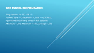
The document details the configuration of a GRE tunnel between two routers (r1 and r2) to enable connectivity between two private networks (192.168.1.0 and 192.168.2.0). It describes various steps including the creation of tunnel interfaces, setting IP addresses, and adding static routes to allow successful pings between devices on each network. Troubleshooting steps are also included to ensure proper communication through the tunnel.


![Gateway of last resort is 20.20.20.2 to network 0.0.0.0
20.0.0.0/30 is subnetted, 1 subnets
C 20.20.20.0 is directly connected, Serial0/0/0
C 192.168.1.0/24 is directly connected, FastEthernet0/0
S* 0.0.0.0/0 [1/0] via 20.20.20.2
R1#
GRE TUNNEL CONFIGURATION](https://image.slidesharecdn.com/ciscoccna-gretunnelconfiguration-160922201306/85/Cisco-CCNA-GRE-Tunnel-Configuration-4-320.jpg)
![GRE TUNNEL CONFIGURATION
Also R2 has a default route to ISP (R3):
R2#show ip route
Codes: C – connected, S – static, I – IGRP, R – RIP, M – mobile, B – BGP
D – EIGRP, EX – EIGRP external, O – OSPF, IA – OSPF inter area
N1 – OSPF NSSA external type 1, N2 – OSPF NSSA external type 2
E1 – OSPF external type 1, E2 – OSPF external type 2, E – EGP
i – IS-IS, L1 – IS-IS level-1, L2 – IS-IS level-2, ia – IS-IS inter area
* – candidate default, U – per-user static route, o – ODR
P – periodic downloaded static route
Gateway of last resort is 30.30.30.1 to network 0.0.0.0
30.0.0.0/30 is subnetted, 1 subnets
C 30.30.30.0 is directly connected, Serial0/0/0
C 192.168.2.0/24 is directly connected, FastEthernet0/0
S* 0.0.0.0/0 [1/0] via 30.30.30.1](https://image.slidesharecdn.com/ciscoccna-gretunnelconfiguration-160922201306/85/Cisco-CCNA-GRE-Tunnel-Configuration-5-320.jpg)


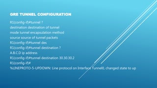


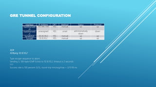
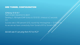

![GRE TUNNEL CONFIGURATION
10.0.0.0/30 is subnetted, 1 subnets
C 10.10.10.0 is directly connected, Tunnel0
20.0.0.0/30 is subnetted, 1 subnets
C 20.20.20.0 is directly connected, Serial0/0/0
C 192.168.1.0/24 is directly connected,
FastEthernet0/0
S* 0.0.0.0/0 [1/0] via 20.20.20.2](https://image.slidesharecdn.com/ciscoccna-gretunnelconfiguration-160922201306/85/Cisco-CCNA-GRE-Tunnel-Configuration-26-320.jpg)


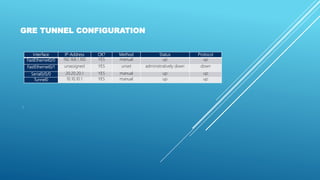
![GRE TUNNEL CONFIGURATION
10.0.0.0/30 is subnetted, 1 subnets
C 10.10.10.0 is directly connected, Tunnel0
20.0.0.0/30 is subnetted, 1 subnets
C 20.20.20.0 is directly connected, Serial0/0/0
C 192.168.1.0/24 is directly connected, FastEthernet0/0
S 192.168.2.0/24 [1/0] via 10.10.10.2
S* 0.0.0.0/0 [1/0] via 20.20.20.2
R1#](https://image.slidesharecdn.com/ciscoccna-gretunnelconfiguration-160922201306/85/Cisco-CCNA-GRE-Tunnel-Configuration-30-320.jpg)