

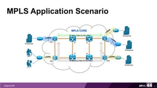

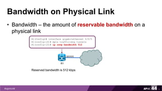
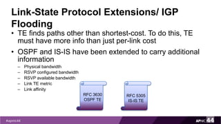

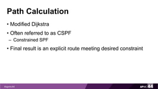
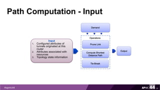
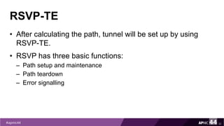

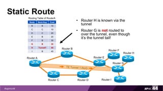
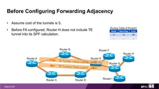

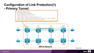
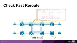
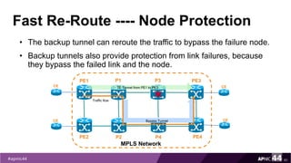
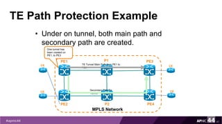
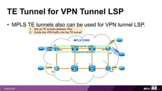
![When the Protected Link is UP
55
PE1
PE2
MPLS Network
PE3
PE4
P1
P2
CE
CE
CE
CE
TE Tunnel from PE1 to PE3
P3
P4
TE0/0/12
TE0/0/12
Router1#traceroute mpls traffic-eng tunnel 100
Tracing MPLS TE Label Switched Path on Tunnel100, timeout is 2
seconds
Type escape sequence to abort.
0 172.16.10.2 MRU 1512 [Labels: 201 Exp: 0]
L 1 172.16.10.1 MRU 1512 [Labels: 521 Exp: 0] 3 ms
L 2 172.16.12.2 MRU 1500 [Labels: implicit-null Exp: 0] 3 ms
! 3 172.16.10.26 3 ms](https://image.slidesharecdn.com/mpls-traffic-engineering-170914232432/85/MPLS-Traffic-Engineering-55-320.jpg)
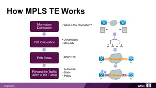
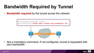
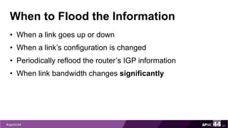
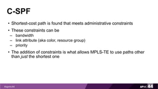
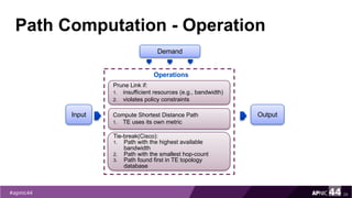
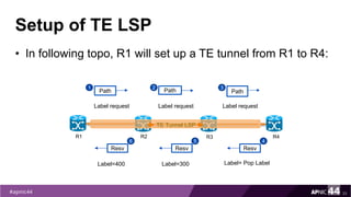
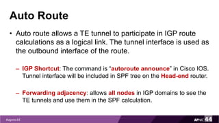
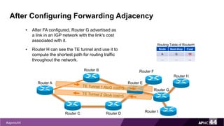
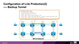
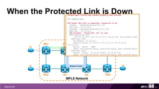
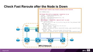
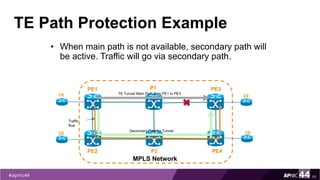
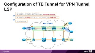
![When the Protected Link is Down
56
PE1
PE2
MPLS Network
PE3
PE4
P1
P2
CE
CE
CE
CE
TE Tunnel from PE1 to PE3
P3
P4
TE0/0/12
TE0/0/12
Router1#traceroute mpls traffic-eng tunnel 100
Tracing MPLS TE Label Switched Path on Tunnel100, timeout is 2
seconds
Type escape sequence to abort.
0 172.16.10.2 MRU 1512 [Labels: 201 Exp: 0]
L 1 172.16.10.1 MRU 1512 [Labels: 1108/521 Exp: 0/0] 4 ms
L 2 172.16.12.13 MRU 1512 [Labels: 816/521 Exp: 0/0] 3 ms
L 3 172.16.12.9 MRU 1512 [Labels: 521 Exp: 0] 3 ms
D 4 172.16.10.26 3 ms
! 5 172.16.10.26 3 ms
Bypass Tunnel](https://image.slidesharecdn.com/mpls-traffic-engineering-170914232432/85/MPLS-Traffic-Engineering-56-320.jpg)
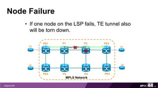
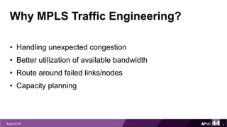
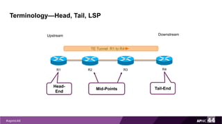
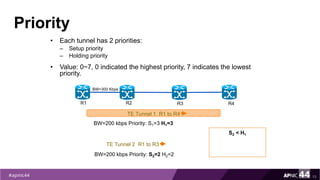
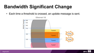
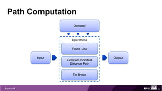
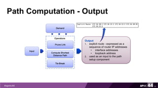
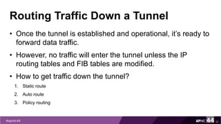
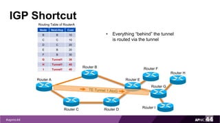
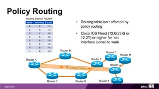
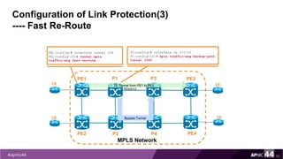
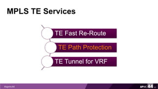
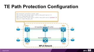
![Primary LSP Before Any Failure
61
PE1
PE2
MPLS Network
PE3
PE4
P1
P2
CE
CE
CE
CE
TE Tunnel from PE1 to PE3
P3
P4
Bypass Tunnel
PE1#traceroute mpls traffic-eng tunnel 100
Tracing MPLS TE Label Switched Path on Tunnel100, timeout is 2
seconds
Type escape sequence to abort.
0 172.16.10.2 MRU 1512 [Labels: 203 Exp: 0]
L 1 172.16.10.1 MRU 1512 [Labels: 522 Exp: 0] 3 ms
L 2 172.16.12.2 MRU 1500 [Labels: implicit-null Exp: 0] 3 ms
! 3 172.16.10.26 3 ms](https://image.slidesharecdn.com/mpls-traffic-engineering-170914232432/85/MPLS-Traffic-Engineering-61-320.jpg)
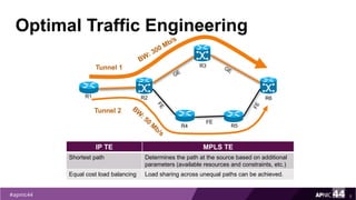
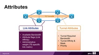
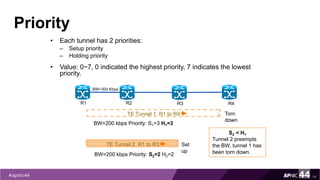
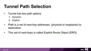
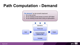
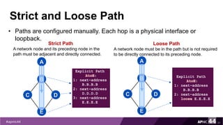
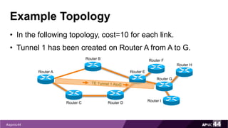
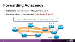
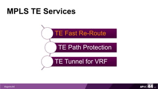
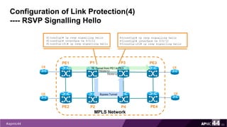
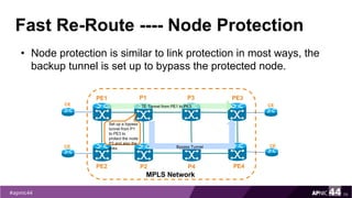
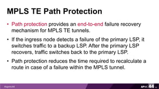
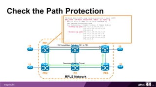
![Bypass LSP Before Any Failure
62
PE1
PE2
MPLS Network
PE3
PE4
P1
P2
CE
CE
CE
CE
TE Tunnel from PE1 to PE3
P3
P4
Bypass Tunnel
P1#traceroute mpls traffic-eng tunnel 1500
Tracing MPLS TE Label Switched Path on Tunnel100, timeout is
2 seconds
Type escape sequence to abort.
0 172.16.12.14 MRU 1512 [Labels: 1113 Exp: 0]
L 1 172.16.12.13 MRU 1512 [Labels: 804 Exp: 0] 4 ms
L 2 172.16.12.9 MRU 1512 [Labels: 616 Exp: 0] 3 ms
L 3 172.16.12.18 MRU 1500 [Labels: implicit-null Exp: 0] 4
ms
! 4 172.16.10.33 4 ms](https://image.slidesharecdn.com/mpls-traffic-engineering-170914232432/85/MPLS-Traffic-Engineering-62-320.jpg)
![Check LSP after the Node is Down
64
PE1
PE2
MPLS Network
PE3
PE4
P1
P2
CE
CE
CE
CE
TE Tunnel from PE1 to PE3
P3
P4
Bypass Tunnel
PE1#traceroute mpls traffic-eng tunnel 100
Tracing MPLS TE Label Switched Path on Tunnel100, timeout is 2
seconds
Type escape sequence to abort.
0 172.16.10.2 MRU 1512 [Labels: 202 Exp: 0]
L 1 172.16.10.1 MRU 1512 [Labels: implicit-null Exp: 0] 4 ms
L 2 172.16.12.13 MRU 1512 [Labels: 804 Exp: 0] 3 ms
L 3 172.16.12.9 MRU 1512 [Labels: 616 Exp: 0] 4 ms
L 4 172.16.12.18 MRU 1500 [Labels: implicit-null Exp: 0] 4 ms
! 5 172.16.10.33 4 ms](https://image.slidesharecdn.com/mpls-traffic-engineering-170914232432/85/MPLS-Traffic-Engineering-64-320.jpg)
![Check LSP before Any Failure
71
PE1
PE2
MPLS Network
PE3
PE4
P1
P2
TE Tunnel Main Path from PE1 to PE3CE
CE
CE
CESecondary Path for Tunnel
PE1#traceroute mpls traffic-eng tunnel 100
Tracing MPLS TE Label Switched Path on Tunnel100, timeout is 2
seconds
......
Type escape sequence to abort.
0 172.16.12.1 MRU 1512 [Labels: 501 Exp: 0]
L 1 172.16.12.2 MRU 1500 [Labels: implicit-null Exp: 0] 5 ms
! 2 172.16.10.26 4 ms](https://image.slidesharecdn.com/mpls-traffic-engineering-170914232432/85/MPLS-Traffic-Engineering-71-320.jpg)
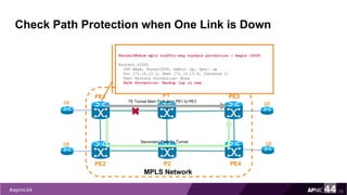
![Check LSP when One Link is Down
72
PE1
PE2
MPLS Network
PE3
PE4
P1
P2
TE Tunnel Main Path from PE1 to PE3CE
CE
CE
CESecondary Path for Tunnel
PE1#traceroute mpls traffic-eng tunnel 100
Tracing MPLS TE Label Switched Path on Tunnel100, timeout is 2
seconds
......
Type escape sequence to abort.
0 172.16.12.14 MRU 1512 [Labels: 1113 Exp: 0]
L 1 172.16.12.13 MRU 1512 [Labels: 811 Exp: 0] 4 ms
L 2 172.16.12.9 MRU 1512 [Labels: 619 Exp: 0] 4 ms
L 3 172.16.12.18 MRU 1500 [Labels: implicit-null Exp: 0] 3 ms
! 4 172.16.10.33 3 ms](https://image.slidesharecdn.com/mpls-traffic-engineering-170914232432/85/MPLS-Traffic-Engineering-72-320.jpg)
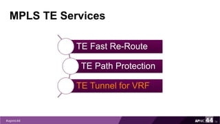
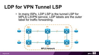
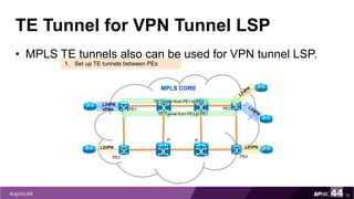


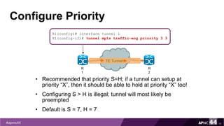
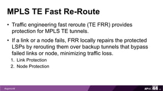
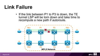
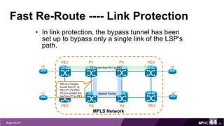
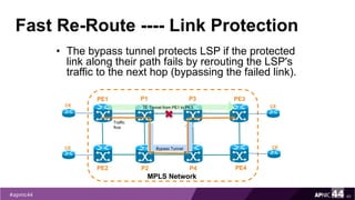
MPLS Traffic Engineering provides mechanisms to optimize network traffic flow and efficiently utilize bandwidth. It determines paths based on additional parameters like available resources and constraints. This allows load balancing across unequal paths and routing around failed links or nodes. MPLS TE uses extensions to IGPs to distribute link attributes and tunnel information. Constrained Shortest Path First (CSPF) is used for path computation to find paths meeting constraints like bandwidth and affinities. Tunnels are set up using RSVP-TE and traffic can be forwarded down tunnels using methods like static routes, auto-routing, or policy routing. Fast Re-Route provides local repair of TE tunnels if a link or node fails to minimize traffic loss.