Configuring GRE Tunnel Through a Cisco ASA Firewall
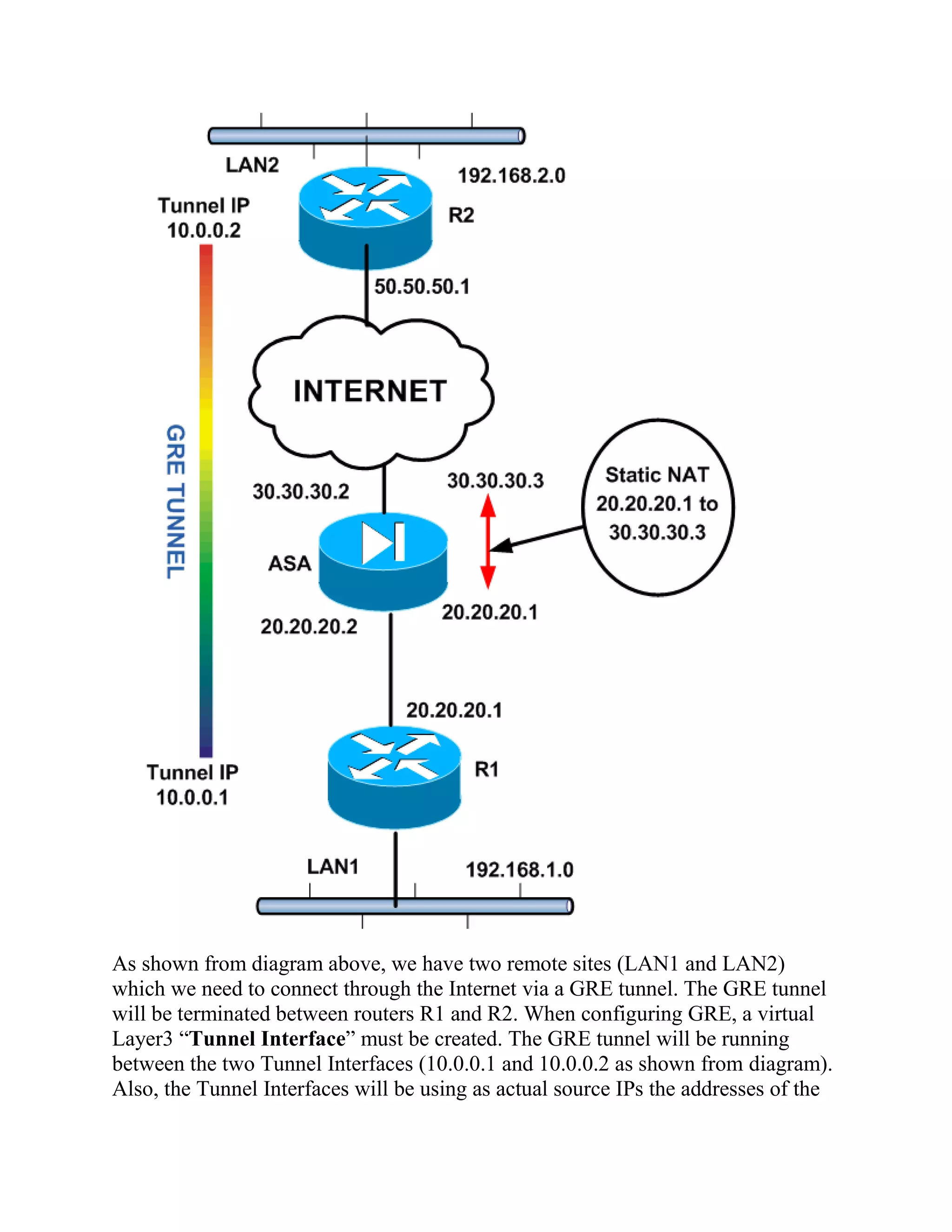
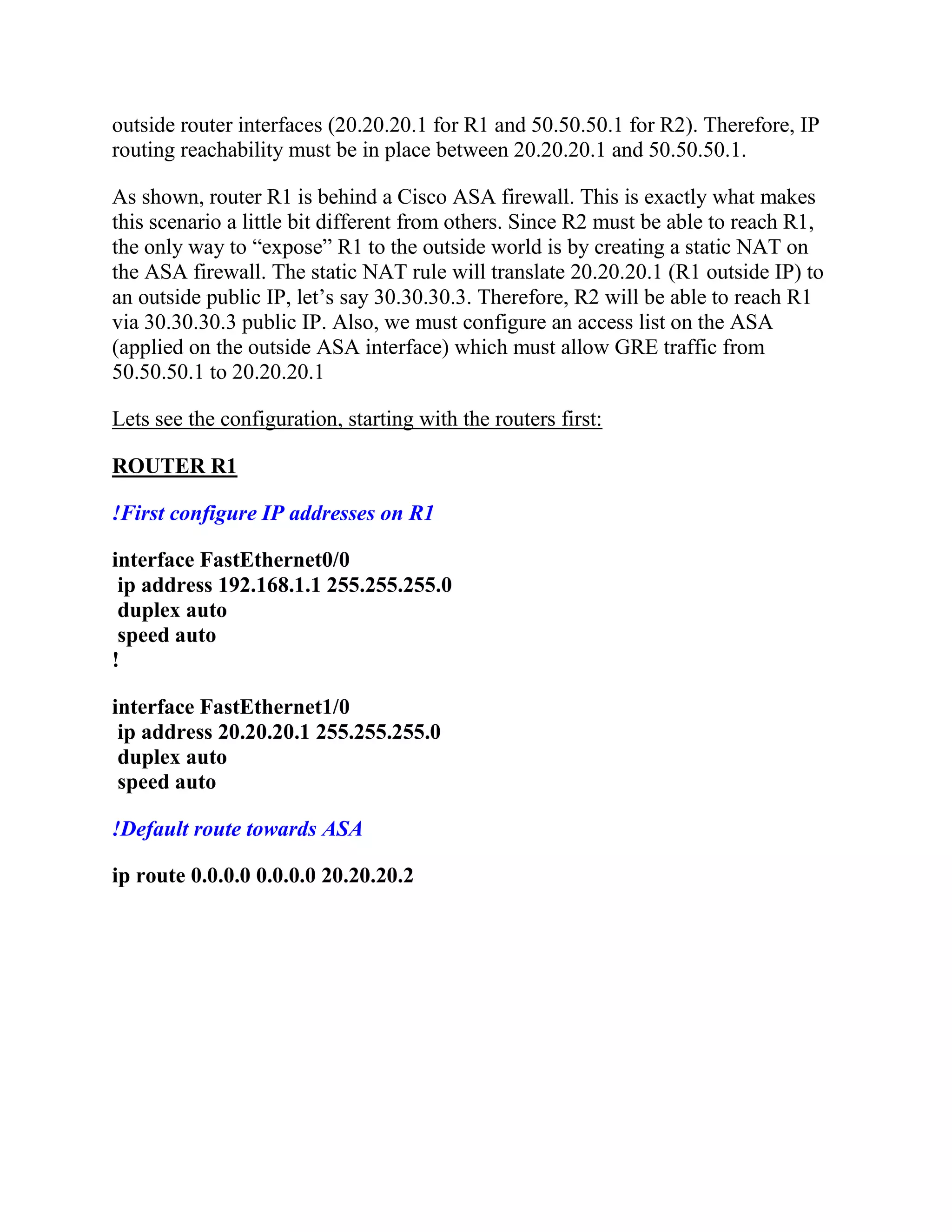
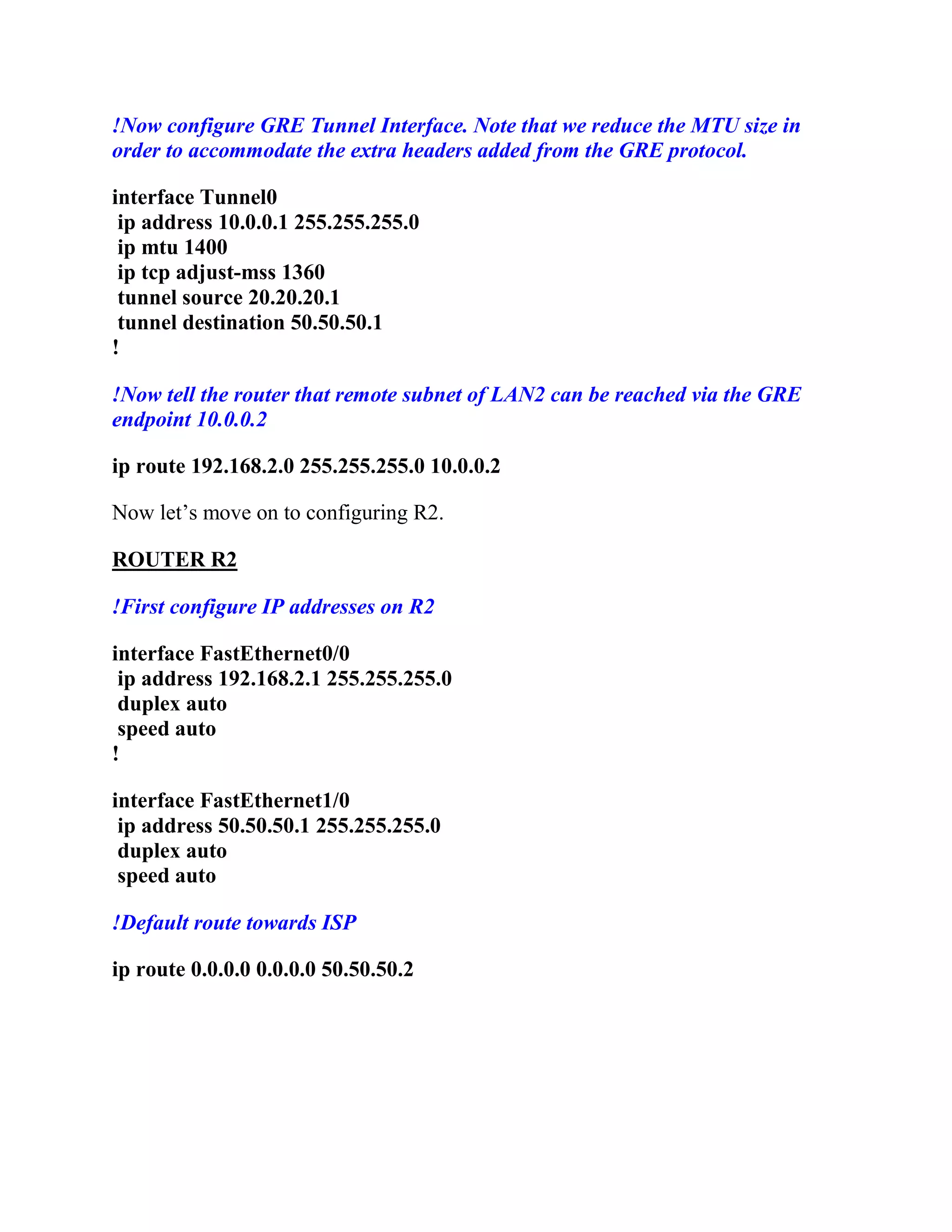
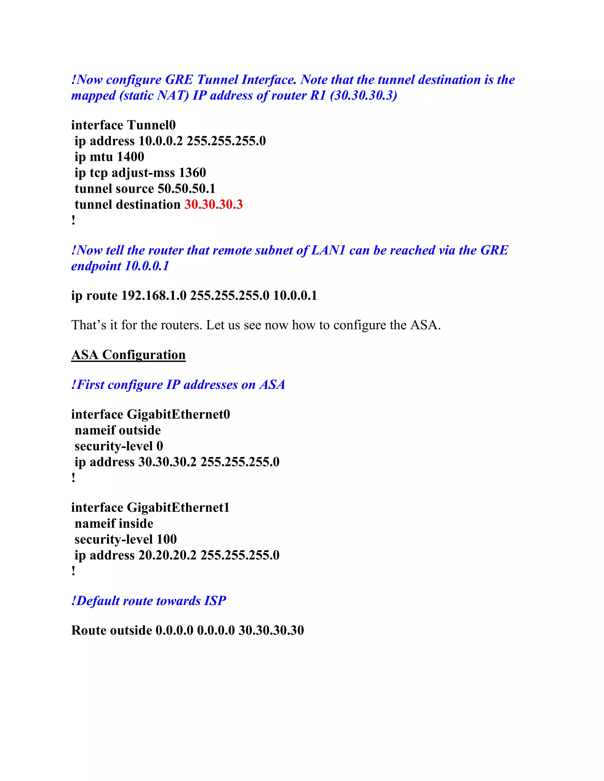
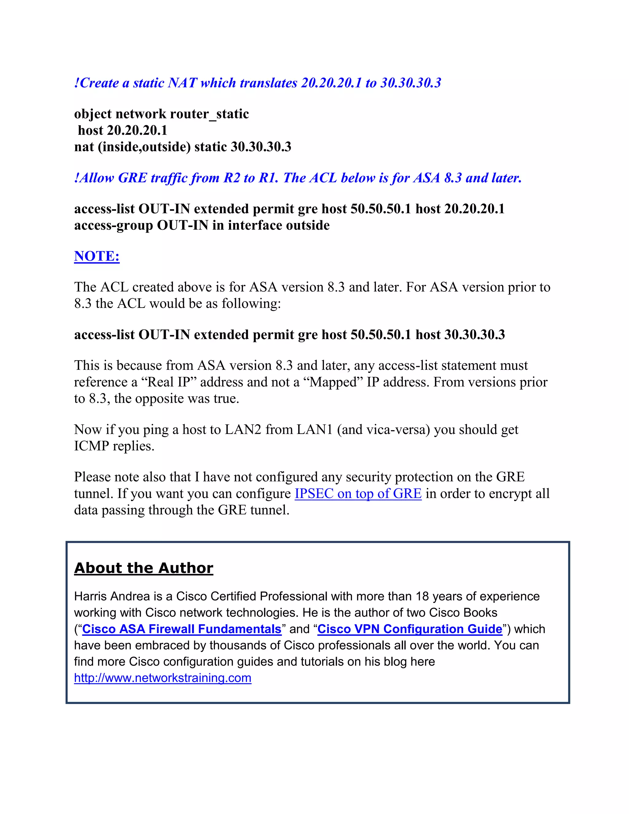
This document provides a tutorial on configuring a GRE tunnel between two Cisco IOS routers, specifically detailing how to pass GRE traffic through a Cisco ASA 5500 firewall. It outlines the necessary configurations for the routers and the ASA, including static NAT and access-list settings, to establish connectivity between two remote LANs. The author emphasizes that GRE tunnels do not encrypt traffic but are useful for transmitting non-unicast traffic, and offers the option of adding IPSec for security.
Configuring GRE Tunnel Through a Cisco ASA Firewall
1.
Configuring GRE TunnelThrough a Cisco
ASA Firewall
In this configuration tutorial I will show you how to configure a GRE tunnel
between two Cisco IOS routers. One of the routers is located behind a Cisco ASA
5500 Firewall, so I will show you also how to pass GRE traffic through a Cisco
ASA as well.
As you might know already, GRE tunnel termination is not supported on Cisco
ASA firewalls. However, this is fully supported on Cisco routers. GRE tunnels are
not secure (no traffic encryption takes place through GRE). However, GRE tunnels
are useful in cases where we need to pass “non-unicast” traffic between two remote
sites (e.g through the Internet). Two scenarios that come to my mind now include
passing routing protocols (such as OSPF) between two remote sites, and also
passing multicast traffic through the GRE tunnel from one site to another.
We will be using the following network diagram:
2.
As shown fromdiagram above, we have two remote sites (LAN1 and LAN2)
which we need to connect through the Internet via a GRE tunnel. The GRE tunnel
will be terminated between routers R1 and R2. When configuring GRE, a virtual
Layer3 “Tunnel Interface” must be created. The GRE tunnel will be running
between the two Tunnel Interfaces (10.0.0.1 and 10.0.0.2 as shown from diagram).
Also, the Tunnel Interfaces will be using as actual source IPs the addresses of the
3.
outside router interfaces(20.20.20.1 for R1 and 50.50.50.1 for R2). Therefore, IP
routing reachability must be in place between 20.20.20.1 and 50.50.50.1.
As shown, router R1 is behind a Cisco ASA firewall. This is exactly what makes
this scenario a little bit different from others. Since R2 must be able to reach R1,
the only way to “expose” R1 to the outside world is by creating a static NAT on
the ASA firewall. The static NAT rule will translate 20.20.20.1 (R1 outside IP) to
an outside public IP, let’s say 30.30.30.3. Therefore, R2 will be able to reach R1
via 30.30.30.3 public IP. Also, we must configure an access list on the ASA
(applied on the outside ASA interface) which must allow GRE traffic from
50.50.50.1 to 20.20.20.1
Lets see the configuration, starting with the routers first:
ROUTER R1
!First configure IP addresses on R1
interface FastEthernet0/0
ip address 192.168.1.1 255.255.255.0
duplex auto
speed auto
!
interface FastEthernet1/0
ip address 20.20.20.1 255.255.255.0
duplex auto
speed auto
!Default route towards ASA
ip route 0.0.0.0 0.0.0.0 20.20.20.2
4.
!Now configure GRETunnel Interface. Note that we reduce the MTU size in
order to accommodate the extra headers added from the GRE protocol.
interface Tunnel0
ip address 10.0.0.1 255.255.255.0
ip mtu 1400
ip tcp adjust-mss 1360
tunnel source 20.20.20.1
tunnel destination 50.50.50.1
!
!Now tell the router that remote subnet of LAN2 can be reached via the GRE
endpoint 10.0.0.2
ip route 192.168.2.0 255.255.255.0 10.0.0.2
Now let’s move on to configuring R2.
ROUTER R2
!First configure IP addresses on R2
interface FastEthernet0/0
ip address 192.168.2.1 255.255.255.0
duplex auto
speed auto
!
interface FastEthernet1/0
ip address 50.50.50.1 255.255.255.0
duplex auto
speed auto
!Default route towards ISP
ip route 0.0.0.0 0.0.0.0 50.50.50.2
5.
!Now configure GRETunnel Interface. Note that the tunnel destination is the
mapped (static NAT) IP address of router R1 (30.30.30.3)
interface Tunnel0
ip address 10.0.0.2 255.255.255.0
ip mtu 1400
ip tcp adjust-mss 1360
tunnel source 50.50.50.1
tunnel destination 30.30.30.3
!
!Now tell the router that remote subnet of LAN1 can be reached via the GRE
endpoint 10.0.0.1
ip route 192.168.1.0 255.255.255.0 10.0.0.1
That’s it for the routers. Let us see now how to configure the ASA.
ASA Configuration
!First configure IP addresses on ASA
interface GigabitEthernet0
nameif outside
security-level 0
ip address 30.30.30.2 255.255.255.0
!
interface GigabitEthernet1
nameif inside
security-level 100
ip address 20.20.20.2 255.255.255.0
!
!Default route towards ISP
Route outside 0.0.0.0 0.0.0.0 30.30.30.30
6.
!Create a staticNAT which translates 20.20.20.1 to 30.30.30.3
object network router_static
host 20.20.20.1
nat (inside,outside) static 30.30.30.3
!Allow GRE traffic from R2 to R1. The ACL below is for ASA 8.3 and later.
access-list OUT-IN extended permit gre host 50.50.50.1 host 20.20.20.1
access-group OUT-IN in interface outside
NOTE:
The ACL created above is for ASA version 8.3 and later. For ASA version prior to
8.3 the ACL would be as following:
access-list OUT-IN extended permit gre host 50.50.50.1 host 30.30.30.3
This is because from ASA version 8.3 and later, any access-list statement must
reference a “Real IP” address and not a “Mapped” IP address. From versions prior
to 8.3, the opposite was true.
Now if you ping a host to LAN2 from LAN1 (and vica-versa) you should get
ICMP replies.
Please note also that I have not configured any security protection on the GRE
tunnel. If you want you can configure IPSEC on top of GRE in order to encrypt all
data passing through the GRE tunnel.
About the Author
Harris Andrea is a Cisco Certified Professional with more than 18 years of experience
working with Cisco network technologies. He is the author of two Cisco Books
(“Cisco ASA Firewall Fundamentals” and “Cisco VPN Configuration Guide”) which
have been embraced by thousands of Cisco professionals all over the world. You can
find more Cisco configuration guides and tutorials on his blog here
http://www.networkstraining.com