Downloaded 498 times
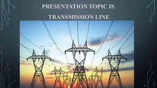
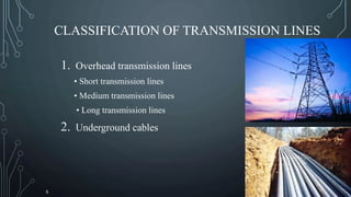
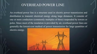
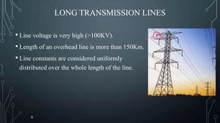
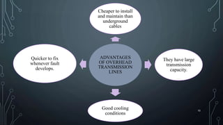
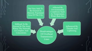
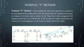
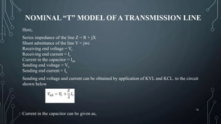
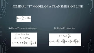
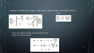
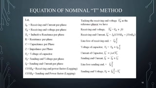
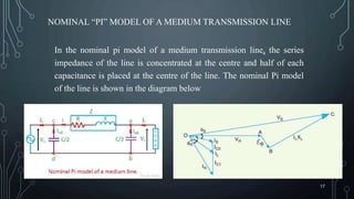
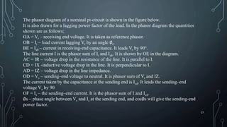
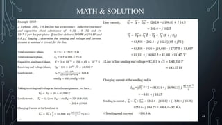
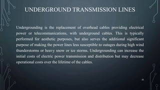
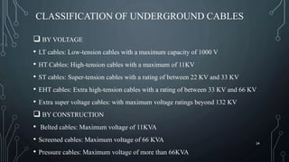


This presentation discusses transmission lines, including overhead power lines and underground cables. It classifies transmission lines as overhead or underground, and further divides them based on voltage and construction. Overhead lines are cheaper but can be affected by the environment, while underground cables are more expensive to install and maintain but are safer and not impacted by the environment. The presentation also covers nominal T and Pi circuit models that can be used to analyze medium transmission lines, and provides equations for calculating voltages and currents at the sending and receiving ends.


